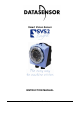
Smart Vision Sensor INSTRUCTION MANUAL www.vision-sensors-illuminators.
DATASENSOR S.p.A. Via Lavino 265 40050 Monte S. Pietro - Bologna - Italy Tel: +39 051 6765611 Fax: +39 051 6759324 http://www.datasensor.com e-mail: info@datasensor.com Datasensor S.p.a. reserves the right to make changes or improvements to products at any time without prior notice. 826003480 Rev.
SVS2 Series Instruction Manual TABLE OF CONTENTS 1. GENERAL INFORMATION ...................................................................................................................1 1.1. Conventions used in the Manual .................................................................................................1 1.2. General description......................................................................................................................1 1.3. Available Models....................
Instruction Manual SVS2 Series 10. INSPECTION SELECTION .................................................................................................................62 10.1. Inspection selection through Graphic User Interface ................................................................62 10.2. Inspection selection through Digital Input..................................................................................63 11. 64 11. INSPECTIONS AND PERIODIC MAINTENANCE.................................
SVS2 Series Instruction Manual 1. GENERAL INFORMATION 1.1. Conventions used in the Manual This manual is intended as a clear, quick-reference guide on SVS2 system operation. If you wish more detailed information on the algorithms and techniques referenced in the manual, the symbol (►) throughout the text refers to Chap.17 that contains a specific TUTORIAL. Boxed text provides definitions to ensure better understanding of the topic under discussion.
Instruction Manual SVS2 Series 2. ELECTRIC CONNECTIONS M12 8-pole: (power supply and I/O) pin 1 : white : pin 2 : brown : pin 3 : green : pin 4 : yellow : pin 5 : gray : pin 6 : pink : pin 7 : blue : pin 8 : red : digital input 1 24 Vdc STROBE for external illuminator output 1 output 2 output 3 GROUND external trigger M12 4-pole Ethernet: (connectivity) pin 1: white/orange: RX+ pin 2: white/green: TX+ pin 3: orange: RXpin 4: green: TX- 3.
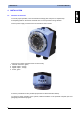
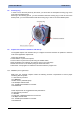
SVS2 Series Instruction Manual 4. INSTALLATION 4.1. Hardware connections To ensure proper operation, never exceed device ratings (see Chap.9 for a complete list). Avoid spilling fluids on the device and make sure it is not exposed to strong vibration. Connect power supply connector and communication cord to sensor. 1. 2. 3. 4. There are four system operation LEDs on sensor body: Network connection, green; Digital output 2, orange; Digital output 1, orange; Power, green.
Instruction Manual SVS2 Series 4.2. Focusing ring In order to focus the area placed by the sensor you should use the transparent focusing ring on the front side of the SVS2 sensor. Referring to the following picture, you must clockwise rotate the focusing ring in order to focus more distant points; you must anticlockwise rotate the focusing ring in order to focus less distant points. 4.3.
SVS2 Series Instruction Manual 4.3.2. Graphic User Interface Installation We recommend closing any programs that are currently running. Insert the supplied CD-ROM into the personal computer drive. After a few seconds, the startup screen is displayed automatically. Note: If the screen does not appear, launch the installation program manually. Select "Run…" from the START menu and type "X:\setup.exe", where "X" is the letter associated with the CD-ROM drive in your system.
Instruction Manual 4.4. SVS2 Series Communicating with the sensor Communication with the sensor occurs via the Ethernet network. Two types of connection are possible: direct connection: personal computer is connected directly to device using a "cross cable". Through LAN: use common network (non-cross) cables normally used to connect devices to routing hubs. This network architecture is termed "star" configuration because all network cables are connected to a central HUB.
SVS2 Series Instruction Manual If you use a direct connection: • From menu START select Control Panel Network Connections LAN Conncetion; • Press the right mouse button and select Properties; • Select Internet Protocol (TCP/IP) then click the Properties button (as shown below); • • Select Use the following IP Address option; Enter the following: IP ADDRESS: 172.27.101.1; SUBNET MASK: 255.255.0.0; Note: no entries for Default Gateway or Use the following DNS Server Address are necessari.
Instruction Manual SVS2 Series 5. SENSOR SETUP 5.1.
SVS2 Series Instruction Manual 5.1.1. Menu bar Lets you load or save the inspection in .XML format on your personal computer and choose Graphic User Interface mode. Files .XML can be used as exchange files to upload the same inspection to several sensors.
Instruction Manual SVS2 Series Sensor : The icons in this menu let you: • establish connection with sensor (Connect to SVS), • access Live mode (Live), • find sensor in the network (Find SVS), • change IP address (Change IP Address), • change inspection (Change Inspection), • finally, update sensor firmware (Firmware Update).
SVS2 Series Instruction Manual 5.1.2. Tool bar Gives quick access to typical functions. It is divided into 4 sections: - The first 3 icons access the same functions contained in the File menu.
Instruction Manual SVS2 Series 5.1.3. Setup bar The Setup bar lets you complete the system configuration procedure in 3 steps. The procedure is described in detail further below; to make it easier, it has been divided into three steps: • Choose inspection mode (step 1); • Set trigger signal, controls and locators (if needed) (step 2); • Set outputs and Test and Run modes (step 3).
SVS2 Series Instruction Manual As you search for and select connected sensors, the control panel displays sensor name, IP address and subnet mask set previously and indicates whether a connection can be created using these settings, so you can enable connection to the desired sensor. Once you have selected the sensor, the control panel lets you set the shooting parameters for the sensor, choose illuminator mode and select your reference image.
Instruction Manual SVS2 Series 5.1.5. Images Buffer It lists the thumbs of images which have been previously acquired and/or downloaded from the personal computer. As the images are loaded, their thumbs appear in the images buffer. The image currently displayed in the work area is highlighted with a red border. You may switch to a different image simply clicking the corresponding thumb or use the tool bar icons to scroll through the buffer, add new images or remove images from the list.
SVS2 Series Instruction Manual 5.1.7. Inspection Explorer Move the mouse pointer to the upper edge of the Help window (pointer changes shape). Hold down the left mouse button and move the pointer up (to enlarge the window) or down (to make window smaller); the Inspection Explorer panel is now displayed. The Inspection Explorer panel shows: • sensor settings; • selected trigger; • operating parameters of illuminators; • control/measurement tools involved in current inspection and their parameter values.
Instruction Manual Click the symbol SVS2 Series to collapse level. 5.1.8. Help The Help Panel provide to the user an intuitive guide through the essential Inspection configuration phases. It is made up by several HTML pages, automatically viewed by the GUI depending on the task performed by the user. It presents a list of typical questions users are likely to ask when they come across certain situations.
SVS2 Series Instruction Manual You may expand all answers by clicking "Show All". Simply click "Hide All" to return to standard view. 5.1.9. Status It provides an instant overview of system status. The bar shows a message on connection status, sensor IP address and the name assigned to the connected sensor. The bar may be expanded by clicking the symbol . The bar shows sensor connection status, current operation and Graphic User Interface version. Click symbol 17 to return to previous display.
Instruction Manual 6. SVS2 Series EASY GRAPHIC USER INTERFACE - INITIAL SETUP Before you can operate the SVS2 system, you will have to perform a preliminary configuration procedure. The "Easy GUI" lets you complete the procedure in three steps. Each step is identified with a number: your progress through the configuration process is visually identified by a red label.
SVS2 Series 6.2. Instruction Manual STEP 1 During this first step, you must decide how you want to go about the inspeection configuration procedure. You may choose to connect to sensor first (On-Line mode) or choose local mode (OffLine mode). Each mode offers different options: Off-Line Mode • New Inspection : Creates a new inspection; • Open Inspection from PC : Loads parameters of an existing inspection saved on PC.
Instruction Manual SVS2 Series 6.2.1. Off-Line Mode The control panel is activated: you need to define the "Reference Image". This may be done by loading an existing image stored previously (button "Load Image"): When you press the "Open" button, the image is displayed in the work area, while its thumbview is shown in the Images Buffer. You may load more than one image and then choose whichever seems best.
SVS2 Series Instruction Manual 6.2.2. On-Line Mode Here you need to select the sensor you wish to connect to. When you select this mode, you will be asked to set connection mode. You may connect to an IP address stored previously or run a new search. When you press the Find SVS button, the system searches for connected sensors in the network and displays their network addresses (IP and Subnet Mask address) and an icon indicates whether they are accessible using this information.
Instruction Manual SVS2 Series When you create a new inspection ("New Inspection") in On-Line mode, this acquisition parameter configuration panel appears: • Stop Live : Stops transfer of video flow to PC Graphic User Interface activated by sensor (Live mode); • Live Status : Indicates when Live mode is active; • Sensor Settings : The result calculated by the exposure meter may not be satisfactory. The image might be too light or too dark.
SVS2 Series Instruction Manual Finally, selecting "Open Inspection from SVS" (available only in On-Line mode) gives access to sensor internal memory: a list of stored inspections is displayed and you may load their parameters to the Graphic User Interface and change them as required at a later time.
Instruction Manual 6.3. SVS2 Series STEP 2 The section of the Setup bar dedicated to step 2 looks like this: Select Trigger Set the type of trigger used to define inspection time instants (for trigger description, see paragraph 8.2). Your selection is added to the Inspection Explorer, in menu level Trigger: "Continuous" trigger is the default trigger: even if you make no selections from the corresponding menu, the system will set up to analyse the image flow continuously.
SVS2 Series 6.4. Instruction Manual STEP 3 In this final step of the configuration process, you may: • set output settings (Set Up Outputs); • start a Test, i.e. run set controls on stored images; • activate Run, i.e. run set controls on the images from the sensor; • turn on monitor mode (Start button), which displays system statistics. Please note that the outputs are disabled in Run mode and images are still processed on the personal computer.
Instruction Manual SVS2 Series Open the pull-down menu to display the different Output Modes. Output is Disabled by default. The other options are: • Toggle: Output toggles between logic values 1 and 0; • Part Pass: Inspection as a whole is considered.
SVS2 Series Instruction Manual 6.4.2. Test In this mode, inspection can be run in two different modalities: • Offline: using previously stored images which must be selected one by one. • Online: sensor is simply used as a camera: acquired images are sent to the PC that processes them using the current inspection controls. It may be used to test the controls included in the inspection. 6.4.3. Run Before you can activate it, one inspection must be stored on the sensor.
Instruction Manual SVS2 Series 7. EASY GRAPHIC USER INTERFACE - EXPERT MODE So far, we have discussed Graphic User Interface operation in the STANDARD mode, which is the default mode when you access the configuration program. If you choose EXPERT mode: in the second inspection setup step, you may set a locator in addition to trigger and control: Select Locator This menu lets you select locators. Your selection is displayed in Inspection Explorer, in menu level "Tools".
SVS2 Series Instruction Manual 8. GRAPHIC USER INTERFACE 8.1. Modes of operation There are two modes of operation available: • On Line with active sensor connection; • Off Line in which you may process images previously stored on the personal computer. The latter mode lets you simulate inspection using previously stored images instead of the video flow sent by the sensor.
Instruction Manual SVS2 Series Image acquisition Processing Pass / Fail INSPECTION This option may be selected from the pull-down menu This type of trigger comes handy, when used in RUN mode, to test inspection parameters: this way, you will see how the controls are run directly on the images acquired by the sensor. 8.3. Controls for the inspection These controls play a key role in the inspection process: they are used to perform controls and measurement on acquired images.
SVS2 Series Instruction Manual The controls use an absolute reference system, with the origin located in the top left corner of the work area. x y 8.4. Locators Normally, the "inspection area" covers the whole work area detected by the camera. The locator lets you reduce the size of the inspection area, for instance to include just an object or a portion of it. Locators are only available in expert mode. Otherwise, inspection area always covers the whole acquired image.
Instruction Manual SVS2 Series 8.4.1. Position Locator Description It is also known as edge locator. Edge: Border of object displayed. This locator identifies the transition between: • a light and a dark area (negative edge) • a dark and light area (positive edge) in the image under examination. For instance, picture a dark object on a light background: object contour is identified as the edge, i.e. the set of dark pixels lying next to light pixels.
SVS2 Series Instruction Manual Parameters After clicking in the work area to create the ROI, the control panel displays the set of parameters that enable control customisation. Please note that different parameters are available in the STANDARD and EXPERT modes: STANDARD mode EXPERT mode • Name : Name assigned to control in Inspection Explorer. Maximum length is 256 characters; • Status : see "Result" further below; • Position Limits : • Min, Max: Minimum and maximum value of detectable position.
Instruction Manual SVS2 Series Example Add a position locator to current inspection. Select "Position" from the pull-down menu: Position the control on the reference image in the work area: the pointer changes shape as soon as it enters the work area. Left-click once at any position to create a default rectangular ROI. At the same time, the control features and the result of its application to the reference image appear in the control panel. Set ROI size and position as required, as explained above.
SVS2 Series Instruction Manual 8.4.2. Pattern Match Locator Description In pattern match operation, sample object and target object are compared to determine if they are similar. (Pattern match ►) The locator searches for the sample through 360° inside the inspection area and determines its position. In this way it is possible to detect the horizontal translations and either the vertical displacement of the object among the inspection area.
Instruction Manual SVS2 Series After clicking in the work area to create the ROI, the control panel displays the set of parameters that enable control customisation. STANDARD mode • Name : Name assigned to control in Inspection Explorer. Maximum length is 256 characters; • Status : see "Result" further below; • Match score : o Expected : Threshold used for inspection result evaluation.
SVS2 Series Instruction Manual Example Add a Pattern Match locator to current inspection. Select "Pattern Match" from the pull-down menu: Position the control on the reference image in the work area: the pointer changes shape as soon as it enters the work area. Left-click once at any position to create a default rectangular ROI. At the same time, the control features and the result of its application to the reference image appear in the control panel.
Instruction Manual 8.5. SVS2 Series Controls The controls are tools used to set inspection specifications. The SVS2 system offers a broad range of controls: Name Brightness Contrast Contour Match Edge Count Width Pattern Match Position Geometric Pattern Match Available in OR version Available in AOR version This way, the system can be adapted to meet specific inspection requirements.
SVS2 Series Instruction Manual It is possible to set more complex inspection processes, with acquired images processed in parallel undergoing simple or complex measurements/controls at the same time, with the results connected to different outputs: Acquired Image Control / Measurement No. 1 Output no. 1 Pass / Fail Control / Measurement No. 2 Output no. 2 Pass / Fail Control / Measurement No. 3 Output no.
Instruction Manual SVS2 Series 8.5.1. Brightness Description The term brightness signifies the "brightness" attribute of an image. Once the ROI has been set, the control calculates mean pixel brightness inside the ROI. Selection Pointer shape Positioning Click any point inside the work area to create a rectangular ROI with a small white square at the bottom right corner.
SVS2 Series Instruction Manual Parameters After clicking in the work area to create the ROI, the control panel displays the set of parameters that enable control customisation. Please note that different parameters are available in the STANDARD and EXPERT modes: • Name : Name assigned to control in Inspection Explorer. Maximum length is 256 characters; • Status : see "Result" further below; • Brightness score: o Expected : Threshold used for inspection result evaluation.
Instruction Manual SVS2 Series Example Add "Brightness" control with rectangular ROI to current inspection. Select "Brightness" from the pull-down menu: Position the control on the reference image in the work area: the pointer changes shape as soon as it enters the work area. Left-click once at any position to create a default rectangular ROI. At the same time, the control features and the result of its application to the reference image appear in the control panel.
SVS2 Series Instruction Manual 8.5.2. Contrast Description The term contrast signifies the ratio of lightest to darkest pixel brightness in an image. When contrast is too sharp, an image will mostly be made up of white and black areas, whereas weak contrast will turn out a greyish image. Selection Pointer shape Positioning Click any point inside the work area to create a rectangular ROI with a small white square at the bottom right corner.
Instruction Manual SVS2 Series Parameters After clicking in the work area to create the ROI, the control panel displays the set of parameters that enable control customisation. Please note that the same parameters are available in the STANDARD and EXPERT modes: • Name : Name assigned to control in Inspection Explorer. Maximum length is 256 characters; • Status : see "Result" further below; • Contrast score : o Expected : Threshold used for inspection result evaluation.
SVS2 Series Instruction Manual Example Add "Contrast" control with rectangular ROI to current inspection. Select "Contrast" from the pull-down menu: Position the control on the reference image in the work area: the pointer changes shape as soon as it enters the work area. Left-click once at any position to create a default rectangular ROI. At the same time, the control features and the result of its application to the reference image appear in the control panel.
Instruction Manual SVS2 Series 8.5.3. Contour Match Description The contour match operation consists in comparing the contour of a sample object with that of a target object to determine their similarity. (Contour match ►) After an initial setup stage designed to set the master contour on the reference image, it’s very important that the ROI contains a closed shape entirely. Then, the system will search for this contour through 360° in target images as they are acquired.
SVS2 Series Instruction Manual Parameters After clicking in the work area to create the ROI, the control panel displays the set of parameters that enable control customisation. Please note that different parameters are available in the STANDARD and EXPERT modes: • Name : Name assigned to control in Inspection Explorer.
Instruction Manual SVS2 Series Example Add "Contour Match" control to current inspection to detect the contour of a bright object on a dark background. Select "Contour Match" from the pull-down menu: Position the control on the reference image in the work area: the pointer changes shape as soon as it enters the work area. Left-click once at any position to create a default rectangular ROI.
SVS2 Series Instruction Manual 8.5.4. Edge Count Description This control identifies all edges (edge detection ►) located inside the ROI. Based on the first derivative of the pixel brightness variation function, the maximum positive peak is identified if control is targeting a positive edge, or the maximum negative peak is identified when targeting a negative edge.
Instruction Manual SVS2 Series Please note that different parameters are available in the STANDARD and EXPERT modes: STANDARD mode EXPERT mode • Name : Name assigned to control in Inspection Explorer. Maximum length is 256 characters; • Status : see "Result" further below; • Counts limits : Lets you specify the minimum and maximum number of edges that can be detected; o Min, Max: These parameters let you specify the minimum and maximum number of edges that can be detected.
SVS2 Series Instruction Manual Example Add an "Edge count" control to current inspection to identify up to two edges. Select "Edge Count" from the pull-down menu: Position the control on the reference image in the work area: the pointer changes shape as soon as it enters the work area. Left-click once at any position to create a default rectangular ROI. At the same time, the control features and the result of its application to the reference image appear in the control panel.
Instruction Manual SVS2 Series 8.5.5. Width Description This control is also termed "gauge" and lets you measure the distance between two points. It uses the edge detection technique to identify object edges and then calculates the distance between the edges. Selection Pointer shape Positioning Click any point inside the work area to create a rectangular ROI with a small white square at the bottom right corner. To change ROI size, left-click and drag the square.
SVS2 Series Instruction Manual STANDARD mode EXPERT mode • Name : Name assigned to control in Inspection Explorer. Maximum length is 256 characters; • Status : see "Result" further below; • Width limits : o Min, Max: These parameters let you specify the minimum and maximum width value that can be detected. These thresholds must be compatible with the value found (shown in the "Calculated" bar).
Instruction Manual SVS2 Series Example Add a "Width" edge to current inspection using the Graphic User Standard in STANDARD mode. Select "Width" from the pull-down menu: Position the control on the reference image in the work area: the pointer changes shape as soon as it enters the work area. Left-click once at any position to create a default rectangular ROI. At the same time, the control features and the result of its application to the reference image appear in the control panel.
SVS2 Series Instruction Manual 8.5.6. Pattern Match Description The term pattern match signifies a process that searches for a pattern similar to the master image inside the target image using its brightness matrix. (Pattern match ►) Once the ROI has been set, the control calculates the edge points (features) that show significant differences in pixel brightness. All features are displayed in the form of small yellow squares.
Instruction Manual SVS2 Series Parameters After clicking in the work area to create the ROI, the control panel displays the set of parameters that enable control customisation. STANDARD mode EXPERT mode • Name : Name assigned to control in Inspection Explorer. Maximum length is 256 characters; • Status : see "Result" further below; • Match score : o Expected : Threshold used for inspection result evaluation.
SVS2 Series Instruction Manual Example Add a "Pattern Match" control to current inspection. Select "Pattern Match" from the pull-down menu: Position the control on the reference image in the work area: the pointer changes shape as soon as it enters the work area. Left-click once at any position to create two default rectangular ROIs. At the same time, the control features and the result of its application to the reference image appear in the control panel.
Instruction Manual SVS2 Series 8.5.7. Position Description This control identifies the object position edge (edge detection ►) located inside the ROI. Based on the first derivative of the pixel brightness variation function, the maximum positive peak is identified if control is targeting a positive edge, or the maximum negative peak is identified when targeting a negative edge.
SVS2 Series Instruction Manual Please note that different parameters are available in the STANDARD and EXPERT modes: STANDARD mode EXPERT mode • Name : Name assigned to control in Inspection Explorer. Maximum length is 256 characters; • Status : see "Result" further below; • Position Limits : o Min, Max: Minimum and maximum value of detectable position. These thresholds must be compatible with the value found (shown in the "Calculated" bar).
Instruction Manual SVS2 Series Add a "Position" control to current inspection to identify up to two edges. Select "Position" from the pull-down menu: Position the control on the reference image in the work area: the pointer changes shape as soon as it enters the work area. Left-click once at any position to create a default rectangular ROI. At the same time, the control features and the result of its application to the reference image appear in the control panel.
SVS2 Series 9. Instruction Manual TEACH BUTTON On the top of the sensor body there is a very important button with many functionalities. In the section Output Setup->Teach Button in the Graphic User Interface it is possible to enable its functions. However, the Teach Button functions are available only when the sensor is not connected with the GUI.
Instruction Manual SVS2 Series 10. INSPECTION SELECTION In order to change the current Inspection running on SVS you can choose between two options, described in the following paragraphs: inspection selection through Graphic User Interface and inspection selection through digital input. 10.1.
SVS2 Series Instruction Manual 10.2. Inspection selection through Digital Input To select the current inspection running on SVS a digital input with a special protocol is used. The protocol is composed of a prologue followed by an epilogue. Basically the prologue is composed of 3 pulses with a width of 10-100 ms and a duty cycle of 50 % .
Instruction Manual SVS2 Series The following SVS Settings dialog window will appear: In the bottom view on the dialog window the Digital I/O pulses configuration group box shows a numeric up-down control that can be used to change the current digital Input pulses width: values between 10 ms and 100 ms will be accepted from the SVS sensor. Once you are confident your configuration is completed, press the Ok button to save the configuration on the sensor. If you press Close button, nothing will change.
SVS2 Series Instruction Manual 11. INSPECTIONS AND PERIODIC MAINTENANCE Correct system maintenance consists in removing dust or foreign objects from sensor and keeping the configuration software updated to the latest release. Remove any dust build-up from sensor body using a soft cloth; if needed, dampen cloth slightly with a mild detergent solution. To clean off dust and fingerprints from the lenses, use an anti-static compressed air can. Use a cloth and a specific lens detergent to remove any residue.
Instruction Manual SVS2 Series 12.
SVS2 Series Instruction Manual 13. LIST OF AVAILABLE MODELS MODEL SVS2-06-DE-OBJ 6mm, ETHERNET CONN., OBJ SVS2-08-DE-OBJ 8mm, ETHERNET CONN., OBJ SVS2-12-DE-OBJ 12mm, ETHERNET CONN., OBJ 14.
Instruction Manual SVS2 Series 15.
SVS2 Series Instruction Manual MODELLO SVS-ST-5068 SVS-ST-5066 DESCRIZIONE U-shaped fixing bracket for angle adjustment L-shaped fixing bracket for 90° mounting N° ORDINE 95A901320 95A901330 SVS-CV-RJ45C-03 3 m crossed Ethernet cable 95A901340 SVS-CV-RJ45D-03 SVS-MK-01 3 m direct Ethernet cable Mounting Kit 95A901350 95A901380 MODEL SVS-ST-5068 DESCRIPTION L-shaped fixing bracket for 90° mounting 95A901320 SVS-ST-5066 U-shaped fixing bracket for angle adjustment 95A901330 SVS-CV-RJ45C-03 SV
Instruction Manual SVS2 Series 16. TUTORIAL 16.1. ► Digital image Digitization allows real images acquired by a camera to be treated using a processor. This is done in two steps: o sampling: image is divided into a dot matrix; dots are termed picture elements (or more commonly pixels); o quantization: each pixel is associated to a numeric value. Such information may signify point brightness for gray scale images (0 = black, 255 = white), or three values (Red-Blue-Green, RGB coding) for colour images.
SVS2 Series Instruction Manual 16.2. ► Machine vision This is a specific branch of Computer Vision (or "artificial vision"). Computer vision is a generic concept which applies to all processes aimed at extracting information from images. On the other hand, machine vision has a specific purpose, i.e. control the operation of equipment and machinery in industrial applications (such as manufacturing lines or goods handling applications).
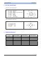
Instruction Manual SVS2 Series 16.4. ► Lighting Options Ring light A technique with many application possibilities. The illuminator is mounted directly on the sensor and illuminates any object in front of it. A ring light provides diffused lighting over a small area. - Advantages: provides correct lighting also for small objects. Reduces shadows on images with protrusions. Centres the light on the image.
SVS2 Series Instruction Manual 16.5. ► Blob / Blob analysis A blob (blob stands for Binary Large Object) is a set of adjacent pixels having the same brightness. Typically, they are searched and identified in binarized images (►), in an attempt to group all bright pixels and all dark pixels together into connected structures.
Instruction Manual SVS2 Series 16.6. ► Binarization This is a process that converts any given image to a two-level image (in our instance, black and white). Conversion is based on a threshold that classifies the individual pixels as "level 255" (or "white") or "level 0" (or "black") depending on whether they are above or below set threshold. Let us consider a shot of a dark object on a bright background.
SVS2 Series Instruction Manual 16.7. ► Edge / Edge Detection The term "edge" signifies the contour of the object shown in an image. From an operational viewpoint, what happens is that the system detects the difference in the brightness of adjacent pixels compared to a certain threshold value.
Instruction Manual SVS2 Series 16.8. ► Inspection times Total inspection duration depends on three factors: • exposure time (►); • acquisition time; • processing time Exposure time: Time period during which the acquisition device is exposed to light. The longer the exposure time, the greater the quantity of light entering the device.
SVS2 Series Instruction Manual 16.10. ► Pattern match In the pattern match method, a sample object is recognised by searching for the matching brightness matrix in the target image. The system stores a "pattern" of the master image and tries to find that pattern in all inspected target images. During the search process, the pattern is made to slide over the image while brightness differences are calculated pixel by pixel.
Instruction Manual SVS2 Series 17. GLOSSARY • Algorithm : set of instructions that accomplish a task in a finite number of steps; • CMOS : Image acquisition device. It consists of a set of photo-sensitive elements ( pixels) arranged in a matrix that are exposed to light through a glass window on chip surface; • Cross cable : special network cable where the transmit wires and the receive wires are crossed.