FS9Z-B1073 FS1A SERIES Safety Controller SafetyOne User’s manual
SAFETY PRECAUTIONS z Carefully read this user’s manual to ensure correct operation before starting installation, wiring, operation, maintenance, and inspection of the SafetyOne. z In this user’s manual, safety precautions are categorized in order of importance- Warning and Caution, as follows: Warning Warning notices are used to emphasize that improper operation may cause severe personal injury or death.
Warning z Calculate respective safety distances, taking into consideration the response time of the SafetyOne, safety devices to be connected to the SafetyOne, and each other device that forms a part of the system configuration. z Applicable safety performance is dependent on each system configuration.
Warning z Do not connect devices having input and output specifications that do not satisfy the requirements of the SafetyOne. Refer to the following for information on the requirements of connected devices.
Caution z SafetyOne is designed for installation within an enclosure. Do not install SafetyOne outside an enclosure. Install SafetyOne in enclosure rated IP54 or higher. z Install SafetyOne in environments described in the catalog, instruction sheet, and user’s manual. If SafetyOne is used in places where the SafetyOne is subjected to high temperature, high humidity, condensation, corrosive gases, excessive vibrations, and excessive shocks then electrical shocks, fire hazard, or malfunction may result.
BEFORE GETTING STARTED Thank you for your purchase of the IDEC SafetyOne (Type Number FS1A-C01S). This user’s manual describes the specifications, and the procedures for installing and operating the SafetyOne. Read this manual carefully before using the SafetyOne so that you have an adequate understanding of its functions and performance. About directives and standards SafetyOne is approved for following directives and standards by TÜV SÜD. 1.
CONTENTS Chapter1 OVERVIEW .......................................................................................................................................................... 1-1 About the SafetyOne .............................................................................................................................................. 1-1 Features of the SafetyOne ....................................................................................................................................
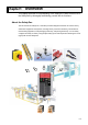
Chapter1 OVERVIEW This chapter provides an understanding of the SafetyOne. Make efficient use of the SafetyOne by thoroughly familiarizing yourself with its functions. About the SafetyOne The FS1A series of SafetyOneTM controllers provides safeguard measures for various factory automation equipment and systems, including robots, production machinery, semiconductor manufacturing apparatus, food packaging machinery, and printing machinery.
Features of the SafetyOne z You can configure safety circuits without the use of complicated external wiring or special software, thereby greatly reducing the number of development man-hours required for product certification and the training time of safety responsible persons. z You can use the DIP switches to select from eight different types of logic circuits and set the OFF-delay timer value to best match your application.
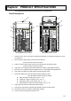
Chapter2 PRODUCT SPECIFICATIONS This chapter describes product specifications of the SafetyOne. Parts Descriptions ⑪ ① ⑩ ENTER LOGIC No. 1 2 3 4 5 6 7 8 ⑧ ⑤ TIMER(S) ⑨ 0 .1 .5 1 2 5 15 30 ⑥ 0 LOGIC ERROR .1 .5 1 ④ ② IN T0 IN X0 T1 X1 T2 X2 T3 X3 T4 2 5 15 30 TIMER (S) SAFE-IN X0 X1 X2 X3 Y0 Y1 X4 X5 Y2 Y3 X6 X7 X1 0 X1 1 X1 2 X1 3 X1 4 X1 5 SAFE-OU T ⑦ SOLENOID -OUTT -OU Y1 7 Y20 X1 7 .
Dimensions 122.0 114.5 72.0 109.5 113.5 1.7 1.5 12 0°0 ' 133.
General specifications Operating conditions Operating temperature (Surrounding air temperature) -10 to +55℃ (no freezing) Relative operating humidity 10 to 95% (non-condensing) Storage temperature -40 to +70℃ (no freezing) Relative storage humidity 10 to 95% (non-condensing) Pollution degree 2(IEC/EN 60664-1) Degree of protection IP20(IEC/EN 60529) Corrosion immunity Atmosphere be free from corrosive gas Altitude Vibration resistance Shock resistance Connector durability Operation strength o
Note1. Time to shut OFF safety outputs after safety inputs are turned OFF or input monitor error is detected (in case of OFF-delay timer is 0s). If the timer value except 0s, add the selected OFF-delay time to this reaction time. Note2. Time to shut OFF safety outputs after error (except input monitor error) is detected, or configuration change is detected. This reaction time does not depend on OFF-delay timer value. Note3.
Applicable standards Standard IEC 61508 Part1-7 EN 954-1 ISO 13849-1 IEC/EN 62061 IEC/EN 61496-1 IEC/EN 60204-1 IEC/EN 61131-2 Title Functional safety of electrical/electronic/programmable electronic safety-related systems Safety of Machinery -- Safety-related Parts of Control Systems -- Part 1: General Design Principles Safety of machinery -- Safety-related parts of control systems -- Part 1: General principles for design Safety of machinery - Functional safety of safety-related electrical, electronic and
Safety performance SafetyOne can be used in a system for control category B to 4. Average probability of failure on demand (PFD) and Probability of a dangerous failure per hour(PFH) The following table describes PFD and PFH. They are needed for calculation of safety integrity level (SIL) which is applied to a system with SafetyOne. SafetyOne can be used in a system for SIL 1 to 3. 6 months Average Probability of Failure on Demand (PFD) < 1.8 x 10⁻⁵ 1 year < 3.
Safety input specifications Drive terminal specifications (T0, T1, T2, T3, T4, T5, T6, T7, T10, T11, T12, T13, T14, T15) Rated drive voltage Power supply voltage Minimum drive voltage Power supply voltage – 2.0V Number of drive terminals 14 Maximum drive current 20mA per port (at 28.8V DC) Note1 Receive terminal specifications (X0, X1, X2, X3, X4, X5, X6, X7, X10, X11, X12, X13, X14, X15) Rated input voltage 24V DC Input ON voltage 15.0V DC to 28.8V DC Input OFF voltage Open or 0V DC to 5.
Start input specifications Rated input voltage 24V DC Input ON voltage 15.0V DC to 28.8V DC Input OFF voltage Number of start input terminals Input current Open or 0V DC to 5.0V DC 2 (X16,17) 5mA per port (at rated voltage) Type of input Sink type input (for PNP output), Type 1 (IEC/EN61131-2) Cable length Note1 100m maximum (total wiring length per 1 input) Allowable wiring resistance 300Ω maximum Note1.
Safety output specifications Output type Source output (N channel MOSFET) Rated output voltage Power supply voltage Minimum voltage Number of output terminals Point Maximum output current total Power supply voltage - 2.0V 4(Y0, Y1, Y2, Y3) 500mA maximum Leakage current 0.1mA maximum Allowable inductive Load 1A maximum Note1 L/R=25ms Allowable capacitive load Cable length 1uF maximum Note2 100m maximum (total wiring length per 1 output) Note1.
Monitor output specifications Output type Source output (N channel MOSFET) Rated output voltage Power supply voltage Minimum output voltage Number of outputs Point Power supply voltage - 2.0V 11(Y4, Y5, Y6, Y7, Y10, Y11, Y12, Y13, Y14, Y15, Y16) 20mA maximum total 220mA maximum Maximum output current Leakage current Cable length 0.1mA maximum Note1 100m maximum (total wiring length per 1output) Note1.
Solenoid/Lamp output specifications Output type Source output (N channel MOSFET) Rated output voltage Power supply voltage Minimum output voltage Number of outputs point Power supply voltage - 2.0V 2 (Y17, Y20) 500mA maximum total 500mA maximum Maximum output current Leakage current Allowable Inductive Load Cable length 0.1mA maximum Note1 L/R=25ms Note2 100m maximum (total wiring length per 1 output) Note1.
Indicators (1) (2) (3) 0 .1 .5 1 2 5 15 30 LOGIC ERROR SAFE-IN (4) X0 X1 X2 X3 X4 X5 X6 X7 TIMER(S) SAFE-OUT Y0 Y1 Y2 Y3 (1) Logic LED (green) (2) Error LED (red) (3) Timer LED (green) (4) Input/Output status LED (orange) -SAFE-IN SOLENOID X10 X11 -OUT -START-IN X12 X13 X14 X15 -SOLENOID-OUT Y17 Y20 START-IN X16 -SAFE-OUT X17 (1) Logic LED Indication “1”... “8” Status ON Blink Descriptions The selected logic is in Run or Protection state.
(3) Timer LED Indication Status Descriptions 0 ON No OFF-delay (safety outputs shut off immediately) .1 ON OFF-delay timer 0.1s .5 ON OFF-delay timer 0.
Specification of configuration switches (3) ENTER LOGIC No. TIMER(S) (1) Logic switch 1 2 3 4 5 6 7 8 0 .1 .5 1 2 5 15 30 (2) Timer switch (1) (2) (3) Enter button (1) Logic switch The logic switch is an 8-digit DIP switch for use in logic configuration. When one of 8 digits is selected, the corresponding logic in the SafetyOne is activated. See “Chapter 5 Logic” for further information of each logic. The upper position of each digit is the ON state. Multiple switches must not be selected.
Connector specifications ■Input connector T0 X0 T1 X1 T2 X2 T3 X3 T4 X4 T5 X5 T6 X6 T7 X7 T100 T1 X100 X1 T111 T1 X111 X1 T122 T1 X122 X1 T133 T1 X133 X1 T144 T1 X144 X1 T155 T1 X155 X1 X166 X1 X177 X1 Connector type: - Spring clamp connector (30 poles) FS9Z-CN01 [IDEC] (Tyco Electronics AMP type Number: 2-1871940-5) - Crimp connector (30 poles)Note1 (Tyco Electronics AMP type Number: 2-1871946-5) Terminal Terminal Terminal Terminal name No. name No.
■Output connector Y0 Y1 Y2 Y3 Y4 Y5 Y6 Y7 Y100 Y1 Y111 Y1 Y122 Y1 Y133 Y1 Y144 Y1 Y155 Y1 Y166 Y1 Y177 Y1 Y20 N.C V+ V- FE FE Connector type: - Spring Clamp connector (22 poles) FS9Z-CN02 [IDEC] (Tyco Electronics AMP type No.:2-1871940-1) - Crimp connector (22 poles) (Tyco Electronics AMP type No.: 2-1871946-1) Terminal Terminal Terminal Terminal name No. name No.
Chapter3 INSTALLATION AND WIRING This chapter describes methods and precautions for installing and wiring the SafetyOne. Before starting installation and wiring, be sure to read “SAFETY PRECAUTIONS” in the beginning of this manual and understand the precautions described under WARNING and CAUTION. Warning ● Turn off power to SafetyOne before starting installation, removing, wiring, maintenance, or inspection of SafetyOne. Failure to turn power off may cause electrical shocks or fire hazard.
● Prevent SafetyOne from falling while moving or transporting the SafetyOne, otherwise damage or malfunction of the SafetyOne may result. ● Prevent metal fragments and pieces of wire from dropping inside the SafetyOne housing. ● Install SafetyOne, so that there is adequate spacing from walls, heat generating bodies, and peripherals, taking into consideration space requirements for maintenance and ventilation.
Installation method ■ Installation location and direction When the SafetyOne is installed in an enclosure, confirm that installation environments meet the product specifications. Using in environments such as a described below, (over the product specifications) may cause fire hazard, damage, or malfunction. ・SafetyOne should not be exposed to excessive dust, dirt, salt, vibration or shocks. ・Do not use SafetyOne in an area where corrosive chemicals or flammable gases are present.
Mount SafetyOne on a vertical plane as shown in Fig.3.2. All other installation directions are not allowed. BNL6 mounting clip Fig. 3.2 Correct installation direction Upwards Sideways Downwards Fig. 3.
■ Installing on DIN Rails Mount and remove SafetyOne on 35mm-wide DIN rails according to the following instructions. Applicable DIN rail: (for example) BAA1000 (IDEC) Mounting on DIN rail 1. Fasten DIN rail to a panel using screws. 2. With the top of SafetyOne unit facing up, as shown in Fig. 3.4, insert the groove, on the rear of the unit, and press the unit in the direction of the arrow. 3. Use BNL6 mounting clips (sold separately) on both sides of SafetyOne to prevent it from moving sideways.
Wiring method SafetyOne has to two kinds of connectors = spring clamp = (optional) and crimp.Note1 Note1. For detailed information of Crimp connector, consult Tyco Electronics AMP. ●Applicable connectors and mounting to SafetyOne Applicable connectors Type No. of pole Part No.
● Wiring for spring connector Do not wire the connector while it is connected to the SafetyOne, as this can damage the connector and the SafetyOne. To connect the wire, use a connecting tool (FS9Z-SD01 [IDEC] (Tyco Electronics AMP Type Number: 0-2040798-1) or a commercially-available screwdriver. It is recommended that you use a dedicated connecting tool to prevent any scratches or damage to the connector housing and spring. When rewiring, use wire with same gauge. ● Wiring with a connecting tool 1.
3-8
Chapter4 BASIC OPERATIONS This chapter describes the basic operations of SafetyOne. Make proper use of the SafetyOne by thoroughly familiarizing yourself with the basic operations and functions. Internal states The SafetyOne operates in five internal states, as shown in Table 4.1. The LED display and output status for each state are shown in Table 4.2. Table 4.
Turning on the power After the SafetyOne is turned on, SafetyOne transitions to the Initial state and checks the internal circuits. SafetyOne changes to the appropriate state (in approximately 6s) according to the result of the internal circuit check. During the Initial state, the LEDs blink to check operation. Logic switch and timer switch are set Logic: “1” and Timer: “1 (0s)” at the factory. When initially powering up the SafetyOne, thoroughly confirm the configuration and the operation.
Logic configuration The SafetyOne offers 8 types of logic, and by performing the logic configuration procedure listed below, you can enable the desired logic. The SafetyOne can transition to the Configuration state from the Run or Protection state. Configuration operations are disabled in the Initial and Stop states. Once any logic is configured, it is kept in the SafetyOne even if the power is turned off. The logic and timer settings can be configured at the same time.
3. Confirm the configuration and press the enter button. ENTER LOGIC No. TIMER (S) 1 2 3 4 5 6 7 8 0 .1 .5 1 2 5 15 30 Confirm that the selected logic switch matches the blinking logic LED, and then press the enter 0 .1 .5 1 2 5 15 30 LOGIC ERROR SAFE-IN button by using configuration tool. Be sure to confirm that they match.
Timer configuration SafetyOne has an OFF-delay timer function that retains the safety outputs during the configured time and after that turns OFF the safety outputs. You can use this function to configure stop category "0" or "1". Perform the configuration procedure listed below to configure the OFF-delay timer to one of the following eight settings, using the same procedure as that for configuring the logic: 0, 0.1, 0.5, 1, 2, 5, 15, or 30 s.
3. Confirm the configuration and press the enter button. ENTER LOGIC No. TIMER (S) 1 2 3 4 5 6 7 8 0 .1 .5 1 2 51530 Confirm that the selected timer switch matches the blinking timer LED, and then press the enter 0 .1 .5 1 2 5 15 30 LOGIC ERROR TIMER(S) SAFE-IN button by using the configuration tool. X0 X1 X2 X3 SAFE-OUT Y0 Y1 (Blinking) X5 Y2 X4 Be sure to confirm that they match.
Cancelling the Protection state SafetyOne transitions to the Protection state if a failure is detected in an external device or an error is detected in external wiring, such as when different operations are performed between dual channel inputs or two muting inputs, or when the EDM input is OFF while the safety outputs are transitioning from OFF to ON by output control. In the Protection state, the safety outputs are turned OFF and a "1" is displayed in the error LED display.
Canceling the Stop state If the SafetyOne detects any wiring errors, abnormalities or internal circuit failure, it changes to the Stop state and locks out operations. The Stop state can be cancelled by the following method. • Cancellation by removal of power to SafetyOne The Stop state is cancelled by restart of power to SafetyOne after removing the error factor. Refer "Chapter 6 TROUBLESHOOTING" for information to identify the cause that generated the Protection state or Stop state.
Chapter5 LOGIC This chapter describes the Logics in the SafetyOne. Make proper use of the SafetyOne by thoroughly familiarizing yourself with the basic operations and function of each Logic. Logic 1: General purpose logic for various apparatuses Overview (Logic 1) This logic is for safety protective measures applicable to production machines, robots, and other apparatuses. This logic enables the connection 6 dual channel direct opening inputs.
Operation example (Logic 1) Contactor/ safety relay ON Emergency stop switch Machine running Interlock switch Safety switch with lock (Spring lock type) Solenoid output OFF Guard lock ・All of emergency stop switches are released. ・Start input is ON ・Safety outputs are ON. and ・Movable guard is closed. (All contacts of interlock switches are ON.) Press! Contactor/ safety relay OFF or Machine stop Open! Solenoid output ON Guard lock release ・Safety outputs are ON.
Logic circuit (Logic 1) Safety input 1 Dual Channel Direct Opening T0, X0, T1, X1 Safety input 2 Dual Channel Direct Opening T2, X2, T3, X3 Safety input 3 Dual Channel Direct Opening T4, X4, T5, X5 Safety input 4 Safety output 1 & Dual Channel Direct Opening T6, X6, T7, X7 Safety input 5 S1 Self-hold function Trigger トリガー Dual Channel Direct Opening T10, X10, T11, X11 Hold OS1 Y0 Hold OSSD Y1 with Off de lay EDM Safety output 2 Safety input 6 Dual Channel Direct Opening T12, X12, T13
Functions (Logic 1) ●Safety inputs: X0 to X13 (T0 to T13) X0 to X13 (T0 to T13) function as dual channel direct opening inputs. The combinations of dual channel inputs are as shown below. Incorrect use of these combinations will result in an error. The input monitor error detection time between dual channel inputs is 0.5s. For information about connected control devices, see “SAFETY PRECAUTIONS” and following “Logic functions”.
●Start inputs: X16 and X17 X16 is used to control the start of the safety outputs as “auto start” which does not use a start switch, or “manual start” which does not detect welding of the start switch. When the start input (X16) is turned ON (the ON state of X16 must be kept over 0.1s) during all devices connected to the safety inputs are in safe state, a start condition is established. X17 is used to control the start of the safety outputs as “control start” which detects welding of the start switch.
●State monitor outputs: Y14 to Y16 Y14 to Y16 are monitor outputs for the internal status of the SafetyOne. Y14 turns ON when in the Initial or Stop state. Y15 turns ON in the Initial, Protection or Configuration state. Y16 turns ON when in the Run state. Refer to “Chapter 4 BASIC OPERATION”, or “Chapter 6 TROUBLESHOOTING”, for details of the each state. Warning The monitor outputs are not safety outputs. Do not use these to construct of a safety system.
Wiring example (Logic 1) In the case of 4 emergency stop switches and 2 safety switches with locks are connected. S1...4 S5,6 S7 K1...
When not using the start switch (Auto start) When connecting multiple emergency stop switches in series 24V DC T0 X0 T1 X1 X16 X17 T12 X12 T13 X13 When not detecting the welding of start switch (Manual start) 24V DC NOTE: Applicable safety performance is dependnt on each system configuration.
Timing chart (Logic 1) 1.Case to use the manual start input (X16) 2.Case to use the control start input (X17) Safety output ON Power ON OFF delay time Safety output ON Power ON (Note) (Note) Safety input : X0 Safety input : X0 (Note ) (Note ) Safety input : X1 Safety input : X1 Monitor output for X0 and X1 : Y4 Monitor output for X0 and X1 : Y4 Min. 0.1s Manual start input : X16 0.1s...5s Control start input : X17 Max. 0.1s Max. 0.
Logic 2: General purpose logic for NO/NC contact inputs Overview (Logic 2) This logic function is for using dual channel NO/NC contact devices as safety protective measures for semiconductor manufacturing machines, food packaging machinery, and other machinery. This logic has 4 dual channel inputs for NO/NC contact devices and 2 dual inputs for direct opening inputs.
Operation example (Logic 2) Contactor/ safety relay ON Machine running Non-contact interlock switch Emergency stop switch Solenoid output OFF Safety switch with lock (Spring lock type) Guard lock ・Start input is ON ・Emergency stop switches in the rest position. ・Safety outputs are ON. and ・Movable guard is closed. (All NO contacts are ON and NC contacts are OFF of Non-contact interlock switches.
Logic circuit (logic 2) Safety input 1 Dual Channel NO/NC T0, X0, T1, X1 Safety input 2 Dual Channel NO/NC T2, X2, T3, X3 Safety input 3 Dual Channel NO/NC T4, X4, T5, X5 Safety input 4 Safety output 1 & Dual Channel NO/NC T6, X6, T7, X7 Safety input 5 Hold S1 Y0 Hold OSSD with Off de lay Trigger Dual Channel Direct Opening T10, X10, T11, X11 OS1 Self-hold function Y1 EDM Safety output 2 Safety input 6 Dual Channel Direct Opening T12, X12, T13, X13 Start input 1 OSSD X16 Single C
Functions (Logic 2) ● Safety inputs: X0 toX13 (T0 to T13) X0 to X7 (T0 to T7) function as dual channel NO/NC inputs. X10 to X13 (T10 to T13) function as dual channel direct opening inputs. The combinations of the dual channel inputs are shown below. Incorrect use of these combinations will result in an error. The input monitor error detection time between dual channel inputs is 0.5s. For information about connected control devices, see “SAFETY PRECAUTIONS” following “Logic functions”.
●Start inputs: X16 and X17 X16 is used to control the start of the safety outputs as an “auto start” which does not use the start switch, or “manual start” which does not detect welding of the start switch. When the start input (X16) is turned ON (the ON state of X16 must be received for over 0.1s) during which all devices connected to the safety inputs are in safe state, the start condition is established.
●State monitor outputs: Y14 to Y16 Y14 to Y16 monitor outputs for the internal status of the SafetyOne. Y14 turns ON during Initial state or Stop state. Y15 turns ON in the Initial state, Protection state or Configuration state. Y16 turns ON while in the Run state. Refer to “Chapter 4 BASIC OPERATION”, or “Chapter 6 TROUBLESHOOTING”, for details of each state. Warning Monitor outputs are not safety outputs. Do not use these to construct a safety system.
Wiring example (Logic 2) Incase of 4 non-contact interlock switches, 1 emergency stop switch, and 1 safety switch with lock are connected. S1...4 S5 S6 S7 K1...
When not using the start switch (Auto start) When connecting multiple components in series 24V DC T0 X16 X17 X0 T1 X1 T6 When not detecting the welding of start switch (Manual start) X6 24V DC T7 X7 S7 X16 X17 T10 X10 T11 X11 When detecting the welding of start switch (Control start) T12 X12 T13 X13 24V DC NOTE: Applicable safety performance is dependent on each system configuration.
In case of using IDEC non-contact interlock switches HS7A series S1、2 : HS7A-DMC59□(1NO+1NC Contact, with LED・without LED) or HS7A-DMP50□(1NO+2NC Contact, with LED・without LED) S5、6 : HS7A-DMC790□(2NO Contact, without LED) or HS7A-DMP700□(2NO+1NC Contact, without LED) ・Case to connect 2 non-contact interlock switches using 1 safety input T1 T1 T0 T0 S1 S2 WH BK BN+ BU X0 X1 S1 WH BK WH BK BN+ BU BN+ BU T11 T10 T10 S6 BK BN+ BU X1 T11 S5 WH X0 X10 X11 S5 WH BK 白 BK BN+ B
Timing chart (Logic 2) 1.Case to use the manual start input (X16) 2.Case to use the control start input (X17) Off delay Safety output ON time Power ON Power ON Safety output ON Off delay time (Note) Safety input : X0 Safety input : X0 (Note) (Note ) Safety input : X1 Safety input : X1 Monitor output for X0 and X1 : Y4 Monitor output for X0 and X1 : Y4 (Note) Min. 0.1s Manual start input : X16 0.1s...5s Control start input : X17 Max. 0.1s Max. 0.
Logic 3: General purpose logic for machines with openings Overview (Logic 3) This logic is for using safety devices with dual channel solid state outputs, such as safety light curtains, for safety protective measures of production machinery, robots, and other machinery. This logic enables the connection of 2 dual channel solid state output (PNP) devices and 4 dual channel direct opening inputs.
Operation example (Logic 3) Contactor/ safety relay ON Safety light curtain (PNP) Machine running Interlock switch Emergency stop switch Solenoid output OFF Safety switch with lock (Spring lock type) Guard lock ・Start input is ON ・Emergency stop switch is released. ・Safety outputs are ON. and ・Invasions through the opening are not detected. Shade! Contactor/ safety relay OFF Machine stop Solenoid output ON Safety switch with lock (Spring lock type) ・Safety outputs are ON.
Logic circuit (Logic 3) Safety input 1 DualChannel Solid State X0, X1 Safety input 2 DualChannel Solid State X2, X3 Safety input 3 DualChannel DirectOpening T4, X4, T5, X5 Safety input 4 Safety output 1 & DualChannel DirectOpening T6, X6, T7, X7 Safety input 5 S1 Self-hold function Trigger DualChannel DirectOpening T10, X10, T11, X11 Hold OS1 Y0 Hold OSSD Y1 with Off delay EDM Safety output 2 Safety input 6 DualChannel DirectOpening T12, X12, T13, X13 Start input 1 OSSD X16 Single
Functions (Logic 3) ●Safety inputs: X0 to X13 (T4 to T13) X0 to X3 function as dual channel solid state inputs. These enable the connection of dual channel solid state output (PNP) devices. X4 to X13 (T4 to T13) function as dual channel direct opening inputs. The combinations of dual channel inputs are as shown below. Incorrect use of these combinations will result in error. The input monitor error detection time for dual channel solid state inputs is 0.1 s.
●Start inputs: X16 and X17 X16 is used to control the start of safety outputs as an “auto start” which does not use a start switch, or “manual start” which does not detect welding of a start switch. When a start input (X16) is turned ON (the ON state of X16 must be kept over 0.1s) while all devices connected to the safety inputs are in the safe state, the start condition is established. X17 is used to control the start of the safety outputs as a “control start” which detects welding of the start switch.
●State monitor outputs: Y14 to Y16 Y14 to Y16 are monitoring outputs for the internal status of the SafetyOne. Y14 turns ON when in Initial or Stop state. Y15 turns ON in Initial, Protection or Configuration state. Y16 turns ON in Run state. Refer to “Chapter 4 BASIC OPERATION”, or “Chapter 6 TROUBLESHOOTING”, for details of the each state. Warning Monitor outputs are not safety outputs. Do not use these to construct a safety system.
Wiring example (Logic 3) 2 safety light curtains, 2 emergency stop switches, and 2 safety switches with solenoid lock are connected. S1,2 S3,4 S5,6 S7 K1...
When not using the start switch (Auto start) When connecting multiple emergency stop switches in series 24V DC T4 X4 T5 X5 X16 X17 T12 X12 T13 X13 When not detecting the welding of start switch (Manual start) NOTE: Applicable safety performance is dependent upon each system configuration.
Using an IDEC light curtain SE4B series as S1, S2 S1,2 :SE4B Safety Light Curtain 24VDC 0VDC S1: SE4B Safety Light Curtain Emitter Receiver TEST/START Input SafetyOne (White)TEST/START (Brown)24VDC (Gray)OSSD1 X0 T1 (Pink)OSSD2 (Blue)0VDC (Yellow)EDM T0 X1 N.C. (Brown)24VDC (Blue)0VDC S2: SE4B Safety Light Curtain Emitter TEST/START Input Receiver (White)TEST/START (Brown)24VDC T2 (Gray)OSSD1 X2 T3 (Pink)OSSD2 X3 (Blue)0VDC (Yellow)EDM (Brown)24VDC (Blue)0VDC 5-28 N.C.
Timing chart (Logic 3) 1.Using the manual start input (X16) 2.Using the control start input (X17) Off delay Safety output ON time Power ON Safety output ON Power ON Note Note Safety input : X0 Safety input : X0 Note Note Safety input : X1 Safety input : X1 Monitor output for X0 and X1 : Y4 Monitor output for X0 and X1 : Y4 0.1s...5s Min. 0.1s Manual start input : X16 Control start input : X17 Max. 0.1s Max. 0.
Logic 4: Muting function logic for machines with openings Overview (Logic 4) The logic described is for using safety devices with dual channel solid state outputs, such as safety light curtains, and for devices with output muting signals that enable muting functions that temporarily suspend safety functions of safety devices for safety protective measures of robots, conveyor lines, and other machines.
Operation example (Logic 4) Safety light curtain (PNP) Hazardous Area Safety light curtain Muting sensors Contactor/ safety relay ON Machine running Muting sensor (PNP) Safety light curtain (PNP) (Note) Muting sensor (PNP) Work Objec t Muting lamp OFF Emergency stop switch Muting lamp (Note) Make sure that the intersection of optical axes is within the hazardous area. ・Emergency stop switch is released. and ・Invasions through opening are not detected. ・Start input is ON ・Safety outputs are ON.
Logic circuit (Logic 4) Safety input 1 Dual Channel Solid State X0, X1 Muting input 1 X2, X3 Muting Dual Channel Solid State X4, X5 X6, X7 Safety input 3 T10, X10, T11, X11 Safety input 4 T12, X12, T13, X13 Start input 1 Saf ety Input Muting Safety output 1 & Single Channel Monitor X17 Single Channel Monitor Control External Device Monitor ●Monitor output for safety input X11 X12 X13 & Monitorfor safety input 1 Y4 Monitorfor safety input 2 & Y5 Monitorfor safety input 3 & Y6 Monitorfor
Function (LOGIC 4) ●Safety inputs: X0, X1, X4, X5, X10 to X13 (T10 to T13) X0, X1, X4, and X5 function as dual channel solid state inputs. These enable connections of dual channel solid state output (PNP) devices. X10 to X13 (T10 to T13) function as dual channel direct opening inputs. The combinations of dual channel inputs are shown below. Incorrect use of these combinations will result in an error. The input monitor error detection time for dual channel solid state inputs is 0.1 s.
●External device monitor inputs: X14 and X15 (T14 and T15) X14 and X15 (T14 and T15) function as external device monitor inputs. X14 and T14 are used as contact monitors for external devices connected to Y0 and Y1. X15 and T15 are used as contact monitors for external devices connected to Y2 and Y3. Warning Safety check signals (pulses signals) are transmitted from the drive terminals (T14,T15) to diagnose external devices and monitor circuits.
●Muting input monitor outputs: Y5 and Y7 Y5 and Y7 function as monitoring outputs that output the status of the muting signal devices connected to the SafetyOne. When 24V DC is applied to both terminals of “X2 and X3” or “X6 and X7”, either Y5 or Y7 are turned ON. If an input monitoring error is detected, pulses (1Hz) are transmitted. Y5 outputs the status of muting input 1 (X2 and X3). Y7 outputs the status of muting input 2 (X6 and X7).
Wiring example (Logic 4) 2 safety light curtains and 4 muting sensors and 1 emergency stop switch and 1 safety switch are connected. S1,4 S2,3,5,6 S7 S8 S9 K1...
When not using the start switch (Auto start) When connecting multiple emergency stop switches in series 24V DC T10 X10 T11 X11 X16 X17 T12 X12 T13 X13 When not detecting the welding of start switch (Manual start) NOTE: Applicable safety performance is dependent upon each system configuration.
Timing chart (Logic 4) 1.Example of using the manual start input (X16) Muting start Muting start Muting end Power ON Safety output ON (Note 3) Muting end Safety output ON( Note 2) Off delay time Safety input : X0 (Note 3) (Note 3) Safety input : X1 (Note 4 ) (Note 1) Muting input : X2 (Note 4) (Note 1) Muting input : X3 Monitor output for X0 and X1 : Y4 Muting lamp output : Y17 Min. 0.1s Min. 0.1s Manual start input : X16 Max. 0.1s Max. 0.
2.Example of using the control start input (X17) Muting start Muting start Muting end Muting end Safety output ON Power ON (Note 3) Off delay time Safety output ON( Note 2) Safety input : X0 (Note 3) (Note 3) Safety input : X1 (Note 4) (Note 1) Muting input : X2 (Note 4) (Note 1) Muting input : X3 Monitor output for X0 and X1 : Y4 Muting lamp output : Y17 0.1s...5s 0.1s...5s Control start input : X17 Max. 0.1s Max. 0.
Logic 5: General purpose logic for devices for which sync time between contacts cannot be specified Overview (Logic 5) The logic described is for safety protective measures applicable to production machinery, robots, and other machinery. This logic enables the connection 6 dual channel dependent inputs.
Operation example (Logic 5) Production machinery Interlock switch A STOP Open! Close Open! Interlock switch B Open! Close Close In case of Logic 1 Interlock switch A (Single contact ) Interlock switch B (Single contact ) In case of Logic 5 Interlock switch A (Single contact ) Interlock switch B (Single contact) Contact ON (Door is closed) The syncronizations of each safety input device is checked. Input monitor error detection time is exceeded. Input monitor error is detected.
Logic circuit (Logic 5) Safety input 1 Dual Channel Depende nt T0, X0, T1, X1 Safety input 2 Dual Channel Depende nt T2, X2, T3, X3 Safety input 3 Dual Channel Depende nt T4, X4, T5, X5 Safety input 4 Safety input 5 X16 Single Channel Monitor X17 Single Channel Monitor EDM External Device Monitor Externaldevice monitor 2 T15,X15 EDM EDM External Device 外部デバイ Monitor スモニタ入力 ●Monitor output for safety input X3 X4 X5 X6 X7 X10 X11 X12 X13 5-42 Self-hold 自己保持 function Y0 Hold OSSD Y1 wi
Functions (Logic 5) ●Safety inputs: X0 to X13 (T0 to T13) X0 to X13 (T0 to T13) function as dual channel dependent inputs. The combinations of dual channel inputs are shown below. Incorrect use of these combinations will result in an error. The input monitor error detection time between dual channel inputs is infinite. For operation of only 1 contact of a dual channel dependent input, the behavior of SafetyOne is, -ON→OFF→ON: Input monitor error is detected, and the state changes to the Protection state.
●Start inputs: X16 and X17 X16 is used to control the start of the safety outputs as an “auto start” which does not use a start switch, or a “manual start” which does not detect welding of the start switch. When the start input (X16) is turned ON (the ON state of X16 must be on longer than 0.1s) all devices connected to the safety inputs are in safe state, the start condition is established.
●State monitor outputs: Y14 to Y16 Y14 to Y16 are monitoring outputs for the internal status of the SafetyOne. Y14 turns ON when in Initial or Stop state. Y15 turns ON in Initial, Protection or Configuration state. Y16 turns ON when in Run state. Refer to “Chapter 4 BASIC OPERATION”, or “Chapter 6 TROUBLESHOOTING”, for details of the each state. Warning The monitor outputs are not safety outputs. Do not use these to construct a safety system.
Wiring example (Logic 5) Example of 2 emergency stop switches, 2 interlock switches and 2 safety switches with lock are connected. 24V DC S1,2 S3,4 S5,6 S7 K1...
When not using the start switch (Auto start) When connecting multiple emergency stop switches in series 24V DC X16 X17 When not detecting the welding of start switch (Manual start) 24V DC T0 X0 T1 X1 T12 X12 T13 X13 NOTE: Applicable safety performance is dependent upon system configuration.
Timing chart (Logic 5) 1.Example of using the manual start input (X16) Power ON (Note ) 2.Example of using the control start input (X17) Off delay time Safety output ON Safety input : X0 Power ON (Note) Safety output ON Safety input : X0 (Note ) (Note) (Note) Safety input : X1 Safety input : X1 Monitor output for X0 and X1 : Y4 Monitor output for X0 and X1 : Y4 Min. 0.1s 0.1s...5s Max. 0.1s Max. 0.
Logic 6: The logic applicable for selection of an active safety input device Overview (Logic 6) For production machines, robots, and the like, a hazard is generally isolated by a usual protective door (guard); however, when performing maintenance, the machine is operated in the condition that a person is in the danger zone. For such a situation, the logic described is applicable to the mode selection between teach mode (maintenance mode) and the auto mode (operating mode).
Operation example (Logic 6) ● Auto mode (Operating mode) Machine running Machine stop (Safe state) Machine stop Press! or Open! Inactive Inactive Auto mode Auto mode Teach mode Selector switch Selector switch Contactor/ safety relay ON Machine running Inactive Enabling switch Teach mode Contactor/ safety relay OFF Machine stop Inactive Open! Interlock switch or Safety switch with lock (Spring lock type) Safety switch with lock (Spring lock type) Solenoid output ON Solenoid output OFF Em
Logic circuit (Logic 6) Safety input 2 T2, X2, T3, X3 T4, X4, T5, X5 Safety input 4 T6, X6, T7, X7 Safety input 5 T10, X10, T11, X11 Safety input 6 T12, X12, T13, X13 & & Self-hold function Dual Channel Direct Opening & X12 X13 S2 Dual Channel Direct Opening Y1 OSSD 安 全出力 EDM Hold Self-hold function ホー Holdルド Trigger レ with ー タ イマ Off 付) de lay Safety output 2 Y2 安 全出力 OSSD Y3 EDM Control EDM External Device Monitor EDM External Device Monitor Monitorfor safety input 1 Y4 Monitorf
Functions (Logic 6) ● Safety inputs: X0 to X13 (T0 to T13) X0 and X1 (T0) function as mode select inputs. X2 and X3 (T2 and T3) function as dual channel dependent inputs. X4 to X13 (T4 to T13) function as dual channel direct opening inputs. The combinations of inputs are shown below. Incorrect use of these combinations will result in an error. The input monitor error detection time for dual channel direct opening inputs is 0.5 s.
●External device monitoring inputs: X14 and X15 (T14 and T15) X14 and X15 (T14 and T15) function as external device monitoring inputs. X14 and T14 are used as contact monitors for external devices connected to Y0 and Y1. X15 and T15 are used as contact monitors for external devices connected to Y2 and Y3. Warning Safety check signals (pulses signals) are transmitted from the drive terminals (T14, T15) to diagnose external devices and monitor circuits.
●Safety input monitor outputs: Y4 to Y11 Y4 toY11 function as status monitoring of safety input devices connected to the SafetyOne. Y4 is turned ON only in the case of teach mode is selected by mode select input. Y5 is turned ON while both contacts of the safety device are ON. When 1 or more contacts are OFF, the output is OFF. Y6 to Y11 are turned ON while both contacts of the safety devices are ON. When both contacts of the safety devices are OFF, the output is OFF.
Wiring example (Logic 6) Example of 1 enabling switch, 1 selector switch, 2 emergency stop switches, and 2 safety switches with lock (spring lock type) switches are connected. 24V DC S1 S2 S3,4 S5,6 S7,8 K1...
When not using the start switch in teach mode (Auto start) When connecting multiple emergency stop switches in series 24V DC S8 X16 X17 When detecting the welding of start switch in teach mode (Manual start) 24V DC T4 X4 T5 X5 T12 X12 T13 X13 NOTE: Applicable safety performance is dependent upon system configuration.
Timing chart (Logic 6) Teach mode Power ON Safety output ON Off delay time Safety output ON Off delay time Safety output ON Mode select input : X0 Mode select input : X1 Monitor output for X0 and X1 : Y4 (Note 1) Safety input:X2 (Note 1) Safety input:X3 Monitor output for X2 or X3 : Y5 Min. 0.1s Min. 0.1s Manual start input : X16 Safety input : X10,X11 Monitor output for X10 or X11 : Y10 0.1s...5s Control start input : X17 Max. 0.1s Max. 0.1s Max. 0.
Auto mode Power ON Safety output ON Off delay time Mode select input : X0 Mode select input : X1 Monitor output for X0 and X1 : Y4 Safety input : X2,X3 (Note) Safety input : X4 (Note) Safety input : X5 Monitor output for X4 or X5 : Y6 0.1s...5s Control start input : X17 Max. 0.1s Safety output : Y0,Y1,Y2,Y3 Monitor output for safety output : Y12,Y13 Solenoid output : Y17,Y20 RUN monitor : Y16 Max. 6s Initialization (X6...X13 are ON in this chart.
Logic 7: Partial stop 1 logic for various machines Overview (Logic 7) The logic described is for safety protective measures of the equipment which has 2 separate devices that are stopped by safety outputs independently, such as semiconductor manufacturing machines, and food packaging machinery. When the 2 devices can not be stopped at the same time or it is not necessary, the 2 safety outputs can be controlled separately. This logic enables the connection 5 dual channel direct opening inputs.
Operation example (Logic 7) ・Machine running Emergency stop switch Danger Zone A Contactor/ safety relay Emergency stop switch Danger Zone B Interlock switch B Interlock switch A Interlock switch A Safety output A ON Safety switch with lock A (Spring lock type) Safety output B ON Machine running Machine running Interlock switch B Solenoid output A OFF Guard lock Safety switch with lock B (Spring lock type) Solenoid output B OFF Guard lock ・Machine stop Movable guard A is o
・Machine stop Movable guard B is opened.
Logic circuit (Logic7) Self-hold function circuit 1 Safety input 1 Dual Channel Direct Opening T0, X0, T1, X1 Safety input 2 S2 Safety input 4 & Safety input 5 Start input 1 Single Channel Monitor X12 Start input 2 Start input 3 X16 Start input 4 X17 T15,X15 Single Channel Monitor Control Control Start EDM External Device Monitor X1 X2 X3 X4 X5 X6 X7 X10 X11 5-62 & Monitorfor safety input 1 Y4 Monitorfor safety input 2 & & Y6 Monitorfor safety input 4 & & Y7 Monitorfor safety input
Functions (Logic 7) ●Safety inputs: X0 to X11 (T0 to T11) X0 to X11 (T0 to T11) function as dual channel direct opening inputs. The combinations of dual channel inputs are shown below. Incorrect use of these combinations will result in an error. The input monitor error detection time between dual channel inputs is 0.5s. For information about connected control devices, see “SAFETY PRECAUTIONS”. X0-T0, X1-T1: Safety input 1 (Corresponds to for safety output 1 and 2.
● Start inputs: X12, X13, X16, and X17 X12 is used to control the start of safety output 1 and 2 as a “control start” which detects welding of the start switch. X12 is the start input for safety input 1. X13 is used to control the start of safety output 1 and 2 as an “auto start” which does not use a start switch, or a “manual start” which does not detect welding of the start switch. X13 is the start input for safety inputs 2, 3, 4, and 5. X13 is used for a partial stop function.
●Safety input monitoring outputs: Y4 to Y10 Y4 toY10 function as status monitoring of safety input devices connected to the SafetyOne. When both contacts of the safety device are ON, the output is ON. When the both contacts are OFF, the output is OFF. If an input monitoring error is detected, a pulse (1Hz) is transmitted. Y4 outputs the status of safety input 1 (X0-T0, X1-T1). Y5 outputs the status of safety input 2 (X2-T2, X3-T3). Y6 outputs the status of safety input 3 (X4-T4, X5-T5).
Wiring example (Logic 7) An example of 3 emergency stop switches and 2 safety switches with lock safety switches connected. S1,2,4 S3,5 S6,7,8 K1...
When not using the start switch for the start input of partial stop (Auto start) 24V DC When connecting multiple emergency stop switches in series S6 X12 T0 X0 T1 X1 X13 X16 X17 T10 X10 T11 X11 When not detecting the welding of start switch for partial stop (Manual start) 24V DC S6 S7 X12 X13 NOTE: Applicable safety performance is dependent upon system configuration.
Timing chart (Logic 7) 1. Example to use manual start input (X13) which does not detect adhesion of the start switch on partial stop. Safety output 2 Off delay ON time Safety output 1 ON Power ON Off delay time Safety output all ON Off delay time Safety output all ON (Note 1) Safety input : X0 (Note 1) Safety input : X1 Monitor output for X0 and X1 : Y4 0.1s...5s 0.1s...5s Control start input : X12 (Note 1) Max. 0.
2. An example to use the control start inputs (X16, X17) that detect adhesion of the start switch on a partial stop. Safety output 2 ON Off delay Safety output 1 time ON Power ON Safety output 2 ON Off delay Off delay Safety output 1 time time ON Safety output all ON (Note 1) Safety input : X0 (Note 1) Safety input : X1 Monitor output for X0 and X1 : Y4 0.1s...5s 0.1s...5s Control start input : X12 (Note 1) Max. 0.
Logic 8: Partial stop 2 logic for various machinery Overview (Logic 8) The logic described is for safety protective measures of equipment which has 2 separate devices that are stopped by safety outputs independently, such as semiconductor manufacturing machines, and food packaging machinery. When 2 devices can not be stopped at the same time or it is not necessary, that 2 safety outputs can be controlled separately. This logic enables the connection 5 dual channel direct opening inputs.
Operation example (Logic 8) ・Machine stop Movable guard B is opened.
Logic circuit (Logic 8) Self-hold function circuit 1 Safety input 1 Dual Channel Direct Opening T0, X0, T1, X1 Safety input 2 S2 Safety input 4 & Safety input 5 X13 Start input 3 X16 Start input 4 X17 External device monitor 1 T14,X14 External device monitor 2 T15,X15 Single Channel Monitor Control Single Channel Monitor Control Control Start ●Monitor output for safety input X0 X1 X2 X3 X4 X5 X6 X7 X10 X11 5-72 & Monitorfor safety input 1 Y4 Monitorfor safety input 2 & Y6 Monitorfor saf
Functions (Logic 8) ●Safety inputs: X0 to X11 (T0 to T11) X0 to X11 (T0 to T11) function as dual channel direct opening inputs. The combinations of dual channel inputs are shown below. Incorrect use of these combinations will result in an error. The input monitor error detection time between dual channel inputs is 0.5s. For information about connecting control devices, see “SAFETY PRECAUTIONS”.
● Start inputs: X12, X13, X16, and X17 X12 is used to control the start of safety outputs 1 and 2 as a “control start” that detects welding of the start switch. X12 is a start input for safety input 1. X13 is used to control the start of safety outputs 1 and 2 as an “auto start” which does not use the start switch, or a “manual start” which does not detect welding of the start switch. X13 is a start input for safety inputs 2, 3, 4, and 5. X13 is used for a partial stop function.
●Safety input monitoring outputs: Y4 to Y10 Y4 toY10 function as status monitoring of safety input devices connected to the SafetyOne. When the both contacts of the safety device are ON, the output is ON. When the both contacts are OFF, the output is OFF. If input a monitoring error is detected, a pulse (1Hz) is transmitted. Y4 outputs the status of safety input 1 (X0-T0, X1-T1). Y5 outputs the status of safety input 2 (X2-T2, X3-T3). Y6 outputs the status of safety input 3 (X4-T4, X5-T5).
Wiring example (Logic 8) An example of 3 emergency stop switches and 2 safety switches with lock switches are connected. S1,2,4 S3,5 S6,7,8 K1...
When not using the start switch for the start input of partial stop (Auto start) 24V DC When connecting multiple emergency stop switches in series S6 X12 X13 X16 T0 X0 T1 X1 X17 When not detecting the welding of start switch for partial stop (Manual start) 24V DC S6 S7 X12 X13 T10 X10 T11 X11 NOTE: Applicable safety performance is dependent upon system configuration.
Timing chart (Logic 8) 1. Example to use a manual start input (X13) which is not detected adhesion of the start switch on partial stop. Safety output 2 Off delay ON time Safety output 1 ON Power ON Safety output all ON Off delay time Safety output all ON Off delay time Safety output 2 ON (Note 1) Safety input : X0 (Note 1) Safety input : X1 Monitor output for X0 and X1 : Y4 0.1s...5s 0.1s...
2. Example of control start inputs (X16, X17) which are detected adhesion of the start switch on a partial stop. Safety output 2 Off delay ON time Safety output 1 ON Power ON Safety output Off delay all ON time Safety output Off delay all ON time Safety output 2 ON (Note 1) Safety input : X0 (Note 1) Safety input : X1 Monitor output for X0 and X1 : Y4 0.1s...5s 0.1s...5s Control start input : X12 Max. 0.
Logic functions This section describes the functions of each logic circuit. The logic functions are separated into input, logic operation, and output functions in Table 5-1. Select the appropriate logic after understanding its functionality.
Type Function Symbol AND function OR function This function means logical 5-96 This function means logical (OR) 5-96 of multiple inputs. >=1 This function means exclusive XOR function Logic operation function Reference page (AND) of multiple inputs. & =2k+1 Self-hold function Description logical (XOR) of the multiple inputs. This function means self-holding Hold 5-97 5-97 of an input.
Input functions Dual channel direct opening input This function is for connecting safety devices with dual channel direct opening action mechanisms, such as an emergency stop switch or an interlock switch. As shown in Fig. 5-1, this function is comprised of a dual channel input receive circuit (Xn, Xn+1), drive circuit (Tn, Tn+1), and function output (In). Safety device Tn In Tn+1 DualChannel Direct Opening Xn+1 Xn Fig.
Error detection function Input monitoring When an error is detected between dual channel inputs, the SafetyOne changes to the Protection state and displays "1" on the error LED display. The conditions to be detected as input errors are shown below. (1) When the input monitor error detection time (0.5s) is exceeded during 2 input conditions or do not match (namely ON/OFF or OFF/ON). (2) When there is an independent condition change at 1 of v the inputs.
Dual channel dependent input This function is for connecting safety devices with a dual channel dependent action mechanism, such as an enabling switch. As shown in Fig. 5-3, this function is comprised of a dual channel input receive circuit (Xn, Xn+1), a drive circuit (Tn, Tn+1), and a functional output (In). The difference from dual channel direct opening input, is that the dependency of the 2 inputs is monitored with the dual channel dependent input function, but the dependent time is infinite.
Error detection function Input monitoring When an error is detected between the dual channel inputs, the SafetyOne changes to the Protection state and displays "1" on the error LED display. The condition to be detected as an input error is shown below. (2) When there is an independent condition change of 1 of the inputs The input LEDs blink and the monitoring output (Ym) outputs pulses (1 Hz), to notify the operator of the corresponding input. See Fig. 5-4.
Dual channel NO/NC input This function is for connecting safety devices with dual channel NO/NC mechanisms, such as non-contact interlock switches. As shown in Fig. 5-5, this function is comprised of a dual channel input receiving circuit (Xn, Xn+1), a drive circuit (Tn, Tn+1), and a functional output (In). Because safety devices comprised of NO and NC contacts are connected, during normal operation, 1 of the dual channel inputs is ON while the other is OFF.
Error detection function Input monitoring and grounding detection When an error is detected between the dual channel inputs, the SafetyOne changes to the Protection state and displays "1" on the error LED display. The conditions to be detected as input errors are shown below. (1) When an input monitoring error detection time (0.5 s) is exceeded during the 2 input conditions is the same condition (namely ON/ON or OFF/OFF). (2) When there is an independent condition change of 1 of the inputs.
Dual channel solid state input This function is for connecting a safety device with a dual channel solid state output (PNP output), such as a safety light curtain or a safety laser scanner. As shown in Fig. 5-7, this function is comprised of a dual channel receive circuit (Xn, Xn+1) and a functional output (In). The drive circuit is not used because circuit monitoring is performed by connected safety devices. Safety device In Xn Dual Channel Solid State V+ Xn+1 V- Fig.
Error detection function Input monitoring and grounding detection When an error is detected between the dual channel inputs, the SafetyOne changes to the Protection state and displays "1" on the error LED display. The conditions to be detected as input errors are shown below. (1) When an input monitoring error detection time (0.1s) is exceeded during the 2 input conditions and they do not match (namely ON/OFF or OFF/ON). (2) When there is an independent condition change of the 1 of the input.
Mode select input This function is for connecting devices with a mode select function, such as a selector switch. As shown in Fig. 5-9, this function is comprised of 2 input receiving circuits (Xn, Xn+1), 1 drive circuit (Tn), and functional output (TEACH, AUTO). Mode selector device Tn Mode Selector Sw itch Xn Xn+1 TEACH AUTO Fig.
Error detection function Input monitoring When an error is detected at the inputs, the SafetyOne changes to the Protection state and displays "1" on the error LED display. The condition to be detected as input error is shown below. (1) When input monitoring error detection time (0.5s) is exceeded while both of the 2 input conditions are ON. The input LEDs blink and the monitor output (Ym) outputs pulses (1Hz), to notify the operator of the corresponding input. See Fig. 5-10.
Muting input This function is for connecting a muting sensor with a solid state output (PNP output) or a mechanical contact device such as a limit switch. As shown in Fig. 5-11, this function is comprised of 2 input receiving circuits (Xn) and one functional output (MIn). ・For muting sensors with a solid state output (PNP) V+ Input device V- Xn V+ Xn+1 V- MIn Muting input ・For a mechanical contact device Input device V+ MIn Xn Xn+1 Muting input Fig.
Ⅱ ON Xn Ⅰ Ⅱ Ⅰ Ⅱ Ⅲ Ⅱ Input monitor error ① detection time:Max.3s OFF ② Independent conditon change in one input ON Xn+1 OFF SafetyOne changes to the Protection after an input monitor error isdetected. ON MI n OFF The monitor output corresponding to the input which occur error becomes pulse output (1Hz). ON Ym (Monitor Cancellation output) OFF 0.5s 0.5s Fig.
Monitor input This function is for connecting a switch (mechanical contact device) or sensor with a solid state output (PNP output) as the start input. As shown in Fig. 5-13, this function is comprised of 1 receiving circuit (Xn) and 1 functional output (In). ・ For mechanical contact device Input device V+ Xn Single Channel Monitor In Single Channel Monitor In ・For input device with solid state output (PNP) Input device V+ V- Xn Fig.
External device monitoring input This function is for monitoring external devices controlled by the SafetyOne. External devices can be diagnosed for errors by connecting a NC contact, such as a contactor or a safety relay. As shown in Fig. 5-15, this function is comprised of an input receiving circuit (Xn), drive circuit (Tn), and functional output. External device Tn Xn In EDM External Device Monitor Fig.
Logic operation function AND function As shown in Fig. 5-16 and 5-17, this function reflects the results of a logic (AND) function processing for multiple inputs (In) in the function output (On). ... & ... I1 I2 In On Fig. 5-16 AND function circuit ON I1 OFF ON I2 OFF ON In OFF ON On OFF Fig. 5-17 Operation timing of the AND function OR function As shown in Fig.
XOR function As shown in Fig. 5-20 and 5-21, this function reflects the results of an exclusive logic (XOR) function processing for multiple inputs (In) in the function output (On). I1 I2 ... =2k+1 On In Fig. 5-20 XOR function circuit ON I1 OFF ON I2 OFF ON In OFF ON On OFF Fig. 5-21 Operation timing of XOR function Self-hold function As shown in Fig.
Muting function This function adds muting to the connected safety devices. As shown in Fig. 5-24, this function is comprised of a safety input (In), a muting input (IMn), and a functional output (On). The output of the muting input function is connected to the muting input (IMn). In Saf ety Input Muting IMn Muting function On Fig. 5-24 Muting circuit Description of operation The timing is described in Fig. 5-25.
Control start This function confirms operation of the connected start input device. As shown in Fig.5-26, this function is comprised of a functional input (In) and a functional output (On). The start input (In) ON operation is monitored to determine whether it is performed within the designated control time (0.1 s to 5 s). In Control Control Start On Fig. 5-26 Control start circuit Description of operation The operation timing is described in Fig. 5-27.
Output function Safety output with timer This function is for controlling the safety output. As shown in Fig. 5-28, this function is comprised of a hold input (On), an EDM input (In), and a safety output (Yn). The output of this external device monitoring input is connected to the EDM input (In). On Hold In with Off delay Yn Ex. Contactor, safety relay OSSD EDM V- Fig. 5-28 Safety output with timer circuit Connects to Equipment with force guided mechanisms, such as, contactors, safety relays.
Ⅱ Ⅰ Ⅲ Ⅱ ON On OFF ON ① 1s In OFF ON Preset OFF-delay time:0.1~30s Yn OFF ON Y n' OFF ON Ym OFF Y n :Safety output Y n':Monitor output(Safety output) Y m :Monitor output(EDM input) Fig. 5-29 Operation timing of safety output with timer Ⅱ Ⅳ ON On OFF ON In ① EDM monitor time:Max.1s OFF SafetyOne changes to the Protection after an input monitor error isdetected. ON Yn OFF ON Y n' OFF The monitor output corresponding to the input which occur error becomes pulse output (1Hz).
Short circuit and grounding detection When an output error, such as short circuit, grounding or circuit failure, is detected, the SafetyOne changes to the Stop state and displays "4" on the error LED display. Note: OFF check signals are outputted at a fixed interval while the safety output is ON for checking the OFF function of the output circuit. Refer to "Chapter 2 PRODUCT SPECIFICATION" for details.
Chapter6 TROUBLE SHOOTING This chapter describes how to determine the cause of a failure or error that occurs with the SafetyOne or connected device, and the measures to take to solve the problem. Error descriptions and troubleshooting The SafetyOne uses advanced diagnostic functions to detect any problems within the SafetyOne and its peripheral devices, thereby ensuring the safety performance of the entire system.
5 6 ON ON OFF ON OFF OFF Broken wire of Check functionality and (broken wire) muting lamp wiring of the muting (For logic 4 only) wiring lamp. Broken wire of Check the operation of Muting lamp the muting lamp. Fault in power supply The voltage of Check voltage of the or the power supply power supply to the to SafetyOne is SafetyOne. Muting lamp internal error power supply circuit not within the allowable range.
Chapter7 APPENDIX Minimum Distance The minimum distance is the distance required to minimize the risk of contact with the hazard in the danger zone. Be sure to maintain a sufficient minimum distance while taking into consideration the stopping time of the entire system, including the reaction time of the SafetyOne and the reaction time of any connected devices.
Example in which the direction of entry is perpendicular to the safety light curtain Protective Area Limit Access Danger Zone ・ When the size of the minimum detected object is 40 (mm) or smaller Use the following formula to calculate the minimum distance. S=K×(Tc+T1+T2)+C Tc=t1+t2 If using the SafetyOne and a safety light curtain, the following parameters are used for the above formula. K=2000 (mm/s) t1=0.04 (s) t2=0 (s), 0.1 (s), 0.
Example in which the direction of entry is horizontal to the safety light curtain Protective Area Limit Access Danger Zone Use the following formula to calculate the minimum distance (distance to the farthest optical axis). S=K×(Tc+T1+T2)+C Tc=t1+t2 C=(1200-0.4×H) K=1600 (mm/s) t1=0.04 (s) t2=0 (s), 0.1 (s), 0.5 (s), 1 (s), 2 (s), 5 (s), 15 (s), 30 (s) T1(s) (Check the specifications of the safety light curtain.
Example in which the direction of entry is at an angle to the safety light curtain Protective Area Limit Danger Zone Access 侵入方向 The angle of entry is set within a range of 5°≦β≦85°. At β>30°, the direction of entry is calculated as being perpendicular. At β<30°, the direction of entry is calculated as being horizontal. The minimum distance is the distance to the farthest optical axis, and the height of the optical axis is calculated using ≦1000 (mm).
■ For ANSI B11.19 Use the following formula to calculate the minimum distance. S=K×(Ts+Tc+Tr+Tbm)+Dpf Tr=t1+t2+T1 Parameters S: Minimum distance (mm) K: Speed of the detected object or arm or leg entering the danger zone (mm/s) However, the speed of entry K is not defined by ANSI B11.19. Take into consideration various factors such as the physical ability of the operator. The OSHA recommended value is K=63 (inch/s)≒1600 (mm/s).
Maintenance and Inspection Warning To ensure safety, use the SafetyOne after performing inspections described below and confirming that the entire safety system incorporating the SafetyOne is operating normally. The following checklist contains only the minimum items for use of the SafetyOne. Depending on the machinery on which the SafetyOne is installed and the regulations that apply in the country or region where the SafetyOne is used, additional inspection items may be required.
Type number Item Type number Module FS1A-C01S Accessories Item Type number Quantity Input connector FS9Z-CN01 1 Output connector FS9Z-CN02 1 Configuration tool 1 Marking tie FS9Z-MT01 3 Instruction sheet B-1087/B-1088 1 for each Item Type number Quantity Input connector FS9Z-CN01 1 Output connector FS9Z-CN02 1 Marking tie FS9Z-MT01PN10 10 Connecting tool FS9Z-SD01 1 (English/Japanese) Options (sold separately) 7-7
FS1A SafetyOne User’s manual ● B1073-1 ● January, 2009 ● 1-7-31 Nishi-Miyahara, Yodogawa-ku, Osaka, 532-8550 Japan IDEC CORPORATION Copyright IDEC CORPORATION ・ The specifications and other information herein are subject to change without notice. ・ All rights reserved.
UNITED STATES JAPAN IDEC CORPORATION 1175 Elko Drive, Sunnyvale, CA 94089-2209, USA Tel: +1-408-747-0550 Toll Free: (800) 262-IDEC Fax: +1-408-744-9055 Toll Free Fax: (800) 635-6246 E-mail: opencontact@idec.com IDEC CORPORATION 7-31, Nishi-Miyahara 1-Chome, Yodogawa-ku, Osaka 532-8550, Japan Tel: +81-6-6398-2571 Fax: +81-6-6392-9731 E-mail: marketing@idec.co.jp CANADA IDEC (SHANGHAI) CORPORATION Room 608-609, 6F, Gangtai Plaza, No.