
Instruction Manual

122
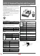
HS1C-P Interlock Plug Unit with Door Lock
Interlock plugs with door lock mechanism for high level safety management.
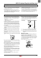
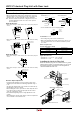
• Installing the actuator on the guard door and the interlock
switch on the machine, the guard door can be auto-locked
mechanically.
• Removing the interlock plug maintains the interrupted status
of load circuit and control circuit.
• Solenoid type and non-solenoid type available
• Solenoid type has a lock mechanism. Lock mechanism pre-
vents removal of interlock plug during machine operation, and
allows for removal after the machine has stopped, with sole-
noid energization signal.
• Flexible installation: The actuator can be inserted into two
direction.
• Rugged die-cast aluminum housing
• UL listed, c-UL listed.
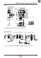
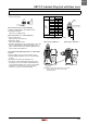
Interlock Plug Unit
Solenoid Part No.
With solenoid (24V DC)
HS1C-P44Z-
➁
Without solenoid
HS1C-P04Z-
➁
•Specify an indicator color code in place of
➁
in the Part No.
G: green, R: red
•Key wrench for TORX screws (HS9Z-T1) is supplied.
•Actuator is not supplied and must be ordered separately.
Actuators
Description Part No.
Straight Actuator
HS9Z-A1
Right-angle Actuator
HS9Z-A2
Angle Adjustable Actuator (for hinged doors)
HS9Z-A3
Key wrench for TORX screws
HA9Z-T1
Ratings
Circuit
Model
HS1C-P44Z HS1C-P04Z
Main
Circuit
Rated Insulation Voltage (Ui) 250V (100% duty cycle)
Rated Thermal Current (Ith) 10A
Monitor
Circuit
Rated Insulation Voltage (Ui) 250V
Rated Thermal Current (Ith) 3A
Rated Operating Voltage (Ue) 250V AC
Rated Operating Current (Ie)
0.1A
250V AC/
30V DC
(resistive load)
3A
(250V AC/
30V DC)
(resistive load)
Solenoid Unit
Rated Voltage 24V DC
Rated Current 260 mA
Coil Resistance
95Ω (at 20°C)
Pickup Voltage Rated voltage × 90% maximum (at 20°C)
Dropout Voltage Rated voltage × 10% minimum (at 20°C)
Maximum Continuous
Applicable Voltage
Rated voltage × 110%
Maximum Continuous
Applicable Time
Continuous
Power Consumption 6.3W
Indicator
Rated Voltage 24V DC
Rated Current 10 mA
Light Source LED
Lens Color G (green), R (red)
•The lens cannot be replaced.
Specifications
Applicable
Standards
Main Circuit
UL508 (UL listed)
CSA C22.2, No. 14 (c-UL listed)
UL498
CSA C22.2 No. 182.1
Auxiliary Circuit
UL508 (UL listed)
CSA C22.2, No. 14 (c-UL listed)
Applicable
Standards for
Use
EN 1088
Operating Temperature –20 to +50°C (no freezing)
Relative Humidity 45 to 85% (no condensation)
Storage Temperature –40 to +80°C (no freezing)
Pollution Degree 3
Insulation Resistance 100 MΩ minimum (500V DC megger)
Contact Resistance
100 mΩ maximum (initial value)
Dielectric Strength
Between live and dead metal parts:
2000V, 1 minute
Between terminals of the same poles:
1000V, 1 minute
Shock Resistance Damage limits: 1000 m/s
2
Vibration Resistance
Operating extremes:
10 to 55 Hz, amplitude 0.5 mm minimum
Damage limits: 30 Hz, amplitude 1.5 mm
minimum
Operating Frequency 900 operations per hour (actuator, plug)
Mechanical Life 30,000 operations minimum (actuator, plug)
Actuator Retention Force 1500N minimum
Interlock Plug Strength Rotational strength when locked: 5 N·m
Mounting Screw M5 × 4
Weight (approx.)
720g (HS1C-P44Z-
➁
)
Part No. Development
H S 1 C - P 4 4 Z - R
PL2 Indicator Color
G: Green, R: Red
Housing Color
Z: Beige only
Indicator Rated Voltage
4: 24V DC
Solenoid
4: With
0: Without