
Instruction Manual

123
HS1C-P Interlock Plug Unit with Door Lock
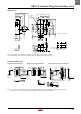
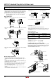
Dimensions
G1/2
Conduit
Port
23.5
54.3
68.8 36.5
40
22
45
49.5
125
26
4742
74
9
2 10
R2.7
ø5.4
40
106
75
1.5
ø5.2
±1
8.5
35
44
76
109
59
±1
6.5
4-M5 Screws
Mounting Hole Layout
23.5
42
47
26
Slot Plug
(Note)
31.2
7.5 4
4
5.5
4
*
*
* Actuator center position
Note: Plug the unused actuator entry slot using the slot plug supplied with the interlock switch.
•Use four mounting screws to mount the interlock switch according to the mounting hole layout.
49.39
1
2
4.1
43
18.3
29.2
R3.2
7.4
22
40
Actuator Cover
(red)
22
2-M6
Screws
Actuator
Mounting
Holes
10.511
1
20
R3.2
41.5
90°
7.4
22
40
29.2
43
4.1
2
22
Actuator
Mounting
Holes
Actuator Cover
(red) (Note)
2-M6
Screws
5
29.2
33 max.
2
(21)
18
20°
R
3.2
72
58
20
1
58
2
12
30
44
Door Hinge
Stopper Film
(Note)
2-M6 Screws
Angle Adjustment Screw
(M3 hexagon socket head screw)
Actuator
Mounting
Holes
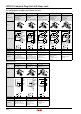
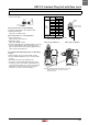
Actuator Dimensions
Straight Actuator HS9Z-A1 Right-angle Actuator HS9Z-A2 Angle-adjustable Actuator HS9Z-A3
Note: The actuator cover and actuator stop films are supplied with the actuator and used when adjusting the actuator position.
Remove the actuator cover and actuator stop film after the actuator position is determined.
HS1C-P