
Instruction Manual

127
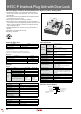
HS1C-P Interlock Plug Unit with Door Lock
Instructions
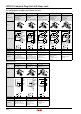
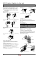
Applicable Cable Glands
•Use IP67 cable gland.
G1/2
9 mm max.
30 mm
max.
When Using Flexible Conduits (Example)
• Flexible conduit example: VF-03 (Nihon Flex)
• Metal gland example:
(G1/2)
RLC-103 (Nihon Flex)
When Using Multi-core Cables (Example)
• Plastic cable gland:
(G1/2) SCS-10
* (Seiwa Electric)
• Metal cable gland:
(G1/2) ALS-16 (Nihon Flex)
• Different cable glands are used depending on the cable
sheath outside diameter. When purchasing a cable
gland, confirm that the cable gland is applicable to the
cable sheath outside diameter.
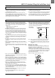
Recommended Tightening Torque of Mounting
Screws
• Interlock switch: 4.5 to 5.5 N·m (four M5 screws)
• Actuator (HS9Z-A1/A2/A3): 4.5 to 5.5 N·m (two M6
screws)
• Mounting bolts must be provided by users.
• The above recommended tightening torques of the
mount ing screws are the values confirmed with hex
socket head bolts. When other screws are used and
tightened to a smaller torque, make sure that the
screws do not come loose after mounting.
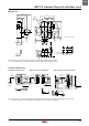
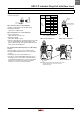
Cable Lead-in Length and Wiring Examples
Terminal
No.
Conduit Port
➀ ➁
Cable
Length
L1 (mm)
1 30±2 45±2
2 30±2 50±2
3 25±2 55±2
4 25±2 60±2
5 30±2 65±2
6 30±2 70±2
7 65±2 35±2
8 65±2 110±2
E 85±2 45±2
Wire Stripping Length
L2 (mm)
7±1
Note: Wire the interlock switches according
to the following examples.
Gland
L2 L1
Interlock Switch
When using Conduit Port ➁ When using Conduit Port ➀
Note: When wiring the ground (E) terminal, connect in the
solid line direction only. Do not connect in the
dotted line direction.
HS1C-P