
Instructions


B-1907-1(0)
INSTRUCTION SHEET - HS1L Series Solenoid Type Safety Switch
( 2 / 6 )
2016.08
3
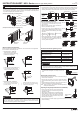
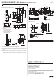
Mounting Examples
• Install the interlock switch on the immovable machine or guard, and install the
actuator on the movable door. Do not install both interlock switch and actuator on
themovable door, otherwise the angle of insertion of the actuator to the safety switch
may become inappropriate, and failure will occur.
• As shown below, the mounting reference position of the actuator inserted into the
safety switch is the actuator cover or stop film touches he safety switch lightly. (After
mounting the actuator, remove the actuator cover or stop film from the actuator.)
• Mounting tolerance of the actuator is 0.5mm
from the center of the actuator to up, down,
right, and, left.
• Make sure the actuator can be inserted into
the entry slot without any issue.
• Actuator can move 3.3mm (HS9Z-A1S and
-A2S) / 2.6mm (HS9Z-A3S) from the mounting
reference position without affecting the contact
operation.
• When closing the door, the actuator is inserted
and locked within approx. 3.8mm (HS9Z-A1S
and -A2S) / 3.3mm (HS9Z-A3S) from the
mounting reference position.
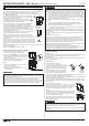
• Break a desired knockout to mount a connector using a
hammer and a screwdriver.
• Remove the connector lock nut from inside the safety
switch before breaking the knockout to open a connector
hole.
• When breaking the knockout to open a connector hole, be
careful not to damage the internal contact block.
Note : Cracks or burrs on the connector hole will degrade the
waterproof characteristics.
(
Examples of Mounting on Hinged Doors
)
Door
HS1L
Safety Switch
HS9Z-A1S
Actuator
Lock
Door Stop
Hinged
Door
HS1L
Safety Switch
Latch
HS9Z-A2S
Actuator
HS9Z-A1S
Actuator
(
Examples of Mounting on Sliding Doors
)
• L-shaped actuator : HS9Z-A2S
• Adjustable actuator : HS9Z-A3S
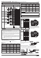
When using the safety switch for a hinged door, the minimum radius of the applicable
door is shown in the following figures.
Minimum Radius
270mm
Door Hinge
Minimum Radius
450mm
Door Hinge
When the center of the hinged door is
on he extension line of the contact
surface of actuator and safety switch.
( )
Minimum Radius
510mm
Door Hinge
Minimum Radius
840mm
Door Hinge
When the center of the hinged
door is on the extension line of the
actuator moun ing surfase.
( )
Minimum
Radius
80mm
Door Hinge
Minimum
Radius
50mm
Door Hinge
When the center of the hinged door is on
the extension line of the contact surface
of actuator and safety switch.
( )
When the center of the hinged door is
on the extension line of the actuator
mounting surfase.
( )
Minimum Radius of Hinged Door
Recommended Screw Tightening Torque
Opening the Connector Hole
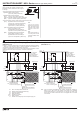
• Using the angle adjusting screw (M3 hexagon
socket head screw), the actuator angle can be
adjusted up to 20°.
• The larger the actuator angle, the smaller the appli-
cable radius of the door swing. After installing the
actuator, open the door. Then adjust the actuator
angle so that the actuator enters the entry slot of
the safety switch properly.
• After adjusting the actuator angle, apply loctite or the like on the adjusting screw to
prevent loosening.
Adjusting the Angle Adjustable Actuator (HS9Z-A3S)
Actuator Mounting Reference Position
Actuator Mounting Tolerance
HS9Z-A1S
Actuator
Cover
Safety Switch
Door Stop
Door Stop
Actuator
Cover
Safety SwitchSafety Switch
HS9Z-A2S HS9Z-A3S
Stop film
≤
3.3/ 2.6mm
+
Deviation of Deviation of
actuator position
door position
±0.5mm
±0.5mm
Center
Center
Safety
Switch
HS9Z-A1S
and -A2S
HS9Z-A3S
2.6mm
3.3mm
HS9Z-A1S
and -A2S
HS9Z-A3S
Approx.
3.8mm
Approx.
3.3mm
For mounting the safety switch (M5 screw) *6
For mounting the actuator
HS9Z-A1S, HS9Z-A2S (M5 screw) *6 *7
HS9Z-A3S (M6 screw)
For mounting the lid (M4)
Terminal screw (M3)
Connector
Angle adjusting screw of HS9Z-A3S
(M3 Hexagon Socket Head Screw)
Screw Tightening Torque
3.2 to 3.8 N•m
2.7 to 3.3 N•m
4.5 to 5.5 N•m
0.9 to 1.1 N•m
0.6 to 0.8 N•m
2.7 to 3.3 N•m
0.8 N•m
20°
Angle adjusting
screw
CAUTION
The figures shown above are based on the condition that the actuator enters and
exits the actuator entry slot smoothly when the door is closed or opened. Since
there may be deviation or dislocation of the hinged door, make sure of correct
operation in the actual application before installation.
CAUTION
*6 When the torque is not enough to recommended screw tightening torque, make
sure that the screw do not become loose by using adhesive sealants etc. to
keep right operation and mounting positioning.
*7 When rubber cushions (and spacers) are not used,
use M6 screws and tighten to a torque of 4.5 to 5.5
N•m.
Rubber Cushions