
Instructions


B-1907-1(0)
INSTRUCTION SHEET - HS1L Series Solenoid Type Safety Switch
( 4 / 6 )
2016.08
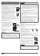
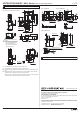
Contact Configuration and Operating Characteristic
Operation Cycle
5
Contact Operation
• Contact operation is based on the condition that the actuator is inserted into the
center of the safety switch slot.
• Contact operation shows the HS9Z-A1S, A2S, A3S actuator.
• Use main circuit or monitor circuit with for the input to safety circuit.
6
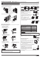
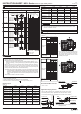
Wiring
Wire Stripping
Length: L2(mm)
Wire Length:
L1(mm)
Through Conduit Port
I
95±2
85±2
50±2
65±2
55±2
45±2
50±2
60±2
II
45±2
35±2
60±2
95±2
85±2
75±2
45±2
40±2
Wire Length inside the Safety Switch
7±1
11
21
32/34
42
52
62/64
A1
A2
Screw
Terminal
No.
X1
X2
70±2 35±2
80±2 35±2
35±2 60±2
61/63
45±2 70±2
51
75±2 35±2
31/33
60±2 70±2
22
* Do not remove the wires of the terminals
12-41 and 22-51, because these terminals
are interconnected in factory for safety
circuit inputs. Use terminals 11-42 or 21-52
for safety circuit inputs.
II
I
X2
X1
A2
A1
31/33
21
11
32/34
22
12
61/63
51
41
62/64
52
42
Safety Switch
Connector
L1L2
Applicable Crimping Terminal
Recommended Wire Core Size
: 0.5 to 1.5 mm
• N0.5-3/ FN0.5 (made by JST) :Applicable wire core size 0.2 to 0.5mm
2
• N1.25-MS3 (made by JST) : Applicable wire core size 0.25 to 1.65mm
2
• V1.25-YS3A (made by JST) : Applicable wire core size 0.25 to 1.65mm
2
4.2mm min.
L1
Φ3.2mm min.
6.4mm max.
Insulation Tube
Wire
Approx.4mm
Crimping
Terminal
Note: Make sure to use an insulation tube on the
crimping terminal.
Wire Stripping Length:
L2(mm)
Wire Length:
L1(mm)
Through Conduit Port
95±2
85±2
50±2
65±2
55±2
45±2
50±2
60±2
45±2
35±2
60±2
95±2
85±2
75±2
45±2
40±2
7±1
11
21
32/34
42
52
62/64
A1
A2
Screw
Terminal
No.
X1
X2
70±2 35±2
80±2 35±2
35±2 60±2
61/63
45±2 70±2
51
75±2 35±2
31/33
60±2 70±2
22
55±2 80±2
41
80±2 80±2
12
I II
I
II
X2
X1
A2
A1
31/33
21
11
32/34
22
12
61/63
51
41
62/64
52
42
11-42
61-62
31-32
21-52
11-42
21-52
33-34
63-64
21-22
11-42
33-34
51-52
61 62
31 32
21 22
63 64
3433
5251
2221
33 34
2221
41 421211
11 12 4241
41 421211
A2 A1
HS1L-R□
HS1L-DQ□
HS1L-DT□
Main Circuit :
Monitor Circuit :
Monitor Circuit :
Monitor Circuit :
Monitor Circuit :
Monitor Circuit :
Main Circuit :
Main Circuit :
Main Circuit :
Main Circuit :
Monitor Circuit :
Monitor Circuit :
61-62
6261
5251
51 52
Monitor Circuit :
X2
X1
*8
11-12
41-42
31-32
21-22
11-12
21-22
33-34
41-42
21-22
11-12
33-34
51-52
61 62
31 32
21 22
63 64
3433
5251
2221
33 34
2221
41 42
1211
11 12
4241
41 42
1211
HS1L-VR□
HS1L-VQ□
HS1L-VT□
Monitor Circuit :
Monitor Circuit :
Monitor Circuit :
Monitor Circuit :
Monitor Circuit :
Monitor Circuit :
Monitor Circuit :
Monitor Circuit :
Monitor Circuit :
Monitor Circuit :
Monitor Circuit :
Monitor Circuit :
61-62
6261
5251
51 52
Monitor Circuit :
Monitor Circuit :
41-42
51-52
63-64
Monitor Circuit :
Monitor Circuit :
61-62
51-52
Monitor Circuit :
Monitor Circuit :
Contact Closed
Contact Open
Door
monitor
Lock
monitorIndicator
Approx.4 2 (Lock)
0
(Actuator Mounting Reference Position)
(Travel : mm)
Operating Characteristic (reference)
Approx.
30.0
Approx.
10 0
(Actuator
Pulled Out)
(Actuator
Completely Inserted)
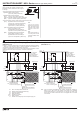
Contact Configuration*9
Approx.
7 0
Type
(
-
)(+)
(
+
)
(
-
)
Door States
Manual Unlock Key
Main Circuit 11-42
21-52
Monitor Circuit 21-22
31-32
Monitor Circuit 33-34
Monitor Circuit 51-52
61-62
Monitor Circuit 63-64
Spring Lock Type
(HS1L-□4)
Solenoid Power A1-A2
Solenoid Lock Type
(HS1L-□7Y)
Solenoid Power A1-A2
•Door is locked.
•The machine can
be operated.
Open
Open
Closed
•The machine can
not be operated.
Off / On *11
Closed
Closed
Open
•Door is unlocked.
•The machine can
not be operated.
Closed
Open
Closed
•Door is unlocked.
•The machine can
not be operated.
Off*10 *11
Closed
Open
to unlock position
Turn the key
Closed
On
Off
Closed
Closed
Closed
-
Off
On
Open
Closed
Open
-
Off / On
Open
Open
Open
-
Off
Open
Closed
Open
CAUTION
*8 This locking monitoring marking has been newly described in section 9.2.1 of
EN ISO/ ISO14119.It indicates that any devices with this marking meet the
following EN ISO/ ISO 14119 requirements:
- General (- General requirements for guard locking devices) (Section 5.7.1) *
- Locking monitoring (- Locking monitoring for guard locking devices) (Section
5.7.2.2)
When a lock monitor circuit (contact) has the locking monitoring marking, it
means that one circuit (contact) can monitor the position and the locking
function of the protective door. (The locking monitoring circuit (contact) turns
ON only when the protective door is closed and locked )
*note Both types of HS1L safety switches - spring lock type switches and solenoid
lock type switches - have obtained the locking monitoring cer ification marking.
Based on risk assessment results, solenoid lock type switches can be used
only for limited applications which do not especially need to be locked for
safety.
*9 The Actuator is inserted , and HS1L is locked.
CAUTION
*10 Do not attempt manual unlocking when the solenoid is energized.
*11 Do not energize the solenoid for a long time while the door is open or when
the door is unlocked manually.
(
HS1L-□
)
Door States
Manual Unlock Key
Monitor Circuit 11-12
21-22
31-32
Monitor Circuit 33-34
Monitor Circuit 41-42
51-52
61-62
Monitor Circuit 63-64
Spring Lock Type (HS1L-□4)
Solenoid Power A1-A2
Solenoid Lock Type (HS1L-□7Y)
Solenoid Power A1-A2
•Door is locked.
•The machine can
be operated.
Open
Closed
Open
Closed
Closed
•The machine can
not be operated.
*11
Off / On
Closed
Open
Closed
Open
Open
•Door is unlocked.
•The machine can
not be operated.
Closed
Open
Open
Closed
Closed
•Door is unlocked.
•The machine can
not be operated.
*10 *11
Off
Closed
Open
Open
Closed
to unlock position
Turn the key
Closed
On
Off
-
Off
On
-
Off / On
-
Off
(
HS1L-V□
)
(
HS1L-V□
)
(
HS1L-□
)