
Instructions


B-1907-1(0)
INSTRUCTION SHEET - HS1L Series Solenoid Type Safety Switch
( 5 / 6 )
2016.08
7
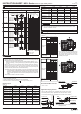
Example of wiring Diagram realizing Safety Category
DC24V
S3
F1
K4
K3
DC0V
A1(
-
)
A2(+)
52
S1
12
11
HR1S-AF Safety relay module
13
14
ESC
K4
K3
S2
51
42
41
22
21
S33 S34 13 23A1
S11 S22
14 24A2
S12S21
34
33
62
61
DC24V
S3
F1
K4
K3
DC0V
HR1S-AF Safety relay module
13
14
ESC
K4
K3
S2
S33 S34 13 23A1
S11 S22
14 24
S12S21
S4
1
2
A1(
-
)
A2(+)
52
S1
12
11
51
42
41
22
21
A2
34
33
62
61
L1(+)
N(−)
L1(+)
N(−)
One of the example of
the circuit ; Safety
relay module, HR1S-AF
series manufactured
by IDEC CORPORATION
Output Circuit Output Circuit
One of the example of
the circuit ; Safety
relay module, HR1S-AF
series manufactured
by IDEC CORPORATION
Used as
open/close
monitor of guard
Used as
open/close
monitor of guard
S1: HS1L-R4 Safety Switch with Solenoid
S2: Starting Switch (HW Series Momentary)
S3: Unlocking Enabling Switch
S4: Safety limit Switch
ESC:
Outside start condition
K3, 4: Safety Contactor
F1:
Outside fuse of safety relay module at power supply line
Note: Use the monitoring device(Safety relay module) provided the capavility to
detect a cross short circuit. The insulation of the cable has to withstand
environmental influences. If a control device o her than the one shown in the
draft is used, the used control device has to be equipped with a cross short
circuit monitor.
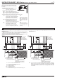
Guard Open
Guard Open
HS9Z-A1S Actuator
HS9Z-A1S Actuator
HS1L-R4
Safety Switch with Solenoid
HS1L-R4
Safety Switch with Solenoid
Example of a circuit diagram for Safety Category 4
(attainable PL = e)
Example of a circuit diagram for Safety Category 3
(attainable PL = d)
(Condition 1: To apply the fault exclusion of mechanical structural parts including the actuator
→ Make sure to use the product within he product specification range described in his
manual and the version of the manual provided wi h the product.)
(Condition 2: Documentation of the reason for the machine/equipment manufacturer to have
applied the fault exclusion based on ISO13849-1, ISO13849-2 or IEC62061.)
Used as
lock / unlock
monitor
Used as
lock / Unlock
monitor
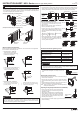
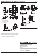
Applicable Connectors
Use a connector with a degree of protection IP67.
Applicable connector dimensions: See the figure
on the right.
9mm max.
Conduit Thread
30mm max.
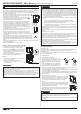
• When using flexible conduit and metal connector
Applicable Flexible Conduit Example:
Type VF-03 (made by Nihon Flex)
Applicable Metal Connector Example:
(G1/2) Type RLC-103 (made by Nihon Flex)
(PG13.5) Type RBC-103PG13.5 (made by Nihon Flex)
(M20) Type RLC-103EC20 (made by Nihon Flex)
• When using plastic connector, metal connector and multi-core cable
(G1/2) Applicable Plastic Connector Example :
Type SCS-10
□ (made by Seiwa Electric)
Applicable Metal Connector Example :
Type ALS-16
□□ (made by Nihon Frex)
(PG13.5) Applicable Plastic Connector Example :
Type ST13.5(made by LAPP)
Applicable Metal Connector Example :
Type ABS-
□□PG13.5(made by Nihon Flex)
(M20) Applicable Plastic Connector Example :
Type ST-M20×1.5(made by LAPP)
Applicable Metal Connector Example :
Type ALS-
□□EC20(made by Nihon Flex)
Note :
Confirm the outside
diameter of the multi-core
cable, the connector type
depends on the outside
diameter of multi-core
cable.
Note :
When using ST-M20×1.5,
use with gasket GP-M
(Type No: GPM20, made
by LAPP).