
Instructions


B-1907-1(0)
INSTRUCTION SHEET - HS1L Series Solenoid Type Safety Switch
( 6 / 6 )
2016.08
8
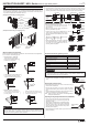
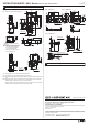
Dimensions (mm)
Type : HS9Z-A1S
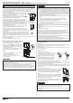
Type : HS9Z-A2S
Type : HS9Z-A3S
Actuator cover
(supplied)
Accessories dimensions
RP: Actuator mounting reference position
Safety Switch dimensions
9
Precaution for Disposal
Dispose of the HS1L safety switch as an industrial waste.
http://www.idec.com
Manufacturer: IDEC CORP.
2-6-64 Nishimiyahara Yodogawa-ku, Osaka 532-0004, Japan
EU Authorized Representative:IDEC Elektrotechnik GmbH
Heselstuecken 8, D-22453 Hamburg, Germany
DECLARATION OF CONFORMITY
We, IDEC CORPORATION 2-6-64, Nishimiyahara Yodogawa-ku,Osaka 532-0004, Japan declare
under our sole responsibility that the product:
Description: Safety Switch
Model No: HS1L
to which this declaration relates is in conformity with the EC Directive on the following standard(s)
or other normative document(s). In case of alteration of the product, not agreed upon by us, this
declaration will lose its validity.
Applicable EC Directive : Low Voltage Directive (2014/35/EU)
Machinery Directive (2006/42/EC)
Applicable Standard(s) : EN 60947-5-1,GS-ET-19
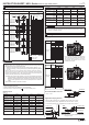
Slot Plug
(Supplied)
*12 The actuator entry slot vertical to the mounting panel
*13 The actuator entry slot horizontal to the mounting panel
Note: Use the slot plug attached to the safety switch to close the unused actuator entry
slot.
Note: When the actuator entry slot vertical to the mounting panel is used : Install the
interlock switch on the panel using four mounting screws.
When the actuator entry slot horizontal to the mounting panel is used : Install the
interlock switch on the panel using three mounting screws.
21
±0.5
17.5
±0.5
(51.3)
11.5
(65.8)(RP)
(RP)
HS9Z-A2S
61
12.3
4-M5
screw
23.5
*33.5
26
89
HS9Z-A1S
33
88
4
104
7.5
2
49.5
51
70.3
(RP)
45.4
4
5 5
35
1.5
10
121
129
26
23.5
45
63
5
19.2
22
89
10
36
55 8
(RP)
(3.5
±0.5
)
(7.0
±0.5
)
4
5
*13
*12
40
5.4
44.5
21
22
2-M5
90°
5.1
(8)
3
17.6
43
40
(45.1)
42 6
0.8
12.3
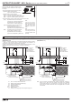
Stopper film
2-M6
20°
(21)
33max.
2
30
5
12
18
3
R3.2
72
58
44
58
17.6
20
(supplied)
22
40
9 49.3
43
17.6
3
(8)
5.1
Φ15.0
Φ5.1
0.8
19.3
Φ15
Φ5.1
22
11 5
20.5
Safety switch Mounting Hole
Layout
* Use this mounting hole when
a strong actuator retention
force is imposed to the
actuator entry slot vertical to
the mounting panel.
Mounting Hole Layout
Mounting Hole Layout
Angle ajusting screw
(M3 hexagon socket set screw)