
Datasheet


Flush Silhouette Switches LB Series Illuminated Selector Switches
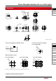
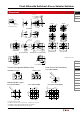
Dimensions
All dimensions in mm.
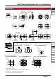
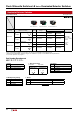
Mounting Hole Layout
Round (LB6F/LB6MF)
Note: When using terminal cover, see dimensions on page 58.
ø18.2
+0.2
0
22 min
22 min
•For details on pc board and circuit design, see page 50.
•For details on single board mounting, see page 51.
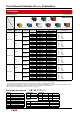
Illuminated
Pushbutton
Pilot Light
Pushbutton
Selector
Illuminated
Selector
Key Selector
Lever Switch
Buzzer
Accessories
Maintenance
Parts
Panel
Cut-out
Instructions
Flush Silhouette
LB Series
Flush Silhouette
LBW Series
ø16
LB Series
UP Series
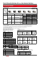
Round (LB6F/LB6MF)
Panel Cut-out for Positioning
4-R0.5 or
less
ø18.2
±0.1
1.9
±0.05
17.1
±0.05
17
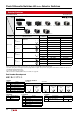
Terminal Arrangement (Bottom View)
ø22
7 2.4
27.9
1
6 6
10.3
∗
1.2
1
2.6
2-R0.6
∗ Solder/Tab Terminal
Panel Thickness:
0.5 to 3.2 mm
Gasket
Locking Ring
Mounting
Bracket
2.8W × 0.5t
Round
3.856.95
17.8
15.8
17.8
LOCK
3 3
5 5
2
5.5
1
0.8W × 0.5t
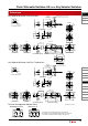
[PC Board Terminal] [Solder/Tab Terminal]
6.95 3.85
(SPDT contacts on the right only)
X1
X2
11
14
12
24
22
21
Lamp
Te rminal (+)
Lamp
Te rminal (−)
X2
X1
Lamp
Te rminal (+)
Lamp
Te rminal (−)
TOP
TOP