
Datasheet

51
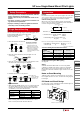
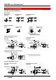
Installing and Removing Contact Blocks
Turn the locking lever to install and remove contact blocks
on the PC using a screwdriver from a hole in the PC board.
See "Notes for Designing PC Board and Circuit" on page 50.
Determine the location of the switches so that the locking
lever can be operated. See "Removing and Installing the
Contact Block" on page 61.
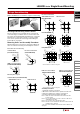
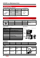
Mounting Holes and Assembly Procedure
Drill mounting holes in the panel as shown below. When the
units are mounted collectively, provide adequate clearance.
IDEC’s LB/LBW Series is available for single board mounting.
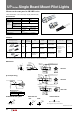
Assembly Procedure
1. Install the operator to the panel.
2. Mount the contact block to the operator from the rear.
3. Turn the locking lever to lock the contact block.
4. Insert the PC board to terminals and solder.
Note 1: Make sure that each terminal is inserted into the PC
board correctly.
Note 2: Do not apply tensile force to the connector cable for an
extended period of time.
Note 3: Do not expose the contact block to water.
Note 4: Ensure to lock contact blocks when the contact blocks are
installed on the operators.
UP series can be installed on the same board. For details, see
page 52.
ø6 drilled hole
for operating the
locking lever
RearFront
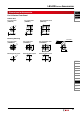
LB/LBW Series Single Board Mounting
Single Board Mounting
ø16.0
0
+
0.1
0.05
0.05
1.9
14.8
+_
+_
ø16.
0
+0.1
0
ø16.0
+0.1
0
(24 or more for
rectangular units)
(24 or more for
rectangular units)
18
or more
21
or more
23.2
or more
18
or more
1.9
0
−0.1
21.6
ø22.3
+0.2
0
+0.1
0
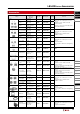
LBW Series Flush Bezel
(LBW6/LBW6M/LBW6G)
SPDT/DPDT Contacts 3PDT Contacts
Standard Bezel (LB1/LB2/LB3/LB4)
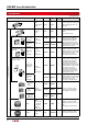
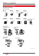
Panel Cut-out for Positioning
Mounting Hole Layout
Standard Bezel
(LB1/LB2/LB3/LB4)
LB Series Flush Bezel
(LB6/LB6M/LB6G)
LB Series Flush Bezel
SPDT/DPDT Contacts 3PDT Contacts
24.2
±0.1
18.2
±0.1
18.2
±0.1
24.2
±0.1
18.2
±0.1
18.2
±0.1
ø18.2
±0.1
ø18.2
±0.1
22 min
22 min
28 min
28 min
22 min
∗
22 min
∗
22 min
∗
22 min
∗
22 min
∗
22 min
∗
23.2 min
23.2 min
* 45 mm minimum for switches with guard
4-R0.5 or
less
ø18.2
±0.1
1.9
±0.05
17.1
±0.05
26 min.
26 min.
22.5
26 min.
26 min.
+0.2
0.0
ø22.3
+0.2
0.0
* 53 mm minimum for switches with guard
LBW Series Flush Bezel
LBW Series Flush Bezela
LBW6/LBW6M/LBW6G
LB6/LB6M/LB6G
LB7/LB7M/LB7G
LB8/LB8M/LB8G
LBW7/LBW7M/LBW7G
26 min.
26 min.
22.5
26 min.
26 min.
+0.2
0.0
ø22.3
+0.2
0.0
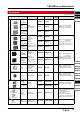
Illuminated
Pushbutton
Pilot Light
Pushbutton
Selector
Illuminated
Selector
Key Selector
Lever Switch
Buzzer
Accessories
Maintenance
Parts
Panel
Cut-out
Instructions
Flush Silhouette
LB Series
Flush Silhouette
LBW Series
ø16
LB Series
UP Series