
Information


EF1A Flameproof LED Illumination Units
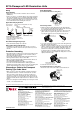
Wiring
Applicable Wire
•Stranded wire: 0.5 to 2.0 mm
2
, Solid wire: ø0.5 to ø2.0 mm
2
(AWG16-12)
•Connect one wire to one terminal. When connecting an insulated
wire to the terminal block, use a crimping terminal with insulation
sheath. Bare crimping terminal must be insulated with an insula-
tion tube or making tube. Make sure not to apply excessive force
to the terminal block when installing the end cover.
Applicable Crimping Terminal
Screw Terminal
(Ring Terminal)
Spring Clamp Terminal (WAGO: 741-302)
6.0 max
5.3 min
ø
3.2 min.
Without
insulation sheath
With
insulation sheath
Reccomended ferrule (WAGO)
Ferrule with insulation sheath: 216-204
Ferrule without insulation sheath: 216-104
Crimping too: 206-204
Insulation
Sheath
Wire
8.0 max
1.8 max
(Dimension after crimping)
8.0 max.
1.8 max
(Ferrule)
Recommended Tightening Torque
•Screw terminal block (M3): 0.5 to 0.8 N·m
Wiring Cable Grand on Both Ends
•A maximum of four EF1A can be connected. Do not connect
more than four EF1As, otherwise the input current may exceed
the limit.
Protective Grounding
•Ground the EF1A according to the environment and ratings of the
application. Observe the regulations of the relevant country or
region where the EF1A is used.
•Use the M4 grounding terminal inside the EF1A and make sure
that the ground resistance value is under 100.
•When not using the M4 grounding terminal inside the EF1A, use
the external M4 grounding terminal.
Recommended tightening torque (M4): 1.4 to 2.0 N·m.
•Use a wire in size and material which is durable against the
maximum expected grounding current. Protect the grounding wire
against external damage by encasing in a metal conduit.
Connecting a Cable to the Flameproof
Packing Type Cable Gland
•When choosing a cable, take maximum operating temperature
and chemical resistance of insulator and sheath into consider-
ation. The inside of cable must be as solid as possible to pre-
vent ingress of explosive gas through the cable, and smooth on
surface and round in cross-section. When choosing the size and
insulation material, take the temperature rise of cable into consid-
eration.
•Protect the cable against external damage by encasing in a metal
conduit, or in a metal/cement duct.
Parts Description
(Part number without W on cable gland)
Gasket
Washer
Nut
Ring
End Cover
Clamp Plate
Gland
Gland Set Screw
Connecting a Cable
1. Make sure that the cable gland matches the cable diameter.
If not, replace the cable. Or replace the EF1A with one that has
the cable gland with matching cable diameter.
2. Remove the parts from the end cover in the order of nut, ring,
gland, washer, and gasket. The gland can be removed by
loosening the gland set screw using the hex key (size 2).
Hex Key (size 2)
Cable
3. Loosen the clamp plate screws. Pass the cable through the nut,
ring, gland, washer, and gasket.
4. Place the gasket and washer in the end cover, and screw in the
gland to compress the gasket. Tighten the gland until the cable
does not move when pulled out lightly, and tighten further one
full turn. If the clamp plate is in the posture which is difficult to
be approached by a screwdriver, turn the gland for ±1/3 turn.
Tighten the gland set screw. Tighten the clamp plate set screws
equally to fixate the cable.
Gland Set Screw
Clamp Plate Screw
5. Screw the nut into the end cover.
(Part number without W on cable gland)
•Connect the cable in the same manner as described above.
Gasket
Clamp Plate
Gland
End Cover
Washer
Gland Set Screw
IDEC CORPORATION (USA)
1175 Elko Drive
Sunnyvale, CA 94089-2209, USA
Tel: +1-408-747-0550 / (800) 262-IDEC (4332)
Fax: +1-408-744-9055 / (800) 635-6246
E-mail: opencontact@idec.com
IDEC CANADA LIMITED
3155 Pepper Mill Court, Unit 4
Mississauga, Ontario, L5L 4X7, Canada
Tel: +1-905-890-8561
Toll Free: (800) 262-IDEC (4332)
Fax: +1-905-890-8562
E-mail: sales@ca.idec.com
IDEC AUSTRALIA PTY. LT D.
Unit 17, 104 Ferntree Gully Road,
Oakleigh, Victoria 3166, Australia
Tel: +61-3-8523-5900, Toll Free: 1800-68-4332
Fax: +61-3-8523-5999
E-mail: sales@au.idec.com
7-31, Nishi-Miyahara 1-Chome, Yodogawa-ku, Osaka 532-8550, Japan
Tel: +81-6-6398-2571, Fax: +81-6-6392-9731
E-mail: marketing@idec.co.jp
Specifications and other descriptions in this catalog are subject to change without notice.
Cat. No. EP1476-0 FEBRUARY 2013 PDF
IDEC ELECTRONICS LIMITED
Unit 2, Beechwood, Chineham Business Park,
Basingstoke, Hampshire RG24 8WA, UK
Tel: +44-1256-321000, Fax: +44-1256-327755
E-mail: sales@uk.idec.com
IDEC ELEKTROTECHNIK GmbH
Wendenstrasse 331, 20537 Hamburg, Germany
Tel: +49-40-25 30 54 - 0, Fax: +49-40-25 30 54 - 24
E-mail: service@idec.de
IDEC (SHANGHAI) CORPORATION
Room 701-702 Chong Hing Finance Center,
No. 288 Nanjing Road West, Shanghai 200003, PRC
Tel: +86-21-6135-1515
Fax: +86-21-6135-6225 / +86-21-6135-6226
E-mail: idec@cn.idec.com
IDEC (BEIJING) CORPORATION
Room 211B, Tower B, The Grand Pacific Building,
8A Guanghua Road, Chaoyang District,
Beijing 100026, PRC
Tel: +86-10-6581-6131, Fax: +86-10-6581-5119
IDEC (SHENZHEN) CORPORATION
Unit AB-3B2, Tian Xiang Building, Tian’an Cyber Park,
Fu Tian District, Shenzhen, Guang Dong 518040, PRC
Tel: +86-755-8356-2977, Fax: +86-755-8356-2944
IDEC IZUMI (H.K.) CO., LTD.
Units 11-15, Level 27, Tower 1,
Millennium City 1, 388 Kwun Tong Road,
Kwun Tong, Kowloon, Hong Kong
Tel: +852-2803-8989, Fax: +852-2565-0171
E-mail: info@hk.idec.com
IDEC TAIWAN CORPORATION
8F-1, No. 79, Hsin Tai Wu Road, Sec. 1,
Hsi-Chih District, 22101 New Taipei City, Taiwan
Tel: +886-2-2698-3929, Fax: +886-2-2698-3931
E-mail: service@tw.idec.com
IDEC IZUMI ASIA PTE. LT D.
No. 31, Tannery Lane #05-01,
HB Centre 2, Singapore 347788
Tel: +65-6746-1155, Fax: +65-6844-5995
E-mail: info@sg.idec.com
www.idec.com
(13/02/15)