
Information


2524
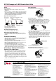
LF Series Adjustable Angle Mounting Bracket
Mounting angle can be adjusted from 0° to 90°.
LED illumination units can be installed exibly.
•Mounting angle can be adjusted from 0° to 90° in 10° incre-
ments, providing more options for mounting of the LED illumina-
tion units.
•Illumination angle can be adjusted to suit the operator in various
applications, such as visual inspection.
Application Example
LF9Z-1MB1
LF9Z-1MDE1
LF9Z-1MDF1
Hexagonal
bolt
Adjustable Angle Mounting Bracket
Adjustable Angle
Mounting Bracket for
LF1D/LF1B
Part No. Applicable LED Illumination Unit Material Package Quantity
LF9Z-1MDE1
LF1D-E
Stainless Steel
1 pair (right and left)
(mounting screws supplied)
LF9Z-1MDF1
LF1D-F
LF9Z-1MB1
LF1B-A, -B, -C (not -D)
Part No. E F G
LF9Z-1MDE1
25
±0.2
374
±2.0
4-M5
LF9Z-1MDF1
40
±0.2
292
+4.0
4-M5
LF9Z-1MB1
14 (Note) 4-M4
Note: Same as the mounting hole centers of LED illumination units.
–2.0
LF9Z-1MB1
•Use the attached hexagonal bolts to fix the LF1D at the desired angle.
•See specifications of the LF1D for operating environment and mechanical strength.
All dimensions in mm.
Dimensions
28
(73)
90°
53
50 13
36
66
R45
90°
62
36
(87.5)
975
27.5
77
R60
LF9Z-1MDE1 LF9Z-1MDF1
Mounting Hole Layout
4-M5 screws
B
A
50.5
90°
35.2
27
27.5
Safety Precautions
Instructions
•LED modules may vary in illumination colors and illuminance.
•Before designing equipment and powering up illumination units, confirm the
specifications described in the instruction sheet.
•Apply voltage within the rated value, otherwise the LED elements may be
damaged.
•The illumination unit is vulnerable to static electricity. Take sufficient
measure for protection against static electricity and voltage surges.
•Make sure that the illumination unit does not fall during transportation,
installation, and operation, otherwise damage may result.
•Do not pull or push the cable of the illumination unit, otherwise damage
may result. Allow sufficient slack to the cable while wiring.
•Do not apply excessive force. Do not leave a damaged illumination unit
unattended or use a damaged illumination unit.
•Ensure the correct operating temperature. Otherwise internal temperature
rise may result in damage.
•Do not use or store in a place subjected to vibration and shock.
•Do not use in the following places:
* Exposed to direct sunlight, near heaters, high temperatures
* Subject to chemicals, and corrosive gases
(Plastic illumination surface: Iron powder and oil)
* Basements, greenhouses, or other humid places
* Cold storage warehouses (make sure that no freezing occurs)
•Do not loosen screws, otherwise the protection characteristics will be
impaired.
•For the LF2D illumination units, make sure to provide sufficient strength for
mounting panel. Required waterproof characteristics cannot be obtained if
a distorted mounting panel is used.
•To clean the cover, use a soft cloth with water or neutral detergent.
Do not use solvents such as thinners, benzene, or alkaline, otherwise
discoloration, deterioration, or decrease in strength may occur.
•The edge of the cable sheath is not waterproof construction. Water may
invade the LF1B in a capillary action when water splashes directly onto the
cable sheath.
•Do not disassemble, repair, or modify the LED illumination unit. Otherwise
electric shock, fire, or malfunction may occur.
•Turn off power before wiring. Make sure of correct wiring, otherwise electric
shock or damage may result.
•Do not stare directly into the LED illumination unit while it is lit, and do not
project the light to other people, otherwise eyes may be injured.
•LED illumination unit is general-purpose industrial electric device. Do
not use for electronic equipment which may damage the human body or
threaten life in case a malfunction or failure occurs.
•Ensure that the cable does not touch the LED illumination unit.
LF Series LED Illumination Units
TM
EF1A Flameproof LED Illumination Units
Can be used in hazardous area of Zone 1
and 2, where hydrogen or acetylene gas are
present.
•Various mounting styles.
•Condensing or diffused light distribution characteristics.
•Screw terminal, spring clamp terminal, and lead wire connec-
tion are available.
•IP67 (IEC 60529)
Ex d II CT4
Explosion-proof
Class
Specifications
Part No. EF1A-12 EF1A-11
Explosion Protection Ex d IIC T4
Installation Area Zone 1, Zone 2
Rated Voltage 100 to 240V AC 24V DC
Voltage Range 90 to 264V AC 18 to 26.4V DC
Power Consumption
(typ.) (at rated voltage)
19W 16W
Insulation Resistance
100M minimum (500V DC megger)
(between input and ground)
Dielectric Strength 2,000V AC, 1 minute (between input and ground)
Vibration Resistance
(damage limits)
Frequency 5 to 55 Hz, amplitude 0.5mm
Shock Resistance
(damage limits)
1,000 m/s
2
Operating Temperature –20 to +50°C (no freezing)
Operating Humidity 45 to 85% RH (no condensation)
Storage Temperature –35 to +70°C (no freezing)
Service Life (Note)
Approx. 50,000 hours minimum
(The total illumination duration where the illumi-
nance maintains a minimum of 70% of the initial
value in 25°C environment.)
Degree of Protection IP67 (IEC 60529), IP65 (with ON/OFF switch)
Material
Housing: aluminium, front panel/mounting bracket:
stainless steel, illumination surface: reinforced
glass, cable gland: nickel-plated brass
Weight (approx.)
3.2kg (direct mounting)
3.4kg (with mounting bracket)
Note: LED life depends on the operating environment.
Input
Light
Distribution
Mounting Bracket
Cable Clamp
Waterproof
Illumination Surface
Terminal Block
Applicable Cable
Diameter
Part No.
100 to 240V AC
Condensing
Direct Mounting
Ye s
Clear glass: Blank
Translucent glass: 1
Spring clamp: Blank
Screw: S
Lead wire: C
10: ø8 to ø10
12: ø10 to ø12
14: ø12 to ø14
16: ø14 to ø16
EF1A-12W-
No
EF1A-12W-W
Mounting Bracket
Ye s
EF1A-12WA-
No
EF1A-12WA-W
Angle Adjustable
Mounting Bracket
Ye s
EF1A-12WB-
No
EF1A-12WB-W
Diffused
Direct Mounting
Ye s
EF1A-12W1-
No
EF1A-12W1-W
Mounting Bracket
Ye s
EF1A-12W1A-
No
EF1A-12W1A-W
Angle Adjustable
Mounting Bracket
Ye s
EF1A-12W1B-
No
EF1A-12W1B-W
24V DC
Condensing
Direct Mounting
Ye s
EF1A-11W-
No
EF1A-11W-W
Mounting Bracket
Ye s
EF1A-11WA-
No
EF1A-11WA-W
Angle Adjustable
Mounting Bracket
Ye s
EF1A-11WB-
No
EF1A-11WB-W
Diffused
Direct Mounting
Ye s
EF1A-11W1-
No
EF1A-11W1-W
Mounting Bracket
Ye s
EF1A-11W1A-
No
EF1A-11W1A-W
Angle Adjustable
Mounting Bracket
Ye s
EF1A-11W1B-
No
EF1A-11W1B-W
• Specify "T" before in the part number for both input and output ends to have a cable gland. Applicable cable diameter is the same for both ends.
Part No. example: EF1A-12WT-10
• Specify “P” before and “-A2” at the end of the part number when the input end has cable gland and the output end has ON/OFF switch.
Part No. example: EF1A-121W1P-10-A2
Part No. Development
E F 1 A – 1 1
1 W
1 P S A – 12 W – A2
Rated Voltage
1: 24VDC
2: Universal voltage
(100 to 240V AC)
ON/OFF switch
A2: extended
(maintained)
Illumination Surface
Blank: Clear glass
1: Translucent glass
Light Distribution
Blank: Condensing light
(with lens)
1: Diffused light
(without lens)
Cable gland
Blank:
Clamp with waterproof
W:
Clamp without waterproof
Applicable Cable Diameter
10: ø to 10 (G1/2)
12:ø10 to 12 (G1/2)
14:ø12 to 14 (G3/4)
16:ø14 to 16 (G3/4)
Cable gland & ON/OFF switch
Blank: Cable gland on one end/
without ON/OFF switch
T: Cable gland on both ends/
without ON/OFF switch
P: Cable gland on one end/
with ON/OFF switch
Terminal Block
Blank: Spring clamp terminal block
S: Screw terminal block
C: Lead wire
Mounting Bracket
Blank: Without (direct mounting)
A: With mounting bracket
B: Angle adjustable mounting
bracket
Package quantity: 1
TM
(13/02/15) (13/02/15)