FC9Y-B1283 FC5A SERIES PID Module User’s Manual
SAFETY PRECAUTIONS • Read this user’s manual to make sure of correct operation before starting installation, wiring, operation, maintenance, and inspection of the FC5A series MicroSmart PID modules. • All MicroSmart modules are manufactured under IDEC’s rigorous quality control system, but users must add a backup or failsafe provision to the control system using the MicroSmart in applications where heavy damage or personal injury may be caused in case the MicroSmart should fail.
• Use an EU-approved circuit breaker. This is required when equipment containing the MicroSmart is destined for Europe. • Make sure of safety before starting and stopping the MicroSmart or when operating the MicroSmart to force outputs on or off. Incorrect operation on the MicroSmart may cause machine damage or accidents. • If relays or transistors in the MicroSmart output modules should fail, outputs may remain on or off.
ABOUT THIS MANUAL Thank you for purchasing FC5A series MicroSmart PID Module. This user’s manual primarily describes system configuration, specifications, installation, programming, application examples, and trouble shooting of the PID module. Read this user’s manual to ensure the correct understanding of the entire functions of the PID module. NOTICE 1.
REVISION HISTORY Revision history of this user’s manual is described here. Date March, 2011 iv Manual No.
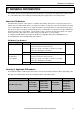
RELATED MANUALS The following manuals related to the FC5A series MicroSmart are available. Refer to them in conjunction with this manual. Type No. Manual Name Description FC9Y‐B1283 FC5A Series PID Module User's Manual (this manual) Describes PID Module specifications and functions.
vi FC5A MicroSmart PID Module User’s Manual FC9Y-B1283
TABLE OF CONTENTS CHAPTER 1: GENERAL INFORMATION ...................................................................................... 1-1 About the PID Modules .................................................................................................................................... 1-1 Quantity of Applicable PID modules ................................................................................................................ 1-1 Applicable CPU and WindLDR version ..........................
CHAPTER 6: CONFIGURING PID MODULE USING WINDLDR .................................................... 6-1 Procedure to configure the PID module .......................................................................................................... 6-1 Expansion Modules Configuration Dialog Box ................................................................................................ 6-6 PID Module Configuration Dialog Box ..............................................................................
GENERAL INFORMATION 1: GENERAL INFORMATION This chapter describes general information and specifications of the FC5A series PID modules. Make effective use of the PID modules after reading and understanding thoroughly functions and characteristics. About the PID Modules The PID module performs control actions to eliminate the deviation between the set point (SP) and process variable (PV). The PID module, which is an expansion module, is required to connect to the FC5A series CPU for use.
GENERAL INFORMATION Applicable CPU and WindLDR version PID modules can be used with the following FC5A CPU module system program version and WindLDR version as listed below. Type All-in-One Type FC5A-C10R2 FC5A MicroSmart CPU FC5A-C10R2C FC5A-C10R2D Slim Type FC5A-C16R2 FC5A-C16R2C FC5A-C24R2 FC5A-C16R2D FC5A-C24R2C FC5A-C24R2D CPU System Program Version WindLDR Version FC5A-D16RK1 FC5A-D16RS1 FC5A-D32K3 FC5A-D32S3 FC5A-D12K1E FC5A-D12S1E 230 or higher *1 6.
MODULE SPECIFICATIONS 2: MODULE SPECIFICATIONS This chapter describes parts names, functions, specifications, and dimensions of the PID modules.
MODULE SPECIFICATIONS (3) Control Output LED (OUT0, OUT1) ON : Control output is turned on. OFF : Control output is turned off. Flashes : When current output is used, the LED flashes in a cycle of 125 ms according to the duty ratio of the output manipulated variable (MV). When output manipulated variable (MV) is 20%, the LED turns on for 25 ms and off for 100 ms continuously. (4) Event Output LED (EVT0, EVT1) ON : Any alarm out of alarm 1 to alarm 8, loop break alarm is triggered.
MODULE SPECIFICATIONS Specifications PID Module Specifications Rating Type No. FC5A-F2MR2 FC5A-F2M2 Thermocouple Type K K (with decimal point) J R S B E T N PL-II C(W/Re5-26) Measurement Range -200 to 1370°C -200.0 to 400.0°C -200 to 1000°C 0 to 1760°C 0 to 1760°C 0 to 1820°C -200 to 800°C -200.0 to 400.0°C -200 to 1300°C 0 to 1390°C 0 to 2315°C -328 to 2498°F -328.0 to 752.0°F -328 to 1832°F 32 to 3200°F 32 to 3200°F 32 to 3308°F -328 to 1472°F -328.0 to 752.
MODULE SPECIFICATIONS General Specifications Type No. FC5A-F2MR2 Connector on Mother Board Connector Insertion/Removal Durability Connector FC5A-F2M2 Input : F6018-17P (Fujicon) Output : F6018-11P (Fujicon) Input Specifications Type No. FC5A-F2MR2 Thermocouple Maximum Error at 25°C Resistance Thermometer Voltage, Current Thermocouple Input Accuracy (at 0 to 55°C) Resistance Thermometer Voltage, Current Data Accuracy Cold Junction Temperature Compensation Accuracy Sampling Period FC5A-F2M2 ±0.
MODULE SPECIFICATIONS Insulation, Dielectric Strength Insulation, Dielectric Strength Type No.
MODULE SPECIFICATIONS 4.5* Dimensions (All dimensions in mm) * 8.
INSTALLATION AND WIRING 3: INSTALLATION AND WIRING This chapter describes how to install and wire the PID modules. For general methods and precautions for installation and wiring of the PID modules, see chapter 3 in the FC5A MicroSmart user’s manual (FC9Y-B1268). Be sure to use the PID modules properly after understanding installation and wiring thoroughly. Caution • Assemble the CPU module and PID modules before installing them on a DIN rail. Otherwise, they may break.
INSTALLATION AND WIRING Example: Mounting hole layout for FC5A-C24R2 and four PID modules (All dimensions in mm) 3-2 FC5A MicroSmart PID Module User’s Manual FC9Y-B1283
INSTALLATION AND WIRING Terminal Connection Caution • Make sure that the operating conditions and environments are within the specified values. • Be sure to connect the grounding wire to a proper ground, otherwise electrical shocks may be caused. • Do not touch live terminals, otherwise electrical shocks may be caused. • Do not touch terminals immediately after power is turned off, otherwise electrical shocks may be caused.
INSTALLATION AND WIRING Terminal Arrangement Caution • Connect an IEC 60127-approved fuse appropriate for the applied voltage and current draw, at the position shown in the diagram. (This is required when equipment containing the MicroSmart is destined for Europe.) • Do not connect a thermocouple to hazardous voltage (60V DC, 42.4V DC peak or higher). • Be sure to check the wiring before the power is turned on. Faulty wiring may result in damage to the PID module.
INSTALLATION AND WIRING Type of Protection Input Circuits FC5A-F2MR2、FC5A-F2M2 Input Selection Signal 20M 15k 15k 160k 5V + Multiplexer mA (A) Input (B) 100 (B) 40k 50 Output Circuits Output Circuit FC5A-F2MR2 FC5A-F2M2 [Non-contact Voltage Output (for SSR drive)] FC5A-F2M2 (Current Output) Current Detection + - Output Circuit Output Circuit Short Circuit Protected FC5A MicroSmart PID Module User’s Manual FC9Y-B1283 + - 3-5
INSTALLATION AND WIRING Power Supply for PID Modules When supplying power to the PID modules, take the following into consideration. Using the same power supply for the MicroSmart CPU and the PID module is recommended to suppress the influence of noise. If the same power source is used for the PID module and MicroSmart CPU module, after the MicroSmart CPU is started to run, the PID module performs initialization for a maximum of 5 seconds. During this period, each parameter has an indefinite value.
PID MODULE MAIN FUNCTIONS 4: PID MODULE MAIN FUNCTIONS This chapter describes the temperature control, fixed value control, auto-tuning (AT), program control, heating/cooling control, difference input control, and cascade control of the PID module. Temperature Control Using the PID Module Temperature Control Configuration Example Using the PID Module B. PID Module C. Actuator 200V AC A. Thermocouple Control Target, such as Electric Furnace or Constant Temperature Oven. (電気炉、恒温槽など) Heater A.
PID MODULE MAIN FUNCTIONS In reality, the ideal temperature control shown in Figure 1 on the previous page is almost impossible to achieve due to a number of complicated factors such as thermal capacity, static characteristics, dynamic characteristics and disturbances. Figure 2 is regarded as an optimal temperature control result.
PID MODULE MAIN FUNCTIONS Fixed Value Control The PID module provides 2 control modes, one is the fixed value control and the other is the program control. The fixed value control is a standard temperature control which performs to eliminate the deviation between the single set point (SP) and process variable (PV).
PID MODULE MAIN FUNCTIONS • If the proportional band is narrowed (Proportional gain is made larger) Because the control output starts turning on/off at around the set point (SP), the time until the process variable (PV) reaches the set point (SP) is shortened, and the offset is small; however, hunting is frequent. If the proportional band is greatly narrowed, the control action becomes similar to the ON/OFF control action.
PID MODULE MAIN FUNCTIONS PD Control Action (Proportional + Derivative Action) Compared with P action, the response to rapid temperature change due to disturbance is faster, the temperature control can be stabilized in a shorter time, and transitional response characteristic can be improved in PD control action. PD control action is suitable for the processes in which the temperature rapidly changes.
PID MODULE MAIN FUNCTIONS Auto-Tuning (AT)/Auto-Reset The optimal temperature control parameters differ depending on the characteristics of the process to control. For PID control action, the proportional band, integral time, derivative time, and ARW are automatically configured by performing auto-tuning (AT). For P control or PD control action, the reset value is automatically configured by performing auto-reset. Caution • Perform auto-tuning (AT)/auto-reset during the trial run.
PID MODULE MAIN FUNCTIONS [Process variable (PV) ≥ Set point (SP) + AT bias value] When AT bias is set to 20°C, the PID module starts giving the temperature fluctuation to the process at the temperature 20°C higher from the set point (SP). (1) Fluctuation period. PID parameters are measured. (2) PID parameters are calculated and auto tuning (AT) is finished. (3) Temperature is controlled with the PID parameters configured with auto-tuning (AT).
PID MODULE MAIN FUNCTIONS Cancel Auto-tuning (AT) To cancel auto-tuning (AT) while it is performed, turn off Auto-tuning (AT)/Auto-reset bit (Bit1) of the operation parameter. When the operation parameter Bit1 is turned off, auto-tuning (AT) is canceled, and the Auto-tuning (AT)/Auto-reset LED (AT0/AT1) will go off. When auto-tuning (AT) is cancelled, P, I, D and ARW values are reverted to the original values at the time that auto-tuning (AT) was started.
PID MODULE MAIN FUNCTIONS Program Control The program control allows you to define the set point (SP) that changes as the time progresses so that the process variable (PV) can be controlled to match the set point (SP) changing as the time progresses. The set point (SP) and time can be configured for each step. A maximum of 10 steps can be configured and performed. The set point (SP) can be configured as shown in the following diagram.
PID MODULE MAIN FUNCTIONS Program Control Operation Bits and Status Monitoring By turning on/off the operation parameter bit, program control progression can be operated. By monitoring program run status, the current status of program control can be monitored. For the allocation of operation parameter, program run status, operating status, see pages 5-7 to 5-10. Program Control Start (Start the program control) Turn on the program control bit (Bit3) of the operation parameter. Program control starts.
PID MODULE MAIN FUNCTIONS Action when Program Control Starts The program control mode start type can be selected from 3 types: PV start, PVR start, and SP start. When SP start is selected, the program control starts from the set point (SP) configured with “Set point (SP) when program control starts.” When PV start or PVR start is selected, and the program control starts, the step time is advanced until the set point (SP) matches to the process variable (PV), and then the program control starts.
PID MODULE MAIN FUNCTIONS Action after Power Is Restored When the power is restored, every bit of the operation parameter excluding the program hold bit stored in the data register is maintained. If the power is failed and restored while the PID module performs the program control, the PID module starts its operation in accordance with the original PID module status before the power failure as shown in the table below.
PID MODULE MAIN FUNCTIONS Program Pattern Example The set point (SP) configured for each step is handled as the set point (SP) at the end of the step. The time configured for each step is the process time of each step. Program Pattern Step No. 0 1 2 3 100 60 10 10 200 50 50 0 0 0 0 0 0 0 0 0 100 0 1.0 0.0 100 60 0 10 200 50 50 0 10 0 0 0 0 0 0 0 100 0 1.0 0.0 800 300 10 10 200 50 50 0 0 0 0 0 0 0 0 0 100 0 1.0 0.0 800 30 0 10 200 50 50 0 10 0 0 0 0 0 0 0 100 0 1.0 0.
PID MODULE MAIN FUNCTIONS Heating/Cooling Control When it is difficult to control the target process with heating control only, cooling control can be added to perform the heating/cooling control. Control results derived from the set point (SP) and process variable (PV) are outputted to 2 outputs, heating output (CH0) and cooling output (CH1). If the process variable (PV) is higher than the set point (SP), cooling output will be turned on.
PID MODULE MAIN FUNCTIONS Cascade Control The cascade control combines two PID controls to form one feedback loop to control a single target. The cascade control is effective for applications in which the delay time or dead time is considerably large. When delay time is large, it takes a long time for the process variable (PV) to change after the output manipulated variable (MV) is changed.
PID MODULE MAIN FUNCTIONS How to perform auto-tuning (AT) in cascade control Auto-tuning (AT) can be performed for the cascade control with the following procedure. Auto-tuning (AT) for the slave (CH0) 1. Turn off the CH0 and CH1 control enable bits of the operation parameter to disable the CH0 and CH1 controls. 2.
PID MODULE MAIN FUNCTIONS 1st Scan after the completion of CH1 auto-tuning (AT) At the falling edge of D1018.1 (CH1 auto-tuning monitor bit), Q0 is turned on. 3rd Scan At the rising edge of M1, the following are executed in order. D1022.0 is turned on. CH0 control is enabled. D1022.1 is turned on. AT for CH0 control is performed. D1025.0 is turned on. CH1 control is enabled. M1006 (Block 5 writing) is turned off.
PID MODULE MAIN FUNCTIONS 4-18 FC5A MicroSmart PID Module User’s Manual FC9Y-B1283
DEVICE ALLOCATION OF PID MODULE 5: DEVICE ALLOCATION OF PID MODULE This chapter describes the valid devices, control registers, control relays, and data register allocation for the PID module. Device Allocation of PID Module The PID module is used by connecting to the MicroSmart CPU module.
DEVICE ALLOCATION OF PID MODULE Program Size The user program size that the PID module uses depends on CPU module type. The table below shows the program size required to use a PID module. Program Size Both CH0 and CH1 are in fixed value CH0 or CH1 is in program control mode control mode 1,300 bytes 4,400 bytes 1,200 bytes 3,900 bytes All-in-one Type Slim Type Valid Devices The following devices can be allocated as the control register and relay for the PID module.
DEVICE ALLOCATION OF PID MODULE Example 4: Program control mode is selected in two PID modules Control Mode Module Type PID Module Type No.
DEVICE ALLOCATION OF PID MODULE +27 +28 +29 +30 +31 Block 39 (CH1 Step 9) writing Reserved Reserved Reserved Reserved R/W R/W R/W R/W R/W For details about blocks, see page 5-7 to 5-24. Notes about the control relays: • The control relay +0: Reading all parameters When this bit is turned off to on, all parameters stored in the ROM of the PID module are read out and stored in the data registers in the CPU module.
DEVICE ALLOCATION OF PID MODULE Examples of changing the PID module parameters using the control relay All parameters of block 1 to 5, 10 to 19, and 30 to 39 can be changed using a ladder program. The following examples demonstrate how the parameters of the PID module can be changed. See pages 5-7 to 5-24 for detail about each block parameter. Example 1: Changing Block 1 Parameter The set point (SP) of CH0 control (D1020) is changed to 250.5°C.
DEVICE ALLOCATION OF PID MODULE Example 3: Changing Block 4 Parameter The PV filter time constant (D1063) of CH0 is changed to 1.5 seconds. In this example, D1000 is allocated to the control register and M500 is allocated to control relay. The parameter can be changed with the following procedure. 1. Turn on M500 (Reading all parameters). All PID module parameters are read out from the PID module *1 and stored in the data registers of the CPU module. 2. Turn off D1022.0 (Control enable bit of CH0).
DEVICE ALLOCATION OF PID MODULE Data Register Allocation - Block 0 Read Only Parameters The CPU module reads the following parameters from the PID module and store them in the data registers every scan.
DEVICE ALLOCATION OF PID MODULE Operation Parameter Monitor Bit Bit0 Bit1 Bit2 Bit3 Bit4 Bit5 Bit6 Bit7 Bit8 Bit9 Bit10 Bit11 Bit12 Bit13 Bit14 Bit15 Operation Parameter Monitor (1 word) Status Description 0 Control is disabled Control Enable Bit 1 Control is enabled 0 Normal operation Auto-tuning (AT)/Auto-Reset Bit 1 Auto-tuning (AT)/Auto-reset is being performed 0 Auto mode Auto/Manual Mode Bit 1 Manual mode 0 Program control is stopped Program Control Bit 1 Program control is running 0 Normal o
DEVICE ALLOCATION OF PID MODULE Operating Status Bit Parameter Bit0 (Heating) Control Output Bit1 Cooling Control Output (CH0 only) Bit2 Loop Break Alarm Bit3 Over Range Bit4 Under Range Bit5 Program Wait Bit6 Program End Output Bit7 Alarm 1 Output Bit8 Alarm 2 Output Bit9 Alarm 3 Output Bit10 Alarm 4 Output Bit11 Alarm 5 Output Bit12 Alarm 6 Output Bit13 Alarm 7 Output Bit14 Alarm 8 Output Bit15 Reserved Operating Status (1 word) Status Description 0 OFF 1 ON (Unknown for
DEVICE ALLOCATION OF PID MODULE Data Register Allocation - Block 1 Write Only Parameters The CPU module writes the following parameters stored in the data registers to the PID module every scan. Offset from the Control Register Parameter Description When the input is thermocouple or resistance thermometer: Set point (SP) lower limit to set point (SP) upper limit +20 Set Point (SP) When the input is voltage or current input: Linear conversion min. to linear conversion max.
DEVICE ALLOCATION OF PID MODULE Examples of Program Control Progress Example 1: Terminate Program Control when Program Ends The following diagram shows an example of the program control when terminate program control is selected as the program end action. Time of steps: Step 0 and 1: 60 minutes, Step 2: 30 minutes, Steps 3 to 9: 0 minute In this example, D1000 is allocated to the control register and M500 is allocated to control relay.
DEVICE ALLOCATION OF PID MODULE Example 2: Continue Program Control (Repeat) when Program Ends The following diagram shows an example of the program control when continue program control (repeat) is selected as the program end action. Time of steps: Step 0 and 1: 60 minutes, Step 2: 30 minutes, Steps 3 to 9: 0 minute Number of repeats: 1 In this example, D1000 is allocated to the control register and M500 is allocated to control relay.
DEVICE ALLOCATION OF PID MODULE Example 3: Continue Program Control (Repeat) when Program Ends The following diagram shows an example of the program control when continue program control (repeat) is selected as the program end action. Time of steps: Step 0 and 1: 60 minutes, Step 2: 30 minutes, Steps 3 to 9: 0 minute Number of repeats: 1 In this example, D1000 is allocated to the control register and M500 is allocated to control relay.
DEVICE ALLOCATION OF PID MODULE Example 4: Hold Program Control when Program Ends The following diagram shows an example of the program control when hold program control is selected as the program end action. Time of steps: Step 0 and 1: 60 minutes, Step 2: 30 minutes, Steps 3 to 9: 0 minute In this example, D1000 is allocated to the control register and M500 is allocated to control relay. Current step number D1006 Control enable bit D1022.0 Program control bit D1022.
DEVICE ALLOCATION OF PID MODULE Example 5: Hold Program Control when Program Ends The following diagram shows an example of the program control when hold program control is selected as the program end action. Time of steps: Step 0 and 1: 60 minutes, Step 2: 30 minutes, Steps 3 to 9: 0 minute In this example, D1000 is allocated to the control register and M500 is allocated to control relay.
DEVICE ALLOCATION OF PID MODULE Example 6: Hold Program Control when Program Ends The following diagram shows an example of the program control when hold program control is selected as the program end action. Time of steps: Step 0 and 1: 60 minutes, Step 2: 30 minutes, Steps 3 to 9: 0 minute In this example, D1000 is allocated to the control register and M500 is allocated to control relay. Current step number D1006 0 1 2 3 20 min Control enable bit D1022.
DEVICE ALLOCATION OF PID MODULE Data Register Allocation - Blocks 2, 3 Basic Parameters (SHOT Action) Block 2 (CH0) and block 3 (CH1) parameters are shown in the table below. The parameters of block 2 and 3 can be changed while the control of the PID module is enabled.
DEVICE ALLOCATION OF PID MODULE +46 +123 Output Manipulated Variable Upper Limit +47 +124 Output Manipulated Variable Lower Limit +48 +125 Cooling Proportional Band (CH0 only) +49 +126 Cooling Control Period (CH0 only) +50 +127 Overlap/Dead Band (CH0 only) +51 +128 Cooling Output Manipulated Variable Upper Limit (CH0 only) +52 +129 Cooling Output Manipulated Variable Lower Limit (CH0 only) When output type is relay or voltage: Output manipulated variable lower limit to 100% When output
DEVICE ALLOCATION OF PID MODULE Data Register Allocation - Blocks 4, 5 Initial Setting Parameters (SHOT Action) Block 4 (CH0) and block 5(CH1) parameters are shown in the table below. Before changing the parameters of block 4 or 5, it is recommended that the control of the PID module be disabled.
DEVICE ALLOCATION OF PID MODULE +73 +74 +75 +76 +77 +78 +79 +80 +81 +82 +83 +84 +85 +86 +87 +88 5-20 +150 +151 +152 +153 +154 +155 +156 +157 +158 +159 +160 +161 +162 +163 +164 +165 Alarm 1 Hysteresis Alarm 2 Hysteresis Alarm 3 Hysteresis Alarm 4 Hysteresis Alarm 5 Hysteresis Alarm 6 Hysteresis Alarm 7 Hysteresis Alarm 8 Hysteresis Alarm 1 Delay Time Alarm 2 Delay Time Alarm 3 Delay Time Alarm 4 Delay Time Alarm 5 Delay Time Alarm 6 Delay Time Alarm 7 Delay Time Alarm 8 Delay Time +89 +166 AT Bias +90
DEVICE ALLOCATION OF PID MODULE Input Range Input Type and Range Unit 00h 01h 02h 03h 04h 05h 06h 07h 08h 09h 0Ah 0Bh 0Ch 0Dh 0Eh 0Fh 10h 11h 12h 13h 14h 15h 16h 17h 18h 19h 1Ah 1Bh 1Ch 1Dh 1Eh 1Fh 20h 21h 22h 23h Type K Thermocouple Type K Thermocouple with Decimal Point Type J Thermocouple Type R Thermocouple Type S Thermocouple Type B Thermocouple Type E Thermocouple Type T Thermocouple Type N Thermocouple PL-II C (W/Re5-26) Pt100 with Decimal Point JPt100 with Decimal Point Pt100 JPt100 Type K Thermoco
DEVICE ALLOCATION OF PID MODULE Data Register Allocation - Blocks 10-19 CH0 Program Parameters (SHOT Action) When CH0 control is in program control mode, block 10 to 19 should be configured. A maximum of ten steps from step 0 to step 9 can be configured. All parameters of block 10 to 19 are shown in the following tables. For detail about each parameter, see page 5-23.
DEVICE ALLOCATION OF PID MODULE Program Parameters Parameter Set Point (SP) Step Time Wait Value Proportional Term Integral Time Derivative Time ARW (Anti-Reset Windup) Output Manipulated Variable Rate-of-Change Alarm 1 Value Alarm 2 Value Alarm 3 Value Alarm 4 Value Alarm 5 Value Alarm 6 Value Alarm 7 Value Alarm 8 Value Reserved Output Manipulated Variable Upper Limit Output Manipulated Variable Lower Limit Cooling Proportional Band (CH0 only) Overlap/Dead Band (CH0 only) Description When input is t
DEVICE ALLOCATION OF PID MODULE Data Register Allocation - Blocks 30-39 CH1 Program Parameters (SHOT Action) When CH1 control is in program control mode, block 30 to 39 should be configured. A maximum of ten steps from step 0 to step 9 can be configured. All parameters of block 30 to 39 are shown in the following tables. For detail about each parameter, see page 5-23.
CONFIGURING PID MODULE USING WINDLDR 6: CONFIGURING PID MODULE USING WINDLDR This chapter describes configuration procedure of the PID modules using WindLDR, PID module configuration dialogs, and monitoring. Procedure to configure the PID module 1. Expansion Modules Configuration Dialog Box To open the Expansion Modules Configuration dialog box, follow one of the procedures below. Procedure 1: 1. From the WindLDR menu bar, select View > Project Window to open the Project Window. 2.
CONFIGURING PID MODULE USING WINDLDR 3. Download Dialog Box From the WindLDR menu bar, select Online > Download. The Download dialog box will be opened. Click the check box on the left of Write PID Module parameters after download and click OK button. The user program will be downloaded. After downloading the user program, the PID module parameters will be automatically written to the data registers in the CPU module and the PID module connected to the CPU module.
CONFIGURING PID MODULE USING WINDLDR Writing and Reading Parameters When Write All Parameters or Read All Parameters is executed in the PID Module Configuration dialog box, all parameters will be written to/read from the PID module as follows. WindLDR Flow of the parameters when executing Write All Parameters. Flow of the parameter when executing Read All Parameters.
CONFIGURING PID MODULE USING WINDLDR User Program Download The user program contains the user program and the PID module parameters (initial values) configured in the PID Module Configuration dialog box. After the user program is downloaded to the CPU module, the CPU module can communicate with the PID Modules through the allocated data registers.
CONFIGURING PID MODULE USING WINDLDR User Program Upload When the user program containing the initial parameters of the PID modules is uploaded from the CPU module, the initial values will be restored. The parameters saved in the PID module will not be read. How to restore data register values when a keep data error has occurred If more than 30 days pass since the power to the CPU module is turned off, values stored in the data registers will be lost.
CONFIGURING PID MODULE USING WINDLDR Expansion Modules Configuration Dialog Box (1) (2) (3) (6) (7) (8) (9) (3) (4) (5) Settings Item (1) Quantity of Modules (2) Slot Number Description Configure the quantity of modules to be expanded. The quantity of PID modules can be connected varies with the CPU module type. A maximum of four PID modules can be connected to the all-in-one type CPU modules. A maximum of seven PID modules can be connected to the slim type CPU modules.
CONFIGURING PID MODULE USING WINDLDR PID Module Configuration Dialog Box The buttons in the PID module configuration dialog box are described. (1) (3) (4) (5) (2) Buttons Button (1) (2) OK Cancel (3) Write All Parameters (4) Upload All Parameters (5) Monitor Description All parameters are saved and the dialog is closed. All changes made to the parameters are discarded and the dialog is closed.
CONFIGURING PID MODULE USING WINDLDR PID Module Configuration - Input Parameters List (CH0 and CH1) The input parameters for CH0 and CH1 controls are described here.
CONFIGURING PID MODULE USING WINDLDR Offset from the control register CH0 CH1 (7) +60 +137 (8) +62 +139 (9) +63 +65 +66 +67 +68 +69 +70 +71 +72 +140 +142 +143 +144 +145 +146 +147 +148 +149 +37 +38 +39 +40 +41 +42 +43 +44 +73 +74 +75 +76 +77 +78 +79 +80 +81 +82 +83 +84 +85 +86 +87 +88 +114 +115 +116 +117 +118 +119 +120 +121 +150 +151 +152 +153 +154 +155 +156 +157 +158 +159 +160 +161 +162 +163 +164 +165 (10) (11) (12) (13) Parameter Description When input is thermocouple/resistance thermomete
CONFIGURING PID MODULE USING WINDLDR Input Range Each input setting range is described.
CONFIGURING PID MODULE USING WINDLDR Input Parameters List when External SP Input is Selected (1) (2) (3) (4) (8) (5) (9) (10) (6) (7) Control Registers Offset from the control register Parameter Input Range (External SP input) (1) +55 (2) (3) +139 +140 (4) +178 (5) +179 (6) +177 +142 +143 +144 +145 +146 +147 +148 +149 PV Correction PV Filter Time Constant External SP Input Linear Conversion Maximum Value External SP Input Linear Conversion Minimum Value External SP Input Bias Alarm 1 Ty
CONFIGURING PID MODULE USING WINDLDR (9) (10) 6-12 +150 +151 +152 +153 +154 +155 +156 +157 +158 +159 +160 +161 +162 +163 +164 +165 Alarm 1 Hysteresis Alarm 2 Hysteresis Alarm 3 Hysteresis Alarm 4 Hysteresis Alarm 5 Hysteresis Alarm 6 Hysteresis Alarm 7 Hysteresis Alarm 8 Hysteresis Alarm 1 Delay Time Alarm 2 Delay Time Alarm 3 Delay Time Alarm 4 Delay Time Alarm 5 Delay Time Alarm 6 Delay Time Alarm 7 Delay Time Alarm 8 Delay Time When input range unit is Celsius: 0.1 to 100.
CONFIGURING PID MODULE USING WINDLDR PID Module Configuration - Control Parameters List (CH0 and CH1) The control parameters for CH0 and CH1 are described here. (1) (2) (3) (4) (5) (6) (7) (8) (9) (10) (11) (12) (13) (14) (15) (16) (17) (18) (19) (20) (21) (22) Control Parameters when Program Control Mode is Selected When the program control mode is selected, parameters (23) to (27) are enabled.
CONFIGURING PID MODULE USING WINDLDR 1: Enable 6-14 (4) +20 +23 Set Point (SP) (5) +94 +171 Proportional Term (6) +26 +103 Proportional Band/ Proportional Gain (7) (8) (9) +27 +28 +29 +104 +105 +106 Integral Time Derivative Time ARW (Anti-Reset Windup) (10) +89 +166 AT Bias (11) +31 +108 Reset (12) +33 +110 Set Point (SP) Rise Rate (13) +34 +111 Set Point (SP) Fall Rate When input is thermocouple/resistance thermometer: Set point (SP) lower limit to set point (SP) upper lim
CONFIGURING PID MODULE USING WINDLDR Offset from the control register CH0 CH1 (14) +32 +109 Parameter Output Manipulated Variable Rate-of-Change (15) +61 +138 Output ON/OFF Hysteresis (16) +21 +24 Manual Mode Output Manipulated Variable (17) +35 +112 Loop Break Alarm (LA) Time Loop Break Alarm (LA) Span (18) +36 +113 (19) +95 – Cooling Method (20) +48 – Cooling Proportional Band (21) +98 – Cooling Output ON/OFF Hysteresis (22) +50 – Overlap/Dead Band (23) +91 +168 Prog
CONFIGURING PID MODULE USING WINDLDR Control Parameters when Cascade Control is Enabled (1) (2) Control Registers Offset from the control register 6-16 (1) +178 (2) +179 Parameter External SP Input Linear Conversion Maximum Value External SP Input Linear Conversion Minimum Value Setting Range R/W External SP Input linear conversion min. value to input range upper limit of CH0 R/W Input range lower limit of CH0 to external SP Input linear conversion max.
CONFIGURING PID MODULE USING WINDLDR PID Module Configuration - Output Parameters List (CH0 and CH1) The output parameters for CH0 and CH1 are described here.
CONFIGURING PID MODULE USING WINDLDR Offset from the control register CH0 CH1 6-18 Parameter (6) +51 – Cooling Output Manipulated Variable Upper Limit (7) +52 – Cooling Output Manipulated Variable Lower Limit Description When output type is voltage: Cooling output manipulated variable lower limit to 100% When output type is current: Cooling output manipulated variable lower limit to 105% When output type is voltage: 0% to cooling output manipulated variable upper limit When output type is current
CONFIGURING PID MODULE USING WINDLDR PID Module Configuration - Program Parameters List (CH0 and CH1) Program parameters for CH0 and CH1 are described here.
CONFIGURING PID MODULE USING WINDLDR (7) Offset from the control register CH0 CH1 +186 +396 (8) +187 +397 (9) (10) (11) (12) (13) (14) (15) (16) +188 +189 +190 +191 +192 +193 +194 +195 +398 +399 +400 +401 +402 +403 +404 +405 Parameter Description ARW (Anti-Reset Windup) Output Manipulated Variable Rate-of-Change Alarm 1 Value Alarm 2 Value Alarm 3 Value Alarm 4 Value Alarm 5 Value Alarm 6 Value Alarm 7 Value Alarm 8 Value (17) +197 +407 Output Manipulated Variable Upper Limit (18) +198 +40
CONFIGURING PID MODULE USING WINDLDR PID Module Configuration - I/O Function Selections (1) (3) (2) (4) (1) Control Register+56: Input CH0 Function The one of the following input functions can be selected as the Input CH0 Function. Input CH0: Input CH0 is used as the process variable (PV) for CH0 control. Difference (CH0-CH1): The difference between input CH0 and input CH1 is used as the process variable (PV) for CH0 control.
CONFIGURING PID MODULE USING WINDLDR (2) Control Register+133: Control Register+55: Input CH1 Function External SP Input The one of the following input functions can be selected as the Input CH1 Function. Input CH1: Input CH1 is used as the process variable (PV) for CH1 control. Difference (CH0-CH1): The difference between input CH0 and input CH1 is used as the process variable (PV) for CH1 control.
CONFIGURING PID MODULE USING WINDLDR When the cascade control is used, the output CH1 is unused. When the output type is current, the output CH1 is 4 mA. When the output type is voltage, the output CH1 is 0 V. When the output type is relay, Output CH1 is turned off. When heating/cooling control is enabled, output CH1 is used as the cooling output.
CONFIGURING PID MODULE USING WINDLDR PID Module Configuration - Input Parameters Details (1) (2) (3) (4) (5) (7) (8) (9) (6) Input parameters for CH0 control are described here. Input parameters for CH1 control are the same as those of CH0 control. However, the position from the control register for each parameter differs. For details about the positions from the control register for CH1 control, see 5-17 to 5-20.
CONFIGURING PID MODULE USING WINDLDR Example 2: By setting the PV correction value for the PID module to 10.0°C, the process variable (PV) of the PID module is adjusted from 190°C to 200°C. Sensor PID Module Electric Furnace Process Variable (PV) 200°C PV correction value: 10.
CONFIGURING PID MODULE USING WINDLDR (6) Control Register+65: Alarm 1 Type Control Register+66: Alarm 2 Type Control Register+67: Alarm 3 Type Control Register+68: Alarm 4 Type Control Register+69: Alarm 5 Type Control Register+70: Alarm 6 Type Control Register+71: Alarm 7 Type Control Register+72: Alarm 8 Type Select one of the alarm types from upper limit alarm, lower limit alarm, upper/lower limits alarm, upper/lower limit range alarm, process high alarm, process low alarm, upper limit alarm with standby
CONFIGURING PID MODULE USING WINDLDR Process High Alarm Process Low Alarm Alarm Hysteresis Alarm Hysteresis ON ON OFF OFF Alarm Value [Setting Example] : 205 C Alarm 1 Value Alarm 1 Hysteresis : 2.0 C [Alarm Action] 205 C Process Variable (PV): Alarm Output ON Process Variable (PV) 203 C : Alarm Output OFF Alarm Value [Setting Example] : 195 C Alarm 1 Value Alarm 1 Hysteresis : 2.0 C [Alarm Action] Process Variable (PV) 195 C : Alarm Output ON 197 C Process Variable (PV): Alarm Output OFF 2.
CONFIGURING PID MODULE USING WINDLDR Upper/Lower Limits Alarm with Standby Alarm Hysteresis ON OFF Alarm Value SP Alarm Value [Setting Example] Set Point (SP) : 200 C :5 C Alarm 1 Value Alarm 1 Hysteresis : 2.0 C [Alarm Action] 205 C Process Variable (PV) or Process Variable (PV) 195 C : Alarm Output ON 197 C Process Variable (PV) 203 C : Alarm Output OFF 5 C 2.0 C 5C 2.0 C ON OFF 195 C 197 C 200 C 203 C 205 C : Standby functions.
CONFIGURING PID MODULE USING WINDLDR (8) Control Register+73: Alarm 1 Hysteresis Control Register+74: Alarm 2 Hysteresis Control Register+75: Alarm 3 Hysteresis Control Register+76: Alarm 4 Hysteresis Control Register+77: Alarm 5 Hysteresis Control Register+78: Alarm 6 Hysteresis Control Register+79: Alarm 7 Hysteresis Control Register+80: Alarm 8 Hysteresis When an alarm turns from on to off and vice versa, the span between on and off is called alarm hysteresis.
CONFIGURING PID MODULE USING WINDLDR Input Parameters when External SP Input is Selected The input CH1 parameters when External SP input is selected as the Input CH1 Function are described here. (1) (2) (3) (4) (8) (5) (9) (10) (6) (7) (1) Control Register+55: Input Range Select input type for the external SP input. Current (4 to 20mA DC or 0 to 20mA DC) or voltage (0 to 1V DC or 1 to 5V DC) can be selected.
CONFIGURING PID MODULE USING WINDLDR (4) Control Register+178: External SP Input Linear Conversion Maximum Value Configure the linear conversion maximum value for the external SP input. When input type is current (4 to 20mA DC or 0 to 20mA DC), configure the value corresponding to 20mA for input CH1. When input type is voltage (0 to 1V DC or 1 to 5V DC), configure the value corresponding to 1V or 5V for input CH1.
CONFIGURING PID MODULE USING WINDLDR (7) Control Register+65: Alarm 1 Type Control Register+66: Alarm 2 Type Control Register+67: Alarm 3 Type Control Register+68: Alarm 4 Type Control Register+69: Alarm 5 Type Control Register+70: Alarm 6 Type Control Register+71: Alarm 7 Type Control Register+72: Alarm 8 Type Select one of the alarm types from process high alarm, process low alarm, and no alarm action. The same alarm type can be selected in multiple alarms.
CONFIGURING PID MODULE USING WINDLDR (9) Control Register+73: Alarm 1 Hysteresis Control Register+74: Alarm 2 Hysteresis Control Register+75: Alarm 3 Hysteresis Control Register+76: Alarm 4 Hysteresis Control Register+77: Alarm 5 Hysteresis Control Register+78: Alarm 6 Hysteresis Control Register+79: Alarm 7 Hysteresis Control Register+80: Alarm 8 Hysteresis When an alarm turns from on to off and vice versa, the span between on and off is called alarm hysteresis.
CONFIGURING PID MODULE USING WINDLDR PID Module Configuration - Control Parameters Details (1) (2) (3) (4) (5) (6) (7) (8) (9) (10) (11) (12) (13) (14) (15) (16) (17) (18) (19) (20) (21) (22) Control Parameters when Program Control Mode Is Selected (23) (24) (25) (26) (27) Control parameters of CH0 control are described here.
CONFIGURING PID MODULE USING WINDLDR The fixed value control is a normal temperature control that the PID module controls the output to eliminate the deviation between a single set point (SP) and the process variable (PV). The following diagram shows an example of the fixed value control.
CONFIGURING PID MODULE USING WINDLDR (3) Control Register+54: Heating/Cooling Control The heating/cooling control can be enabled. When it is difficult to control a target process with heating control only, cooling control can be added to perform the heating/cooling control. Example: Heating/Cooling control uses both heating and cooling outputs and is suitable for the heat producing processes such as extruders or for temperature control at near the ambient temperature, such as environment testers.
CONFIGURING PID MODULE USING WINDLDR (8) Control Register+28: Derivative Time When the set point (SP) is changed or when the deviation between the set point (SP) and the process variable (PV) is increased due to a disturbance, the derivative action increases the output manipulated variable (MV) to rapidly correct the deviation between the process variable (PV) and the set point (SP). The derivative time is a coefficient to determine the output manipulated variable (MV) of the derivative action.
CONFIGURING PID MODULE USING WINDLDR (12) Control Register+33: Set Point (SP) Rise Rate (13) Control Register+34: Set Point (SP) Fall Rate When the set point (SP) is widely changed, this function makes the set point (SP) change gradually. The rising/falling span of the set point (SP) in 1 minute can be configured. When the set point (SP) is changed, the set point (SP) is gradually changed from the original set point (SP) to the new set point (SP) with the configured ratio (°C/minute, °F/minute).
CONFIGURING PID MODULE USING WINDLDR (17) Control Register+35: Loop Break Alarm Time Configure the loop break alarm time to detect the loop break alarm. The loop break alarm is disabled when the loop break alarm time is 0. When one of the following conditions is met, the PID module considers that heater burnout, sensor burnout, or actuator trouble is detected and triggers the loop break alarm.
CONFIGURING PID MODULE USING WINDLDR (20) Control Register+48: Cooling Proportional Band The cooling proportional band can be configured when the heating/cooling control is enabled. The cooling proportional band is the multiplication of the heating proportional band. Example: When the heating proportional band is 10°C and the cooling proportional band is 2.0, the cooling proportional band will be 20°C. If cooling proportional band value is 0.5, the cooling proportional band will be 5°C.
CONFIGURING PID MODULE USING WINDLDR (23) Control Register+91: Program Control Mode Start Type Select the program control mode start type from the following: When the program control is started, the time is advanced until the set point (SP) becomes equal to the process variable (PV), and then the program control starts.
CONFIGURING PID MODULE USING WINDLDR PV Start Action [Process variable (PV) is 170°C] Step Number 0 Set Point (SP) 170°C 150°C 3 4 100°C 50°C Time 60 min 180 min When the program control is started, the time will be advanced (shown in dotted line) to the start of step 4 (falling gradient step), and then the program control starts from this point.
CONFIGURING PID MODULE USING WINDLDR (24) Control Register+96: Set Point (SP) when Program Control Starts The set point (SP) when program control starts can be configured. The program control starts with this set point (SP) when the SP start is selected as the program control mode start type. (25) Control Register+92: Step Time Unit Minute or second can be selected as the unit of program control progressing time.
CONFIGURING PID MODULE USING WINDLDR Control Parameters when Cascade Control is Selected (1) (2) (1) Control Register+178: External SP Input Linear Conversion Maximum Value Configure the external SP input linear conversion maximum value for the cascade control. The output manipulated variable (MV) (0 to 100%) of the master (CH1) corresponds to the set point (SP) of the slave (CH0).
CONFIGURING PID MODULE USING WINDLDR PID Module Configuration - Output Parameters Details (1) (2) (3) (4) Output Parameters when Heating/Cooling Control is Enabled (5) (6) (7) Output parameters of CH0 control are described here. When the heating/cooling control is enabled, the control period and the output manipulated variable (MV) upper and lower limits of CH1 are disabled. The parameters (5) to (7) are enabled.
CONFIGURING PID MODULE USING WINDLDR (2) Control Register+30: Control Period The control period determines the duration of the ON/OFF cycle of the control output that is turned on and off according to the output manipulated variable (MV) calculated by the PID control action. The ON pulse duration of the control output is determined by the product of the control period and the output manipulated variable (MV). When the heating/cooling control is enabled, the control period will be the heating control period.
CONFIGURING PID MODULE USING WINDLDR PID Module Configuration - Program Parameters Details (1) (2) (3) (4) (5) (6) (7) (8) (9) (10) (11) (12) (13) (14) (15) (16) (17) (18) (19) (20) The program parameters of step 0 of CH0 control are described here. The parameters of steps 1 to 9 of CH0 and parameters of steps 0 to 9 of CH1 control are the same as those of step 0 of CH0 control. However, the positions from the control register for each parameter differs.
CONFIGURING PID MODULE USING WINDLDR (3) Control Register+182: Wait Value During the program control running, when a step is finished, the PID module checks whether the deviation between the process variable (PV) and set point (SP)] is less than or equal to the wait value. The program control is not proceeded to the next step until the deviation becomes less than or equal to the wait value.
CONFIGURING PID MODULE USING WINDLDR (4) Control Register+183: Proportional Term The output of the proportional action varies in proportion to the deviation between the set point (SP) and the process variable (PV). When the heating/cooling control is enabled, this parameter becomes the heating proportional band. The control action will be ON/OFF control when the proportional band/proportional gain is 0.
CONFIGURING PID MODULE USING WINDLDR (8) Control Register+187: Output Manipulated Variable Rate-of-Change The maximum change of the output manipulated variable in 1 minute can be configured. This function is disabled when the value is 0. In the case of heating control, when there is a large deviation between the process variable (PV) and the set point (SP), the output immediately changes from off to on as shown in the diagram below (Normal Output).
CONFIGURING PID MODULE USING WINDLDR (19) Control Register+199: Cooling Proportional Band The cooling proportional band can be configured when the heating/cooling control is enabled. The cooling proportional band is the multiplication of the heating proportional band. Example: When the heating proportional band is 10°C and the cooling proportional band is 2.0, the cooling proportional band will be 20°C. If cooling proportional band value is 0.5, the cooling proportional band will be 5°C.
CONFIGURING PID MODULE USING WINDLDR Monitoring PID Module The PID Module status can be monitored on the monitoring screen. Click on Monitor tab in the PID Module Configuration dialog box to open the monitoring screen Monitoring Screen To start monitoring the PID module, click on Monitor button in the PID Module Configuration dialog box. (2) (1) (3) (4) (1) (2) (3) (4) (5) (9) (6) (7) (8) (8) (5) (6) (9) (7) (10) (11) (1) CH0/CH1 SP (Set Point) The set point (SP) of CH0 or CH1 is indicated.
CONFIGURING PID MODULE USING WINDLDR (7) CH0/CH1 Send Command When a menu is selected, a command to control the PID module is sent. Control: Enable/Disable the control to the PID module. AT/Auto-reset: Perform auto-tuning (AT)/auto-reset or cancel auto-tuning (AT). Manual Mode: Enable manual/auto mode. External SP Input (CH0 only): Enable/Disable the external SP input. Program Control: Run/Stop the program control, advance next/previous step, or hold/run the program control.
CONFIGURING PID MODULE USING WINDLDR PID Module Monitor Settings dialog box (1) (5) (2) (6) (7) (3) (8) (4) (1) CH0 Trace Color Selection Select the color for the three parameters to be traced. (2) CH0 Trace Selection Select the parameter to be traced. If none of the three parameters are selected, CH0 parameters are not traced and only parameters are monitored. (3) CH1 Trace Color Selection Select the color for the three parameters to be traced.
CONFIGURING PID MODULE USING WINDLDR Monitoring Screen Example FC5A MicroSmart PID Module User’s Manual FC9Y-B1283 6-55
CONFIGURING PID MODULE USING WINDLDR 6-56 FC5A MicroSmart PID Module User’s Manual FC9Y-B1283
APPLICATION EXAMPLES 7: APPLICATION EXAMPLES This chapter describes the PID modules application examples. Application Example 1 This application example demonstrates the temperature control for a system using two electric furnaces. The set point (SP) of CH0 control is 200°C. The set point (SP) of CH1 control is 210°C. • PID control is performed based on the temperature input to the PID module. The control output is turned on or off in accordance with the output manipulated variable (MV).
APPLICATION EXAMPLES PID Module Parameter Configuration The parameters of the PID module can be configured in the Expansion Modules Configuration and PID Module Configuration dialog boxes. The procedure to configure the PID module is described below. Parameter Configuration Example Quantity of Modules: 1 unit Slot Number: Slot 1 Module Type No.
APPLICATION EXAMPLES 2. I/O Function Selection Select I/O function for each channel in the PID Module Configuration dialog box. PID Module Configuration Dialog Box (I/O Function Selection) (1) (3) (4) (2) (1) (2) (3) (4) Item Input CH0 Function Input CH1 Function Output CH0 Function Output CH1 Function Setting Input CH0 Input CH1 Output CH0 Output CH1 3. Input CH0 Parameters Configure the Input CH0 parameters in the PID Module Configuration dialog box.
APPLICATION EXAMPLES 4. Control CH0 Parameters Configure the Control CH0 parameters in the PID Module Configuration dialog box. To open Control CH0 Parameters in the PID Module Configuration dialog box, click on Control Parameters (CH0) button or Control (CH0) tab. PID Module Configuration Dialog Box (Control CH0 Parameters) (1) (2) (1) (2) Item Set Point (SP) AT Bias Setting 200°C 20°C 5. Input CH1 Parameters Configure the Input CH1 parameters in the PID Module Configuration dialog box.
APPLICATION EXAMPLES 6. Control CH1 Parameters Setting Configure the Control CH1 parameters in the PID Module Configuration dialog box. To open Control CH1 Parameters in the PID Module Configuration dialog box, click on Control Parameters (CH1) button or the Control (CH1) tab.
APPLICATION EXAMPLES 7. Saving Parameters Click OK button to save the configured parameters. 8. Ladder Programming Create a ladder program to control the PID module. Ladder Program Example While external input I0 is on, the control of the PID module is enabled. When Q0 (CH0 control upper limit alarm output) is on or when Q1 (CH1 control upper limit alarm output) is on, the control of the PID module is disabled. When the process variable (PV) of CH0 control exceeds 205°C, D1010.
APPLICATION EXAMPLES 9. User Program Download From the WindLDR menu bar, select Online > Transfer> Download to open Download dialog box. Click the check box on the left of Write PID Module parameters after download and click OK button. The user program will be downloaded to the CPU module. After downloading the user program, the PID module parameters will be written to the data registers in the CPU module and the PID module connected to the CPU module.
APPLICATION EXAMPLES Application Example 2 This application example demonstrates the program control for a system using two electric furnaces for ceramic industries. • The PID module controls electric furnace 1 with CH0 control and electric furnace 2 with CH1 control using program control. • PID control is performed based on the temperature input to the PID module and the program pattern below. The control output is turned on or off in accordance with the output manipulated variable (MV).
APPLICATION EXAMPLES PID Module Parameter Configuration The parameters of the PID module can be configured in the Expansion Modules Configuration and PID Module Configuration dialog boxes. The procedure to configure the PID module is described below. Parameter Configuration Example Quantity of Modules: 1 unit Slot No.: Slot 1 Module Type No.
APPLICATION EXAMPLES Parameter Configuration Procedure 1. Expansion Modules Configuration Select Configuration > Expansion Modules from the WindLDR menu bar to open the Expansion Modules Configuration dialog box. In the Expansion Modules Configuration dialog, configure the quantity of modules, slot number, module type number, control register (data register) and control relay (internal relay). Click on Configure Parameters button to open the PID Module Configuration dialog box.
APPLICATION EXAMPLES 3. Input CH0 Parameters Configure the Input CH0 parameters in the PID Module Configuration dialog box. To open Input CH0 Parameters in the PID Module Configuration dialog box, click on Input Parameters (CH0) button or Input (CH0) tab. PID Module Configuration Dialog Box (Input CH0 Parameters) (1) (2) (3) (4) (1) (2) (3) (4) Item Input Range Set Point (SP) Upper Limit Set Point (SP) Lower Limit Alarm 1 Type Setting Type K thermocouple, Celsius 1370°C -200°C Upper limit alarm 4.
APPLICATION EXAMPLES 5. Program CH0 Parameters Configure the Program CH0 parameters in the PID Module Configuration dialog box. To open Input CH1 Parameters in the PID Module Configuration dialog box, click on Program (CH0) tab.
APPLICATION EXAMPLES 8. Ladder Programming Create a ladder program to control the PID module. Ladder Program Example While external input I0 is on, CH0 control is enabled. When Q0 (CH0 control upper limit alarm output) is on, CH0 control is disabled. When external input I1 is turned on, CH0 program control is started. When I1 is tuned off, the program control is stopped. When CH0 alarm 1 is triggered, Q0 is turned on.
APPLICATION EXAMPLES 9. User Program Download From the WindLDR menu bar, select Online > Transfer> Download to open Download dialog box. Click the check box on the left of Write PID Module parameters after download and click OK button. The user program will be downloaded to the CPU module. After downloading the user program, the PID module parameters will be written to the data registers in the CPU module and the PID module connected to the CPU module.
APPLICATION EXAMPLES Application Example 3 This application example demonstrates the heating/cooling control for a system using an electric furnace. The set point (SP) of CH0 control is 200.0°C. • PID control is performed based on the process variable (PV) of CH0 control. The heating output and cooling output is turned on or off in accordance with heating output manipulated variable (MV) and cooling output manipulated variable (MV).
APPLICATION EXAMPLES PID Module Parameter Configuration The parameters of the PID module can be configured in the Expansion Modules Configuration and PID Module Configuration dialog boxes. The procedure to configure the PID module is described below. Parameter Configuration Example Quantity of Modules: 1 unit Slot No.: Slot 1 Module Type No.
APPLICATION EXAMPLES 2. I/O Function Selection Select I/O function for each channel in the PID Module Configuration dialog box. PID Module Configuration Dialog Box (I/O Function Selection) (1) (3) (2) (4) (1) (2) (3) (4) Item Input CH0 Function Input CH1 Function Output CH0 Function Output CH1 Function Setting Input CH0 Input CH1 Output CH0 Output CH1 3. Input CH0 Parameters Configure the Input CH0 parameters in the PID Module Configuration dialog box.
APPLICATION EXAMPLES 4. Control CH0 Parameters Configure the Control CH0 parameters in the PID Module Configuration dialog box. To open Control CH0 Parameters in the PID Module Configuration dialog box, click on Control Parameters (CH0) button or Control (CH0) tab. PID Module Configuration Dialog Box (Control CH0 Parameters) (1) (2) (3) (1) (2) (3) Item Heating/Cooling Control Set Point (SP) AT Bias Setting Enable 200.0°C 20.0°C 5. Saving Parameters Click OK button to save the configured parameters.
APPLICATION EXAMPLES 7. User Program Download From the WindLDR menu bar, select Online > Transfer> Download to open Download dialog box. Click the check box on the left of Write PID Module parameters after download and click OK button. The user program will be downloaded to the CPU module. After downloading the user program, the PID module parameters will be written to the data registers in the CPU module and the PID module connected to the CPU module.
APPLICATION EXAMPLES 7-20 FC5A MicroSmart PID Module User’s Manual FC9Y-B1283
TROUBLESHOOTING 8: TROUBLESHOOTING This chapter describes the countermeasures when any errors or problems occur while operating the PID module. If any problem occurs, take actions described in the flowchart corresponding to the problem. The PID Module Power LED (PWR) is OFF or Flashing. The Power LED (PWR) does not go on/is flashing. Is the power supplied? NO Supply the external power. YES NO Is the power voltage correct? NO Is the Power LED (PWR) on? YES Supply the rated voltage (24V DC).
TROUBLESHOOTING The PID Module output does not operate normally. Output does not operate normally. Is the RUN LED of the CPU module ON? NO Click Online > Start button to run the CPU module. YES Is Control Enable bit ON in the operation parameter? NO Turn on Control Enable bit. YES Is the parameter error occurring? YES A value outside the range is set for the parameter in a channel. Make sure of the setting range of the parameter, and set it to a suitable value.
TROUBLESHOOTING Hunting phenomenon is occurring while in ON/OFF control action Hunting phenomenon is occurring while in ON/OFF control action. Is the output ON/OFF hysteresis (*1) too narrow ? YES Set the output ON/OFF hysteresis to a suitable value. NO Call IDEC for assistance. END *1: For detail about the output ON/OFF hysteresis, see page 6-38. Hunting phenomenon is occurring while in PID, PI, PD, or P control action Hunting phenomenon is occurring while in PID, PI, PD, or P control action.
TROUBLESHOOTING The PID Module input does not operate normally. Input does not operate normally. Is the input wiring correct? NO Correct the input wiring. YES Does the sensor malfunction? YES Replace the sensor. NO Is the sensor or external device connected to the PID module securely? NO Connect them securely. YES Is the sensor burnt out or the input signal source abnormal? YES Replace the sensor if it is burnt out or disconnected. (Make sure of input status.
TROUBLESHOOTING Input Status Checking Sensor may be burnt out if any of the following problems occur. (1) Operating status over range flag remains ON. (2) Operating status under range flag remains ON. (3) Input value constantly shows 0mA or 0V. Please make sure these conditions are checked thoroughly and take the appropriate action. (1) Operating status over range flag remains ON.
TROUBLESHOOTING Loop break alarm turns on even though the actuator operates normally. Loop break alarm turns on even though the actuator is operating normally. Is the loop break alarm time too short? (*1) YES Set the loop break alarm time to a suitable value. NO Is the loop break alarm span too great? (*2) YES Set the loop break alarm span to a suitable value. NO Call IDEC for assistance. END *1: Loop break alarm time may be too short compared to the loop break alarm span.
APPENDIX 9: APPENDIX This chapter describes the function references, output actions, and factory default settings of the PID module. PID Module Function References Control Action PID control [with auto-tuning (AT)] PI control PD control (with auto-reset) P control (with auto-reset) ON/OFF control Proportional term Proportional band: (P) When input range unit is Celsius: 0 to 10000°C (Range with a decimal point: 0.0 to 1000.
APPENDIX Loop Break Alarm Set Point (SP) Ramp Function Auto/Manual Mode Switching Cascade Control Heating/Cooling Control Output (CH0 only) External SP Input 9-2 A trouble of the actuator, such as heater break or heater adhesion, can be detected as the loop break alarm. For details about the loop break alarm, see page 6-39. Loop break alarm 0 to 200 minutes time Loop break alarm When input is thermocouple or resistance thermometer: span 0 to 150°C (°F) or 0.0 to 150.
APPENDIX Wait Function Program Hold Advance Next Step Advance Previous Step Repeat Function Program End Action During the program control running, when a step is finished, the program control does not proceed to the next step until the deviation between the process variable (PV) and set point (SP) becomes less than the wait value. During the program control running, when the program control is held, the progression of the program control is suspended.
APPENDIX Output Manipulated Variable (MV) Rate-of-Change PV Correction The maximum change of the output manipulated variable in one second can be configured. If the sensor cannot be installed to the location of the control target, the temperature measured by the sensor may deviate from the actual temperature of the control target.
APPENDIX Output Action CH0, CH1 Output Action of PID, PI, PD, and P Control Action Heating (Reverse) Control Action Cooling (Direct) Control Action Proportional Band Proportional Band ON ON OFF OFF Control Action SP SP Relay Output Cycle Action is Performed According to Deviation. Non-contact Voltage Output Current Output + + 12V DC - Cycle Action is Performed According to Deviation. + - - - - 0V DC - - Cycle Action is Performed According to Deviation.
APPENDIX Output Action of Heating/Cooling Control Heating Cooling Proportional Band Proportional Band ON ON Control Heating Cooling Action Control Action Control Action OFF OFF SP CH0 Relay Output Cycle Action is Performed According to Deviation. CH1 Relay Output Cycle Action is Performed According to Deviation. CH0 Non-contact Voltage Output + + 12V DC 12/0V DC - 0V DC - - Cycle Action is Performed According to Deviation.
APPENDIX Output Action of Heating/Cooling Control with Overlap Heating Proportional Band Cooling Proportional Band Control Action Overlap band ON ON Heating Control Action Cooling Control Action OFF OFF SP CH0 Relay Output Cycle Action is Performed According to Deviation. CH1 Relay Output Cycle Action is Performed According to Deviation. CH0 Non-contact Voltage Output + + 12V DC - - 0V DC - Cycle Action is Performed According to Deviation.
APPENDIX Output Action of Heating/Cooling Control with Dead Band Heating Proportional Band Dead Band Cooling Proportional Band ON Control Action ON Heating Control Action Cooling Control Action OFF OFF SP CH0 Relay Output Cycle Action is Performed According to Deviation. CH1 Relay Output Cycle Action is Performed According to Deviation. CH0 Non-contact Voltage Output + + 12V DC - + 12/0V DC Cycle Action is Performed According to Deviation.
APPENDIX Factory Default Settings of the PID Module The factory default settings of the parameters of each block are described. Values indicated in parentheses are stored in the data registers allocated to each block. Block 1 Write Only Parameters Offset from the Control Parameter Register CH0 CH1 +20 +23 Set Point (SP) 0°C (0) +21 +24 Manual Mode Output Manipulated Variable 0% (0) +22 +25 Operation Parameter *1 0 *1: For details about the operation parameter, see page 5-10.
APPENDIX Blocks 4, 5 Initial Setting Parameters Offset from the Control Register CH0 CH1 +53 +130 Control Action +54 +131 Heating/Cooling Control (CH0 only) +55 +132 External SP Input (CH0 only) +56 +57 – +58 +133 – +134 +135 +59 +136 +60 +137 +61 +62 +63 +64 +65 +66 +67 +68 +69 +70 +71 +72 +73 +74 +75 +76 +77 +78 +79 +80 +81 +82 +83 +84 +85 +86 +87 +88 +89 +90 +91 +92 +93 +94 +138 +139 +140 +141 +142 +143 +144 +145 +146 +147 +148 +149 +150 +151 +152 +153 +154 +155 +156 +157 +158 +159 +160 +161 +
APPENDIX Blocks 10-19 CH0 Program Parameters Step 0 +180 +181 +182 Offset from the Control Register Step 1 Step 2 Step 3 +201 +222 +243 +202 +223 +244 +203 +224 +245 Step 4 +264 +265 +266 Parameter Set Point (SP) Step Time Wait Value +183 +204 +225 +246 +267 Proportional Term +184 +185 +186 +205 +206 +207 +226 +227 +228 +247 +248 +249 +268 +269 +270 +187 +208 +229 +250 +271 +188 +189 +190 +191 +192 +193 +194 +195 +196 +209 +210 +211 +212 +213 +214 +215 +216 +217 +230 +231 +232 +233 +23
APPENDIX Blocks 30-39 CH1 Program Parameters Step 0 +390 +391 +392 Step 4 +466 +467 +468 Parameter Set Point (SP) Step Time Wait Value +393 +412 +431 +450 +469 Proportional Term +394 +395 +396 +413 +414 +415 +432 +433 +434 +451 +452 +453 +470 +471 +472 +397 +416 +435 +454 +473 +398 +399 +400 +401 +402 +403 +404 +405 +406 +417 +418 +419 +420 +421 +422 +423 +424 +425 +436 +437 +438 +439 +440 +441 +442 +443 +444 +455 +456 +457 +458 +459 +460 +461 +462 +463 +474 +475 +476 +477 +478 +479 +
INDEX A alarm ............................................................................. 9-1 delay time ....................................................... 5-21, 6-30 hysteresis ........................................................ 5-21, 6-30 output...................................................................... 5-10 standby .................................................................... 6-29 type ................................................................
M manual mode ................................................................ 9-2 LED............................................................................. 2-2 output manipulated variable .......................... 5-11, 6-39 mounting hole layout for direct mounting .................... 3-1 O operating status .......................................................... 5-10 over range ................................................................. 8-5 under range ....................................
UNITED STATES JAPAN IDEC CORPORATION 1175 Elko Drive, Sunnyvale, CA 94089-2209, USA Tel: +1-408-747-0550 Toll Free: (800) 262-IDEC Fax: +1-408-744-9055 Toll Free Fax: (800) 635-6246 E-mail: opencontact@idec.com IDEC CORPORATION 7-31, Nishi-Miyahara 1-Chome, Yodogawa-ku, Osaka 532-8550, Japan Tel: +81-6-6398-2571 Fax: +81-6-6392-9731 E-mail: marketing@idec.co.jp CANADA IDEC (SHANGHAI) CORPORATION Room 608-609, 6F, Gangtai Plaza, No.