
Instruction Manual


INSTALLATION AND WIRING
3-4 FC5A MicroSmart PID Module User’s Manual FC9Y-B1283
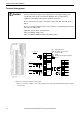
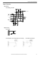
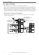
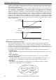
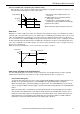
Terminal Arrangement
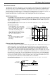
Caution • Connect an IEC 60127-approved fuse appropriate for the applied voltage and
current draw, at the position shown in the diagram. (This is required when
equipment containing the MicroSmart is destined for Europe.)
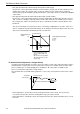
• Do not connect a thermocouple to hazardous voltage (60V DC, 42.4V DC peak or
higher).
• Be sure to check the wiring before the power is turned on. Faulty wiring may result in
damage to the PID module.
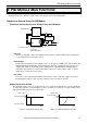
• Applicable electric cables are listed below.
Cable size AWG16: Single-cable
Cable size AWG18, AWG22: Single-cable/Twisted cable
*1: OUT0 is a connection example of relay output.
OUT1 is a connection example of non-contact voltage/current output. The PID module having both outputs
is non-existent.
+
-
NC
+
NC
-
+
-
NC
-
NC -
NC -
NC -
NC -
L
L
+
-
FG
NC
B
-
+
-
TC
A
B
B
RTD
+
-
+
-
+
-
+
-
TC
A
B
B
RTD
+
-
+
-
+
-
-
-
NC
NC
+
”
+
’
+
-
NC
-
B
’
A
B
+
”
+
’
+
-B
’
A
DC DC DC
DC DC DC
24V DC
IN0
IN1
OUT1
OUT0
Channel
Terminal
No.
Terminal
No.
Channel
L
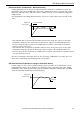
0 to 5V
4 to 20mA
1 to 5V
0 to 10V
0 to 20mA
0 to 1V
0 to 5V
4 to 20mA
1 to 5V
0 to 10V
0 to 20mA
0 to 1V
Fuse (50V-1.2A)
*1
*1
DC : Voltage/Current
RTD : Resistance thermometer
TC : Thermocouple
: Load
: Analog current input instrument
: Fuse