
User manual
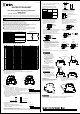

5.Installing the socket
Put the groove on the socket(part B) on the
DIN rail, and press the socket towards the
DIN rail as shown in the figure.
6.Removing the Socket
Insert a small flat screwdriver into the slot (part C)
of the socket, and pull out the socket as shown
in the figure.
$
Type No. RV8H-L-ڧ, RV8H-S-ڧ
1.Terminal Arrangement
2.Wiring Instructions
2-1 RV8H-L-ڧ
Read this instruction sheet to make sure of correct operation before starting installation,wiring, operation,
maintenance, and inspection of this product. Also make sure that this instruction sheet is kept by end users.
Turn off power to the sockets before starting installation, removal, wiring, maintenance, and inspection of
the sockets. Failure to turn power off may cause electrical shocks or fire hazard.
Use proper wires to meet the voltage and current requirements.
Make sure that relay and output equipment are connected completely.
Incomplete connection may cause overheat, resulting in fire hazard.
To ensure safety, make sure that all descriptions in the operation instructions are followed strictly.
Prevent metal fragments and pieces of wire from dropping inside the sockets.
Ingress of such fragments and chips may cause fire, failure, or malfunction.
Use a 15A non-time delay fuse for protection against short-circuit.
When lightening surge may enter the input circuit of types AD12, AD18, and AD24, and when
lightening surge and noise may enter the input circuit of types AD48 and AD60 of the following
products, use a proper varistor. Otherwise, failure maybe caused.
Corresponding products Recommend varistor Example of circuit
RV8H-L-AD12ųųųų
RV8H-L-AD18
RV8H-L-AD24ųų ųų
RV8H-L-AD48ųųųų
RV8H-L-AD60
RV8H-S-AD12ųųųų
RV8H-S-AD18
RV8H-S-AD24ųų ųų
RV8H-S-AD48ųųųų
RV8H-S-AD60
Apply voltage that is applicable to the relay and socket.
Otherwise fire, failure, or malfunction will be caused.
INSTRUCTION SHEET
Slim Relay & Socket Operating Instructions
RV8H Series
Safety Precautions
Use the following applicable wires for wiring.
2.5m੍ max. or AWG14 max., CU(copper), Stranded or Solid wire : 1
1.5m੍ max. or AWG16 max., CU(copper), Stranded wire : 2 max.
ȭ1.3
mm
max. or AWG16 max.
, CU(copper)
solid wire : 2 max.
3.Removing the Relay
Open the release lever in the direction of the arrow, and remove the relay.
Strip the wire insulation 7 to 8 mm from the end.
Stripping the wire insulation too short may cause the wire to come off. Stripping the wire insulation too long
may cause short-circuit with the adjacent socket. Make sure to twist the stranded wire to prevent loosening.
Strip the wire insulation 8 to 9 mm from the end.
Stripping the wire insulation too short may cause the wire to come off. Stripping the wire insulation too long
may cause short-circuit with the adjacent socket. Make sure to twist the stranded wire to prevent loosening.
In applications using ferrules for stranded
wires, choose the ferrule listed in the table.
Recommended tightening torque : 0.3 N
࣭mWR0.4
N
࣭m (UL certificated: 0.35N࣭m)
For wiring, use the following applicable screwdriver.
Phillips screwdriver
3.5mm max.
Flat screwdriver
The relay may pop out
when opening the release
lever, resulting in possible
damage or loss of the relay.
To prevent this, rightly press
down the relay using a
finger when opening the
release lever.
Do not open the release
lever more than 90㺽,
otherwise the socket will
be damaged.
When using wire with insulation diameter or
ȭ2.0mm or less, do not insert the wire too
deep where the insulation inserts into the
spring clamp opening.
Otherwise conductive failure will be caused.
Make sure that the wire insulation is
stripped 8 to 9 mm and the wire is inserted
to the bottom.
4.Installing the Relay
Open the release lever, and insert
the relay into the socket until the
bottom of relay touches the projection
A on the socket. Close the release
lever until it is latched.
When using the RV8H in cold temperature (
0Υ or below),
install or remove the socket
on the mounting rail carefully so that the socket will not be
damaged.
When installing the relay, do
not press in using a relay.
Make sure to use the release
lever, otherwise the projection
A will be damaged.
Release lever
Relay
90㺽
Projection A
Installed securely
5.Installing the
part B
part C
Varistor
Fuse
㹐
http://www.idec.com
2013.4
2-2 RV8H-S-ڧ
Use the following applicable wires for wiring.
0.5m੍ to 2.5m੍ or AWG20 to AWG14, CU(copper),
Stranded or Solid wire : 1
7 to 8mm
8 to 9mm
Applicable
wire(stranded)
m੍
AI0.5-8WH
AI0.75-8GY
AI1-8RD
TE0.5-8
TE0.75-8
TE1.0-8
AWG
0.5
Phoenix
Contact
Nichifu
20
18
18
22
20
18
0.75
1
1
0.5
0.75
Part No.
Manufacturer
For wiring, use the optional screwdriver(BC1S-SD0)
or the following applicable screwdriver.
Wire insertion positions, screwdriver
insertion positions, and the directions
of screwdriver tip are shown below.
Wire Port
Screwdriver Port
Direction of Screwdriver Tip
࣭
࣭
Wiring Instructions
1. Insert the optional screwdriver (BC1S-SD0)
or an applicable screwdriver into the
square-shaped port as shown,until the
screwdriver tip touches the bottom of
the spring.
3. While the screwdriver is retained in the port, insert
the wire of ferrule into the round-shaped wire port.
Each wire port can accommodate one wire or
ferrule. When connecting two wires to one
terminal, use the adjoining port of the same terminal.
4. Pull out the screwdriver. The connection
is now complete.
2. Push in the screwdriver until it touches the
bottom of the port. The wire port is now open,
and the screwdriver is held in place.
The screwdriver will not come off even if you
release your hand.
࣭
Wire Port Bottom
Incorrect Correct
c᳸c
ȭ
3.5mm max.
0.6mm max.
ȭ3.5mm max
ųųᲫ
Ჽ᳃᳆
ųųᲬ
Ჽ᳃᳆
ᲢᲥᲣ
Ჽ᳇
Წ
Ჽ
AC/DC Type
ᲫᲢᲥᲣ
Ჽ᳃᳆
ᲬᲢᲧᲣ
Ჽ᳃᳆
ᲢᲥᲣ
Ჽ᳇
Წ
Ჽ
DC Type
circuit
circuit
Observe the maximum ambient temperature shown below.
Otherwise, fire, failure, or malfunction will be caused.
55Υ maximum: RV8H-L-AD110, RV8H-L-AD220, RV8H-S-AD110, RV8H-S-AD220
70Υ maximum: All other part nos.
Relay & Socket P/N
RV8H-L-D6
RV8H-L-D9
RV8H-L-D12
RV8H-L-D18
RV8H-L-D24
RV8H-L-AD12
RV8H-L-AD18
RV8H-L-AD24
RV8H-L-AD48
RV8H-L-AD60
RV8H-L-AD110
RV8H-L-AD220
Coil Voltage
DC6V
DC9V
DC12V
DC18V
DC24V
AC/DC12V
AC/DC18V
AC/DC24V
AC/DC48V
AC/DC60V
AC/DC110-125V
AC/DC220-240V
Socket P/N
SV1H-07L-5
SV1H-07L-5
SV1H-07L-5
SV1H-07L-5
SV1H-07L-5
SV1H-07L-1
SV1H-07L-1
SV1H-07L-1
SV1H-07L-2
SV1H-07L-2
SV1H-07L-3
SV1H-07L-4
Relay P/N
RV1H-G-D5
RV1H-G-D9
RV1H-G-D12
RV1H-G-D18
RV1H-G-D24
RV1H-G-D12
RV1H-G-D18
RV1H-G-D24
RV1H-G-D48
RV1H-G-D60
RV1H-G-D60
RV1H-G-D60
RV8H-S-D6
RV8H-S-D9
RV8H-S-D12
RV8H-S-D18
RV8H-S-D24
RV8H-S-AD12
RV8H-S-AD18
RV8H-S-AD24
RV8H-S-AD48
RV8H-S-AD60
RV8H-S-AD110
RV8H-S-AD220
DC6V
DC9V
DC12V
DC18V
DC24V
AC/DC12V
AC/DC18V
AC/DC24V
AC/DC48V
AC/DC60V
AC/DC110-125V
AC/DC220-240V
SV1H-07LS-5
SV1H-07LS-5
SV1H-07LS-5
SV1H-07LS-5
SV1H-07LS-5
SV1H-07LS-1
SV1H-07LS-1
SV1H-07LS-1
SV1H-07LS-2
SV1H-07LS-2
SV1H-07LS-3
SV1H-07LS-4
RV1H-G-D5
RV1H-G-D9
RV1H-G-D12
RV1H-G-D18
RV1H-G-D24
RV1H-G-D12
RV1H-G-D18
RV1H-G-D24
RV1H-G-D48
RV1H-G-D60
RV1H-G-D60
RV1H-G-D60
Screw TypeSpring clamp Type
Panasonic ERZV07D390
Panasonic ERZV14D121
Panasonic ERZV07D390
Panasonic ERZV14D121
࣭
ۑ