
User manual
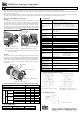

XW1E Series Emergency Stop Switch
Please confirm that the delivered product is what you have ordered.
Safety Precautions
xRead this instruction sheet and the catalog for the XW1E series emergency stop switches to make sure of correct operation before starting
installation, wiring, operation, maintenance, and inspection. Make sure that the instruction sheet is kept by the end user.
x Turn off the power to the XW1E before starting installation, wiring, maintenance and inspection of the XW1E. Failure to turn power off may cause
electric shock or fire hazard.
x Use wires of an appropriate size to meet the voltage and current requirement. Using inappropriate wires may cause overheat, resulting in possible
fire hazard. Also provide necessary protection against electric shock, otherwise electric shock or fire hazard may be caused.
1. Removing and Installing the Contact Block
Removing
For easy removal of the contact block from the operator, first unlock
the operator button. Push back the yellow bayonet ring with force
until the latch pin clicks, then turn the contact block counterclockwise
and pull out. Another method is to insert a small screwdriver into the
latch hole to pull out the latch pin. While pulling the latch outward
lightly, push back the yellow bayonet ring, then turn the contact block
counterclockwise and pull out. D
D
o not pull out the latch strongly.
Excessive force will break the latch.
Note: When the contact block is removed, the monitor contact (NO
contact) is closed.
Installing
For easy installation of the contact block onto the operator, first unlock
the operator button. Align the small ʈ marking on the edge of the
operator boss with the small ʆ marking on the bayonet ring. Hold the
contact block, not the yellow bayonet ring. Press the contact block onto
the operator and turn the contact block clockwise until the bayonet
ring clicks.
2. Contact Ratings [Main Contact (NC) and Monitor Contact (NO)]
Rated Insulation Voltage (Ui)
300V
Rated Current (Ith) 5A
Rated Operating Voltage (Ue) 30V 125V 250V
Resistive Load (AC-12)
5A 3A
AC
50/60Hz
Inductive Load (AC-15)
3A 1.5A
Resistive Load (DC-12) 2A 0.4A 0.2A
Main
Contact
DC
Inductive Load (DC-13) 1A 0.22A 0.1A
Resistive Load (AC-12)
1.2A 0.6A
AC
50/60Hz
Inductive Load (AC-14)
0.6A 0.3A
Resistive Load (DC-12) 2A 0.4A 0.2A
Rated Operating Current
Monitor
Contact
DC
Inductive Load (DC-13) 1A 0.22A 0.1A
3. Internal LED Ratings
Rated Voltage Operating Voltage Operating Current
24V AC/DC 24V AC/DC r10% 15 mA
4. Specifications
Applicable Standard
IEC6094751, EN6094751
IEC6094755, EN6094755
JIS C820151, UL508, CSA C22.2 No. 14
Standard Operating
Conditions
Operating temperature
Nonilluminated: 25 to 60 qC (no freezing)
LED illuminated: 25 to 55 qC (no freezing)
Relative humidity: 45 to 85 % RH (no condensation)
Storage temperature: 45 to 80 qC (no freezing)
Operating Force
Push: 32 N
Turn: 0.27 N㨯m
Pull: 21 N
Minimum Direct
Opening Force
80 N
Minimum Direct
Opening Travel
4.0 mm
Maximum Travel 4.5 mm
Contact Resistance 50 m: maximum (initial value)
Insulation Resistance 100 M: minimum (500V DC megger)
Overvoltage Category II
Impulse Withstand
Voltage
2.5 kV
Pollution Degree 3
Operating Frequency
900 operations/hour
Mechanical Life 250,000 operations minimum
Electrical Life 100,000 operations minimum
Shock Resistance
Operating extremes: 100 m/s
2
Damage limits: 1,000 m/s
2
Vibration Resistance
Operating extremes: 5 to 55 Hz, amplitude 0.5 mm,
acceleration 60 m/s
2
Damage limits: 5 to 55 Hz, amplitude 0.5 mm,
acceleration 60 m/s
2
Degree of Protection IP65 (panel front)
Short-circuit
Protective Device
250V/10A fuse (Type aM IEC602691/IEC602692)
Conditional Short
-circuit Current
1,000 A
Terminal
Configuration
Solder terminal
PC board terminal
Recommended
Tightening Torque of
Locking Ring
2.0 N㨯m
Applicable Wire 1.25 mm
2
maximum (AWG16 maximum)
Soldering Condition 20 W/5 seconds or 260 qC/3 seconds
5. Contact Arrangements (Bottom View)
<Contact configuration with <Contact configuration with
a monitor contact (NO)> main contacts (NC) only>
1NC: Terminals on the top 1NC: Terminals on the right
2NC: Terminals on the right and left 2NC: Terminals on the right and left
3NC: Terminals on the right, left and top
6. Mounting Hole Layout
All dimensions in mm.
www.idec.com No. B
791(1) 2003.8
ٕ marking
ً marking
TOP marking
Ԙ
(Push)
ԙ
(Turn clockwise)
Hold the contact block
1
2
1
2
2
1
2
1
LED
X1
X2
RightLeft
TOP
Right
TOP
1
2
2
1
1
2
3
X1 X2
LED
Left
4
!
ٌ
Bayonet Ring
Latch Hole
ԙ
(Pull)
Ԛ
(Turn counterclockwise)
Ԙ
(Pull out)
ԙ
(Pull)
Ԙ
(Pull out)
Ԛ
(Turn counterclockwise)
ޛWhen mounted on a panelޜޛWhen not mounted on a panelޜ