
User Manual


43. ANTLED 1
44. ANTLED 2
45. Reserve 3
46. 30V LED
47. 12V LED
48. 5V LED
49. Master Reset#
50. RSSI LED
51. Vcc
52. N.C.
53. N.C.
54. N.C.
55. N.C.
56. N.C.
57. N.C.
58. AD5
59. Beep 2
60. Beep 1
61. AD6
62. AD4
63. AD3
64. AD2
65. AD1
66. AD0
67. GND
68. GND
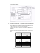
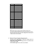
Figure 2
Most of these pins are being used for i-PORT operation. For
operation in regular PCMCIA slots, the user does not have to worry
about the above pinout table, since the configuration is done by the I-
CARD’s firmware for PCMCIA.
4 External Power Supply Requirements
Operation of the i-CARD requires a 5VDC power supply, which is an
integral part of the PCMCIA slot.
Some slots may only provide 3.3V supply and are not suitable for this
revision of the I-CARD.
The maximum supply current will not exceed 150mA.