i-PORT III Installation Manual IDENTEC SOLUTIONS, Inc. Suite 102, 1860 Dayton Street Kelowna, British Columbia Canada V1Y 7W6 Tel: (250) 860-6567 Fax: (250) 860-6541 www.identecsolutions.
Disclaimer and Limitation of Liability IDENTEC SOLUTIONS, Inc. and its affiliates, subsidiaries, officers, directors, employees and agents provide the information contained in this Manual on an “as-is” basis and do not make any express or implied warranties or representations with respect to such information including, without limitation, warranties as to noninfringement, reliability, fitness for a particular purpose, usefulness, completeness, accuracy or currentness. IDENTEC SOLUTIONS, Inc.
Radio Frequency Compliance Statement IDENTEC SOLUTIONS, Inc. is the responsible party for the compliance of the following devices: MODEL: FCC ID: i-PORT III O2E-ILR-916IP3 i-CARD O2E-ICARD-NA i-D2 TAGS OO4-ILR-ID2 CANADA: Pending 35381032231 3538A12112 i-Qxx TAGS OO4-ILR-IQ8T or OO4-ILR-IQR 35381021756A or 35381021825 The user(s) of these products are cautioned to only use accessories and peripherals approved, in advance, by IDENTEC SOLUTIONS, Inc.
Table of Contents 1.0 1.1 1.2 2.0 INTRODUCTION........................................................................................................................................ 5 FUNDAMENTALS ......................................................................................................................................... 5 SYSTEM OVERVIEW ....................................................................................................................................
1.0 1.1 Introduction Fundamentals IDENTEC SOLUTIONS’ ILR® (Intelligent Long Range®) technology is the next generation of long range RFID (Radio Frequency Identification). The objective is wireless and automated data collection over large distances. HOW RFID WORKS Data is transmitted via high frequency radio waves between a tag and an interrogator. Information stored on the tag can be read and modified.
2.0 2.1 INSTALLATION AND START-UP Installation and Start-Up Before installation, the installer shall have a thorough knowledge of the application. The read locations need to be defined; whether the object is moving or stationary needs to be determined. If the objects in question are moving objects, their speed is important for determining the scan interval. The read locations need to be sufficiently spaced.
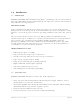
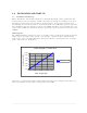
Range (%) Cable Length vs. Range 100 90 80 70 60 50 40 30 20 10 0 0.00 Range c 5.00 10.00 15.00 20.00 Cable Length (m) In the diagram above, the relative range is displayed as a function of the cable length. Relative, because the range is dependent on the environment of the system. Under ideal conditions (free field, high-sensitivity tags, high-sensitivity i-PORT, maximum output power), ranges of up to 100 meters can be achieved.
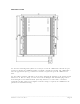
Mounting the i-PORT Use the four mounting holes (diameter 5 mm) to attach the i-PORT. The amount of space required to mount the i-PORT is 200mm x 250mm x 60mm (L x H x W). The i-PORT has a mass of approximately 2 kg. A 3mm hex wrench is required to open the i-PORT access door. Use the rubber grommet with hole to feed cables through the housing to the outside (cable diameter 4.75 mm to 6 mm); seal the unused feed-throughs with the blind plugs.
After mounting the i-PORT, the antennas need to be installed and connected to the appropriate antenna connectors. Alignment of Antennas: Align the antennas with the tags or the objects to be monitored. Linearly polarized antennas must have the same polarization as the tags, either horizontal or vertical. Circular polarized antennas are not dependent on the polarization of the tags. Based on the Orientation Diagram, an initial estimate of the read zone is possible. First set the send range of the i-PORT.
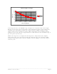
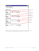
No. Tags in List Tag-ID Field Strength Antenna 1 Field Strength Antenna 2 Session Setup (inactive) Read data (inactive) Data (inactive) The result of the scan is displayed on the debug port. Each Tag-ID is listed with the measured signal strength (depending on the number of active antennas).
LED Displays Status LEDs: a) POWER: Lights when power is applied to the i-PORT b) RUN: Blinks (every 2 seconds) as soon as the i-PORT has booted (approx.
Cable Connections and Plug Allocation Antenna connectors: ANT1-4: SMA sockets, send and receive antennas ANT W: SMA socket, send antenna ONLY (WakeUp Antenna, for i-Q tags only) Terminal Block 1: +10-30V Connection for power supply (10-30V DC) GND Connection for power supply (GND) Terminal Block 2: Functionality has not been implemented at this time. Terminal Block 3: Functionality has not been implemented at this time. Terminal Block 4: Functionality has not been implemented at this time.
3.0 3.1 Software, Configuration Standard Settings, IP-Address, Password The i-PORT is supplied with the following factory settings: IP-Address 192.168.2.244 Subnet-Mask: 255.255.255.0 User Name: user Password: identec To change the IP-Address, see “Boot Menu (Serial)” 3.2 Configuration, Settings Direct Connection: Connect the i-PORT directly to the network connection in your PC, laptop, etc. using a crossover network cable. Ensure that the PC’s IP-Address lies in the same subnet as that of the i-PORT.
“Home” Menu: Information about version numbers, firmware, serial numbers, etc. is contained in this menu. In the top line you can see an overview of all the menus. Click here to get to any of the other menus.
“Status” Menu: Status information, which may be required in case maintenance is needed, is available in this menu. “Processor Activity” Menu: Processor information, which may be required in case maintenance is needed, is available in this menu.
“Testing” Menu: Several test possibilities are available in this menu. i-PORT operation is put on hold during test mode (operation will resume after leaving test mode). The settings from the Configuration Page (antenna settings, slots, etc.) apply here also. Miscellaneous Settings: Tag Type: i-Q8/32 Ant: Send antenna during test mode (for receive antenna, see Configuration) Loop: Operation takes place in closed-loop action Pressing the SCAN button triggers a scan.
“Graphics” Menu: With this menu you have the ability to graphically display a tag’s field strength. This can be useful for estimating the possible ranges i.e. to set the read zones. The parameters from the Configuration Page (antennas, output power, scan-interval, etc.) are to be used as settings. Pressing the DO SCAN button triggers a scan. If tags are located in the zone, a list of these tags will be displayed. Clicking on one or more tags transfers those Tag IDs to the next field.
“Configuration” Menu: _________________________________________________________________________ Page 18 Document #7201-002, Rev C
i-PORT Configuration: Standard i-PORT settings such as type, external devices, etc. i-PORT Type “Fix”, “mobile VisuMC”, and “Client” Enter the i-PORT type. “Fix” runs the I-PORT in host mode (external device must connect to the I-PORT). “Client” runs the I-PORT in client mode (I-PORT connects to external device). “MobileVisuMC” is a special mode for mobile applications and will normally not be used. i-PORT Main ID i-PORT identifier for event messages (Area ID).
Mode: Slot Select Num of Scans Scan Pause 3 possibilities: “Host Only”, “Continuous” and “Input 1” “Host Only” means that the i-PORT waits for commands, processes them, and is otherwise inactive. “Continuous” means that the i-PORT performs continuous scans. “Input 1” mode not available at this time. Number of slots in which tags can answer. This is part of the anti-collision process. Set at least double the amount of slots as the maximum number of tags that can be expected in the zone at one time.
consideration if there are likely to be tags stored for long periods in or near the read zone! Event message: Settings to determine when an event message is to be sent and what the message will contain: Event reason A tag or an input can serve as a trigger for an event Tag 3 possibilities: “Enter”, “Leave” or “Enter or Leave” A message is generated when the tag enters the zone, when it leaves the zone, or both when it enters AND when it leaves the zone.
Sequence: A sequence is defined as successive scans on one or several antennas. Example: 2 antennas are connected (enabled and scan enabled) “Scan” command is sent to the i-PORT Scan is executed on Antenna 1 (Tx), Antennas 1 and 2 receive (Rx) Scan is executed on Antenna 2 (Tx), Antennas 1 and 2 receive (Rx) Results of the scan command / sequence are sent back Calculation examples for “Cable Loss” field: Coaxial cable RG58 has a loss of approximately 0.6dB/m (at 900 MHz).
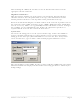
“General” Menu: With this menu, you can change the network settings of the i-PORT. Simply enter the new values in the appropriate fields and click on the SET&REBOOT button. The i-PORT will then reboot with the new network settings. You can write down the new IP address in the designated spot inside the i-PORT door.
3.3 Boot Menu (Serial) It is possible to change basic settings such as IP address, passwords, etc. via the serial interface. To accomplish this, the i-PORT has to be connected via the serial interface to a PC, (with a null-modem serial cable). Next, you need to start a terminal program (Hyperterminal, GanTerm, etc.) with the following settings: Bits per second: Data bits: Parity: Stop bits: Protocol: 9600 8 None 1 None Start up the i-PORT as soon as there is a connection.
You now have the ability to change various standard settings: Project and Location Info: Password Settings: Network Interface Parameters: Hardware Parameters: Location Project Password Enable/Disable Username and Password DHCP/IP Address Subnet Mask Gateway Com1 PPP IP Com1 PPP Peer IP Baud Rate Boot Delay Assignment of i-PORT, Mounting Location Assignment of i-PORT, Project Password on/off Username/Password DHCP or fixed IP Subnet mask Gateway, if needed Necessary for GSM-Modem Necessary for GSM-Modem D
3.4 Interfaces Ethernet Interface: Rate of transmission: 10 / 100 Mbit/s Protocols: TCP/IP, FTP, Telnet, HTTP, SNMP Ports: Debugport Communication Port 7090 7070 for Debug data for communication (commands, messages) WLAN: It is possible to effect a WLAN connection by means of a converter, for example a Client Bridge or Access Point. 3.5 Protocols The protocol used by the i-PORT is an ASCII protocol. The protocol allows a host computer to take control of the process or of the i-PORT.
4.0 4.1 Troubleshooting Troubleshooting 1) If the red Error LED blinks during the boot process and continues blinking after a restart, contact the IDENTEC SOLUTIONS hotline. 2) If the Error LED lights up during operation, a system error has occurred (exception). First execute a cold start (interrupt the power supply) and observe the system. If the error occurs again, contact the IDENTEC SOLUTIONS hotline. 3) For other problems, follow the procedures as outlined below.
ANT4, W) (see “Configuration”) Antenna is defective - Do visual check to see if antenna is defective Change antenna(s) if necessary Tag is out of read zone - Hold a test tag in front of the antenna and check if tag is being recognized (blinks, i.e. Debug port) If necessary, adjust the output power to the requirements Tag is too close to - Move the tag away from the antenna (Note: can antenna manifest if using high power setting and high sensitivity tag setting) Tags are stationary - Move the tags.
5.0 Appendix A - Effective Radiated Power Calculation The following is the licensed limit allowable by the appropriate regulatory bodies for operation of IDENTEC’s RFID devices: i-Q Operation In North America, the approved frequency is 916.5 MHz. Our equipment is certified to transmit an Effective Radiated Power (ERP) of 50mV/m @ 3m. This equates to transmitting 0.75mW from the antenna, or –1.25 dBm.