i-PORT F310 Hardware and Installation Manual
Hardware and Installation Manual Proprietary Notice This document contains confidential information proprietary to IDENTEC SOLUTIONS and may not be used or disclosed to other parties in whole or in part without prior written authorization from IDENTEC SOLUTIONS.
i-PORT F310 Radio Frequency Compliance Statement IDENTEC SOLUTIONS is the responsible party for the compliance of the following devices: MODEL: EUROPE: i-PORT F310 CE The user(s) of these products are cautioned to only use accessories and peripherals approved, in advance, by IDENTEC SOLUTIONS.
Hardware and Installation Manual FCC Registration Required for Operation under Rule 15.240 Radio transmissions from the i-Port F310 are governed in the US by FCC Part 15 rules, and in Canada by corresponding Industry Canada regulation RSS-210 . Still other regulations apply in Europe and other countries. The i-Port F310 is shipped with the default mode of operation corresponding to FCC 15.231. All other Identec Solutions equipment complies with 15.231.
i-PORT F310 Page 5 of 17
Hardware and Installation Manual This product contains components that are sensitive to electrostatic discharges. Please observe the special instructions for their protection. Incorrect handling can damage the unit and cause the invalidation of the warranty. Minimum safety precautions against electrostatic discharge: • Establish earth contact before you touch the unit. For example, touch the earthing screw on the unit.
i-PORT F310 Contents 1 INTRODUCTION ........................................................................................................... 8 1.1 2 ASSOCIATED DOCUMENTS................................................................................................. 8 MECHANICAL INSTALLATION ...................................................................................... 9 2.1 3 DIMENSIONAL DRAWINGS ..............................................................................................
Hardware and Installation Manual 1 Introduction 1.1 Associated Documents Manuals IM.0780.EN IM.0781.EN IM.0782.EN IM.0783.EN System Description, English i-PORT F310 Hardware and Installation Manual, English (this document) Tag Manual (Mounting, Use, and Maintenance), English Symbol Handheld Accessory—Portable Interrogator Data Sheets ID.0680.EN ID.0681.EN ID.0682.EN ID.0683.EN ID.0684.EN ID.0685.EN ID.0686.EN ID.0689.
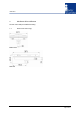
i-PORT F310 2 Mechanical Installation The unit comes with pre-installed mounting 2.
Hardware and Installation Manual 3 Electrical Installation 3.1 Safety Instructions • The power supply circuit must comply with the requirements of the SELV circuits (see EN 60950). • The signal circuits must comply with the requirements of the SELV circuits (see EN 60950). Glossary SELV Safety Extra Low Voltage – Protective measure against dangerous body currents. Protective first voltage, circuit not floating. EMC Electromagnetic Compatibility RxD Receive Data TxD Transmit Data 3.
i-PORT F310 3.3 Power Supply The i-PORT F310 can be powered parallel in two ways: • Mains voltage applied to the connector labeled “AC SUPPLY, 47 … 63 Hz, 90 … 260 VAC” • DC voltage of 10 to 30 VDC applied to the bus connector labeled “RS 485, DC SUPPLY IN, 10 … 30 VDC”. So it is easy to have the mains supply as standard plus a backup battery for uninterrupted operation during power failures. Necessary decoupling circuitry is built-in.
Hardware and Installation Manual Page 12 of 17
i-PORT F310 4 Initial Operation 4.1 Checking the Installation After completing the installation the operation must be systematically checked. The installation check can be divided into three sections: • Visual test • Basic operational check • Detailed operational check If the basic check of the operational behavior is to be carried out using a (portable) PC a final check via the intended user control system should also be carried out. 4.2 Configuration 4.2.1 4.
Hardware and Installation Manual 4.4 Status Display (LEDs) ANT lights green when transmitting RF to a tag, lights orange when receiving data from a tag RUN Device is running properly (LED blinks at approx 1 Hz).
i-PORT F310 5 Maintenance 5.1 General In principle, the ILR system is maintenance-free. When correctly installed it operates for many years without any problems. 5.2 Precautionary Maintenance Regular checking of all ports and cables belonging to the system is recommended. Unstable connections could lead to damage and malfunctions of the system and therefore should be repaired as soon as possible.
Hardware and Installation Manual 5.3 5.3.1 Spare Parts Recommended spare parts stock In order to keep the down time of the system during malfunctions as short as possible it is recommended to have certain spare parts in stock. At least one central unit, one antenna and one antenna cable should be available. With larger systems with more than approx. 15 i-PORTs the doubling of the recommended stock quantity should be considered.
i-PORT F310 6 Technical Data Compatibility ILR® i-Q310 ISO 18000-7 Tags Performance Write range Read range Read rate identification Up to 100 m (300 ft) Up to 100 m (300 ft) 100 tags/s Communication Frequency Certification Data rate up/download Number of antennas Antenna connection Transmit power Transmission safeguard Sensitivity (digitally adjustable) 433.92 MHz ISO/IEC 18000-7 27.