
User's Manual Part 2


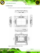


Table Of Contents
- 2 Unpacking
- 3 Installation
- 3.1 Anti-static Precautions
- 3.2 Installation Precautions
- 3.3 Preinstalled Components
- 3.4 CF Card Installation
- 3.5 Mounting the System
- 3.6 Bottom Panel Connectors
- 3.6.1 External Peripheral Device Connection
- 3.6.2 ACC Mode Selection
- 3.6.3 AT/ATX Power Mode Selection
- 3.6.4 Audio Connectors
- 3.6.5 CAN-bus Terminal Block
- 3.6.6 LAN Connector
- 3.6.7 Power Input 1, 3-pin Terminal Block
- 3.6.8 Power Input 2, DIN Connector
- 3.6.9 RJ-45 RS-232 Serial Port
- 3.6.10 RS-422/485 Serial Port
- 3.6.11 USB Connectors
- 3.6.12 VGA Connector
- 3.7 Redundant Power
- 3.8 Remote Control

UPC-V312-D525 Panel PC
Page 10
1.4.6 Frame (Function Keys)
An aluminum frame surrounds the TFT LCD screen. The aluminum frame of the
UPC-V312-D525 contains several function keys that control audio volume, LCD
brightness and some other system components.
Figure 1-8: Function Key Locations
The following table describes the function of these function keys.
Buttons Function Buttons Function
Function
LCD on/off
Enable/Disable RFID
Audio volume down
Mute audio
Audio volume up
Enable/Disable
webcam
Brightness up
Enable/Disable
right side USB port
Brightness down
Power on/off
(Turn on: press 3 seconds
Turn off: press 6 seconds)
Table 1-3: Function Keys
Click to buy NOW!
P
D
F
-
X
C
h
a
n
g
e
V
i
e
w
e
r
w
w
w
.
d
o
c
u
-
t
r
a
c
k
.
c
o
m
Click to buy NOW!
P
D
F
-
X
C
h
a
n
g
e
V
i
e
w
e
r
w
w
w
.
d
o
c
u
-
t
r
a
c
k
.
c
o
m