
User's Manual Part 2


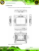


Table Of Contents
- 2 Unpacking
- 3 Installation
- 3.1 Anti-static Precautions
- 3.2 Installation Precautions
- 3.3 Preinstalled Components
- 3.4 CF Card Installation
- 3.5 Mounting the System
- 3.6 Bottom Panel Connectors
- 3.6.1 External Peripheral Device Connection
- 3.6.2 ACC Mode Selection
- 3.6.3 AT/ATX Power Mode Selection
- 3.6.4 Audio Connectors
- 3.6.5 CAN-bus Terminal Block
- 3.6.6 LAN Connector
- 3.6.7 Power Input 1, 3-pin Terminal Block
- 3.6.8 Power Input 2, DIN Connector
- 3.6.9 RJ-45 RS-232 Serial Port
- 3.6.10 RS-422/485 Serial Port
- 3.6.11 USB Connectors
- 3.6.12 VGA Connector
- 3.7 Redundant Power
- 3.8 Remote Control

UPC-V312-D525 Panel PC
Page 13
Optional GPS receiver
Optional 3.75G HSUPA USB module
Audio
2 x Audio speakers
1 x Digital microphone
1 x Line-out connector
1 x Mic-in connector
Expansion
1 x PCIe Mini interface (installed with wireless LAN 802.11
a/b/g/n module)
1 x PCIe Mini slots for mSATA (optional)
Construction Material
Aluminum die-casting (front panel)
Extruded aluminum alloy (chassis)
Mounting
Wall, Stand, Arm (VESA 100 mm x 100 mm and 75 mm x
75 mm with M8 screws)
Front Panel Color
Orange and black
Dimensions (W x H x D) (mm)
338.5 x 276.25 x 62.86
Weight (Net/Gross)
4.5kg/5.0kg
Operating Temperature
-20ºC ~ 50ºC
Storage Temperature
-35ºC ~ 85ºC
Relative Humidity
5%~90%, non-condensing
IP level (full system)
IP 65
Touch Screen
5-wire resistive type
Vibration
MIL-STD-810F 514.5C-2 (with CF card or SSD)
Shock
Half-sine wave shock 3G; 11ms; 3 shocks per axis
65 W
Power Adapter
Input: 100 VAC ~ 240 VAC @ 50 Hz / 60 Hz
Click to buy NOW!
P
D
F
-
X
C
h
a
n
g
e
V
i
e
w
e
r
w
w
w
.
d
o
c
u
-
t
r
a
c
k
.
c
o
m
Click to buy NOW!
P
D
F
-
X
C
h
a
n
g
e
V
i
e
w
e
r
w
w
w
.
d
o
c
u
-
t
r
a
c
k
.
c
o
m