
Manual
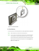
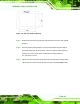
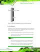
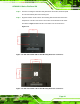
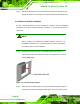
Table Of Contents
- AFOLUX LX Series Flat Panel PC
- 1 Introduction
- 2 Motherboard
- 3 Installation
- 4 System Maintenance
- 5 Award BIOS Setup
- A Safety Precautions
- B BIOS Configuration Options
- C Software Drivers
- D Watchdog Timer
- E Hazardous Materials Disclosure
- F Index
AFOLUX LX Series Flat Panel PC
Page 41
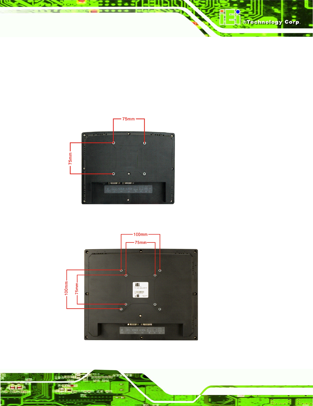
Step 2: Once the mounting arm has been firmly attached to the surface, lift the flat panel
PC onto the interface pad of the mounting arm.
Step 3: Align the retention screw holes on the mounting arm interface with those in the
flat panel PC. The AFL-07A-LX/ AFL-07A-LX arm mount retention screw holes
are shown in
Figure 3-18 and the AFL-10A-LX/AFL-12A-LX are shown in
Figure 3-19.
Figure 3-18: AFL-07A-LX/AFL-08A-LX Arm Mounting Retention Screw Holes
Figure 3-19: AFL-10A-LX/AFL-12A-LX Arm Mounting Retention Screw Holes