AFL-08B-N270 User Manual IEI Technology Corp. MODEL: AFL-08B-N270 Panel PC with Touch Screen, Intel® Atom N270 1.6 GHz CPU, Gigabit Ethernet, Wireless LAN, USB 2.0 External SATA, RS-232/422/485, Audio, RoHS Compliant, IP 64 Protection User Manual Page i Rev. 2.
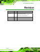
AFL-08B-N270 User Manual Revision Date Version Changes 22 February, 2012 2.20 Bluetooth function optional 12 July, 2011 2.10 Updated WLAN card to RT3090. Added note to Section 2.9 Driver Installation. Added Section A.1.3 Product Disposal. 29 September, 2009 1.02 Added screw torque warning 22 July, 2009 1.01 Minor edit 12 June, 2009 1.
AFL-08B-N270 User Manual Copyright COPYRIGHT NOTICE The information in this document is subject to change without prior notice in order to improve reliability, design and function and does not represent a commitment on the part of the manufacturer. In no event will the manufacturer be liable for direct, indirect, special, incidental, or consequential damages arising out of the use or inability to use the product or documentation, even if advised of the possibility of such damages.
AFL-08B-N270 User Manual Table of Contents 1 INTRODUCTION.........................................................................................................11 1.1 AFL-08B-N270 PANEL PC OVERVIEW .................................................................... 12 1.1.1 Features ........................................................................................................... 13 1.2 EXTERNAL OVERVIEW ...........................................................................................
AFL-08B-N270 User Manual 2.6.4 Arm Mounting .................................................................................................. 43 2.7 BOTTOM PANEL CONNECTORS ................................................................................. 44 2.7.1 LAN Connection............................................................................................... 44 2.7.2 Serial Device Connection and RS-422/485 Pinouts ........................................ 45 2.7.2.
AFL-08B-N270 User Manual 4.3.8 USB Configuration........................................................................................... 81 4.4 PCI/PNP................................................................................................................... 82 4.5 BOOT........................................................................................................................ 85 4.5.1 Boot Settings Configuration..........................................................................
AFL-08B-N270 User Manual List of Figures Figure 1-1: AFL-08B-N270 Panel PC ...........................................................................................12 Figure 1-2: AFL-08B-N270 Front View ........................................................................................14 Figure 1-3: AFL-08B-N270 Rear View .........................................................................................15 Figure 1-4: AFL-08B-N270 I/O Interface Connector Panel..................................
AFL-08B-N270 User Manual Figure 3-4:AFL-08B-N270 SO-DIMM Socket Location...............................................................53 Figure 3-5: DDR2 SO-DIMM Module Installation........................................................................
AFL-08B-N270 User Manual List of Tables Table 1-1: AFL-08B-N270 Specifications....................................................................................18 Table 2-1: Jumpers .......................................................................................................................30 Table 2-2: Preconfigured Jumpers .............................................................................................30 Table 2-3: Clear CMOS Jumper Settings.......................................
AFL-08B-N270 User Manual BIOS Menus BIOS Menu 1: Main .......................................................................................................................59 BIOS Menu 2: Advanced ..............................................................................................................61 BIOS Menu 3: CPU Configuration ...............................................................................................61 BIOS Menu 4: IDE Configuration.........................................
AFL-08B-N270 User Manual Chapter 1 1 Introduction Page 11
AFL-08B-N270 User Manual 1.1 AFL-08B-N270 Panel PC Overview Figure 1-1: AFL-08B-N270 Panel PC The AFOLUX AFL-08B-N270 is an Intel® Atom N270 powered all-in-one touch screen panel PC with a rich variety of functions and peripheral connections. It is designed for easy and simplified integration into conference center, home automation, and building control applications.
AFL-08B-N270 User Manual 1.1.1 Features The AFL-08B-N270 features the following: Intel® Atom™ processor Intel® 945GSE chipset 1 GB 533 MHz DDR2 SDRAM preinstalled 802.11 b/g/n wireless module Two USB 2.0 ports One external SATA port Watchdog timer that triggers a system reset if the system hangs for some reason IP 64 compliant front panel AT or ATX power mode Touch screen RoHS compliance 1.
AFL-08B-N270 User Manual Figure 1-2: AFL-08B-N270 Front View 1.2.2 Rear Panel The rear panel provides access to the internal components of the AFL-08B-N270 and CF card slot. Refer to Figure 1-3 for back cover retention screw and VESA mount screw holes.
AFL-08B-N270 User Manual Figure 1-3: AFL-08B-N270 Rear View 1.2.3 I/O Interface Panel The I/O interface panel located on the bottom of the AFL-08B-N270 has the following I/O interface connectors: 1 x 12 V DC-IN connector 1 x Audio line-out jack 1 x external SATA port 1 x Power switch 1 x Reset button 2 x RJ-45 GbE LAN ports 1 x RS-232 serial port 1 x RS-232/422/485 serial port 2 x USB 2.
AFL-08B-N270 User Manual Figure 1-4: AFL-08B-N270 I/O Interface Connector Panel 1.3 Internal Overview The AFL-08B-N270 has the following components installed internally: 1 x Motherboard 1 x 1.0 GB 533 MHz DDR2 SDRAM SO-DIMM 1 x Wireless LAN module 2 x 1.
AFL-08B-N270 User Manual 1.4 System Specifications The technical specifications for the AFL-08B-N270 systems are listed below. Specifications AFL-08B-N270 LCD Size 8" Max Resolution 800 x 600 Brightness (cd/m2) 300 Contrast Ratio 400:1 LCD Color 262K Pixel Pitch (mm) 0.0675(H) x 0.2025(V) Viewing Angle (H-V) 130º/120º Backlight MTBF 30000 hrs SBC Model AFLMB-945GSE-R10 CPU Intel® Atom™ N270 1.
AFL-08B-N270 User Manual Specifications AFL-08B-N270 Bluetooth V2.0 Optional Construction Material ABS + PC Plastic front frame LED Function One Power ON/OFF LED on Front Panel Mounting Panel, Wall, Rack, Arm, Stand (VESA 75mm x 75mm) Front Panel Color Grey 7539U Dimension (W x H x D mm) 234 x 184 x 42 Operation Temperature (ºC) -10ºC~50ºC Storage Temperature (ºC) -20ºC~60ºC Net Weight 0.
AFL-08B-N270 User Manual Figure 1-6: AFL-08B-N270 Dimensions (mm) Page 19
AFL-08B-N270 User Manual Chapter 2 2 Installation Page 20
AFL-08B-N270 User Manual WARNING: When installing the AFL-08B-N270, make sure to: Turn the power off: Chance of electrocution. Turn off the monitor and unplug it from the power supply. Only let certified engineers change the hardware settings: Incorrect settings can cause irreparable damage to the product. Install the monitor with assistance: The product is very heavy and may be damaged by drops and bumps. Two or more people should install the panel PC.
AFL-08B-N270 User Manual 2.1 Unpack the Panel PC To unpack the panel PC, follow the steps below: WARNING! Only remove the protective plastic cover stuck to the front screen after installation. The plastic layer protects the monitor surface during installation process. Step 1: Carefully cut the tape sealing the box. Only cut deep enough to break the tape. Step 2: Open the outside box. Step 3: Carefully cut the tape sealing the box. Only cut deep enough to break the tape. Step 4: Open the inside box.
AFL-08B-N270 User Manual 1 Power cord P/N: 32000-000002-RS 1 Screw kit (4 x M3; 5mm) P/N: 44013-030041-RS 1 User manual CD and driver CD 1 Touch pen P/N: XTR104-0002-RS Optional WIN CE 6.
AFL-08B-N270 User Manual VSTAND: (P/N: VSTAND-A10) Stand (P/N:STAND-A08) Stand (P/N:STAND-100-RS) Stand (P/N: STAND-150-RS) Arm (P/N: ARM-11-RS) Arm (P/N: ARM-31-RS) Page 24
AFL-08B-N270 User Manual Hybrid card reader (P/N: AFLP-08AMSI-U) Magnetic stripe reader (P/N: AFLP-08AMSR-U) 60 W DC/DC 9-30 VDC input vehicle power adapter: IDD-930160-KIT DC 12 V Input UPS AUPS-A10-R10 DC 9-36V Input UPS AUPS-A20-R10 Make sure all the components listed in the packing list are present. If any of these items are missing or damaged, contact the distributor or sales representative immediately. 2.
AFL-08B-N270 User Manual Figure 2-1: Back Cover Retention Screws Step 2: Lift the cover and pull down the cover a bit to make it possible to fully remove it. More strength is required to separate the cover from the chassis. Step 0: WARNING: Failing to reinstall the covers may result in permanent damage to the system. Please make sure all coverings are properly installed. WARNING: Over-tightening rear cover screws will crack the plastic frame. Maximum torque for cover screws is 5 kg-cm (0.36 lb-ft/0.
AFL-08B-N270 User Manual Step 1: Locate the CF slot cover. Remove the retention screw and CF slot cover (Figure 2-2). Figure 2-2: CF card slot location Step 2: Insert a CF card into the slot (Figure 2-3). Figure 2-3: CF Card Location Step 3: Replace the CF card slot cover. Step 4: Reinsert retention screw.
AFL-08B-N270 User Manual 2.4 AT/ATX Mode Selection AT and ATX power modes can both be used on the AFL-08B-N270. The selection is made through an AT/ATX switch on the top edge of the inner aluminum cover (Figure 2-4). To select AT mode or ATX mode, follow the steps below. Step 1: Locate the AT/ATX switch on the top edge of the aluminum cover (Figure 2-4). Figure 2-4: AT/ATX Switch Location Step 2: Adjust the AT/ATX switch. Step 0: 2.4.
AFL-08B-N270 User Manual 2.4.2 ATX Power Mode With the ATX mode selected, the AFL-08B-N270 panel PC goes in a standby mode when it is turned off. The panel PC can be easily turned on via network or a power switch in standby mode. Remote power control is perfect for advertising applications since the broadcasting time for each panel PC can be set individually and controlled remotely. Other possible application includes Security surveillance Point-of-Sale (POS) Advertising terminal 2.
AFL-08B-N270 User Manual Description Label Type Clear CMOS J_COMS1 2-pin header COM1 Pin 9 setting JP8 10-pin header COM3 Pin 9 setting JP10 6-pin header COM3 RX RS-232/422/485 select JP9 8-pin header COM3 TX RS-422/485 select JP11 6-pin header COM3 RS-232/422/485 select JP6 12-pin header Table 2-1: Jumpers 2.5.1 Access the Jumpers To access the jumpers, remove the back cover and aluminum inner cover. To remove the back panel, please refer to Section 2.2. 2.5.
AFL-08B-N270 User Manual 2.5.3 Clear CMOS Jumper Jumper Label: J_CMOS1 Jumper Type: 2-pin header Jumper Settings: See Table 2-3 Jumper Location: See Figure 2-5 If the AFL-08B-N270 fails to boot due to improper BIOS settings, the clear CMOS jumper clears the CMOS data and resets the system BIOS information. To do this, use the jumper cap to close the pins for a few seconds then remove the jumper clip.
AFL-08B-N270 User Manual Figure 2-5: Clear CMOS Jumper 2.5.4 COM Port Pin 9 Select Jumper Label: JP8 and JP10 Jumper Settings: See Table 2-4 Jumper Location: See Figure 2-6 Two jumpers (JP8 and JP10) configure pin 9 on COM1 and COM3 DB-9 connectors. Pin 9 on the COM1 and the COM3 DB-9 connectors can be set as the ring (RI) signal, +5 V or +12 V. The COM1 and COM3 Pin 9 Setting jumper selection options are shown in Table 2-4.
AFL-08B-N270 User Manual JP10 Description Short 1-2 COM3 RI Pin use +12 V Short 3-4 COM3 RI Pin use RI Short 5-6 COM3 RI Pin use +5 V Default Table 2-5: COM3 Pin 9 Setting Jumper Settings The COM1 and COM3 Pin 9 Setting jumper locations are shown in Figure 2-6 below. Figure 2-6: COM1 and COM3 Pin 9 Setting Jumper Locations 2.5.
AFL-08B-N270 User Manual COM3 RX Function Select Description Short 3-4 RS-232 Short 1-2, 5-6 RS-422 Short 1-2, 7-8 RS-485 Default Table 2-6: COM3 RX Function Select Jumper Settings The COM3 RX Function Select jumper location is shown in Figure 2-7. Figure 2-7: COM3 RX Function Select Jumper Location 2.5.
AFL-08B-N270 User Manual COM3 TX Function Select Description Short 1 – 3 RS-422 Default Short 2 – 4 RS-422 Default Short 3 – 5 RS-485 Short 4 – 6 RS-485 Table 2-7: COM3 TX Function Select Jumper Settings The COM3 TX Function Select jumper location is shown in Figure 2-8 below. Figure 2-8: COM3 TX Function Select Jumper Pinout Locations 2.5.
AFL-08B-N270 User Manual RS-232/485 Select Description Short 1-2 RS-232 Default Short 4-5 RS-232 Default Short 7-8 RS-232 Default Short 10-11 RS-232 Default Short 2-3 RS-422/485 Short 5-6 RS-422/485 Short 8-9 RS-422/485 Short 11-12 RS-422/485 Table 2-8: COM3 RS-232/422/485 Serial Port Select Jumper Settings The COM3 RS-232/422/485 Serial Port Select jumper location is shown in Figure 2-9. Figure 2-9: COM3 RS-232/422/485 Serial Port Select Jumper Location 2.
AFL-08B-N270 User Manual When mounting the panel PC onto an arm, onto the wall or onto a panel, it is better to have more than one person to help with the installation to make sure the panel PC does not fall down and get damaged. The four methods of mounting the AFL-08B-N270 are listed below. Wall mounting Panel mounting Arm mounting Rack mounting The four mounting methods are described below. 2.6.1 Wall Mounting To mount the panel PC onto the wall, please follow the steps below.
AFL-08B-N270 User Manual Figure 2-10: Wall-mounting Bracket Step 6: Insert the four monitor mounting screws provided in the wall mounting kit into the four screw holes on the real panel of the panel PC and tighten until the screw shank is secured against the rear panel (Figure 2-11). Step 7: Align the mounting screws on the monitor rear panel with the mounting holes on the bracket.
AFL-08B-N270 User Manual Figure 2-11: Chassis Support Screws Step 9: Secure the panel PC by fastening the retention screw of the wall-mounting bracket. (Figure 2-12).
AFL-08B-N270 User Manual 2.6.2 Panel Mounting To mount the AFL-08B-N270 panel PC into a panel, please follow the steps below. Step 1: Select the position on the panel to mount the panel PC. Step 2: Cut out a section from the panel that corresponds to the rear panel dimensions of the panel PC. Take care that the panel section that is cut out is smaller than the overall size of the metal frame that surrounds the panel PC but just large enough for the rear panel of the panel PC to fit through (Figure 2-13).
AFL-08B-N270 User Manual Figure 2-14: Tighten the Panel Mounting Clamp Screws 2.6.3 Cabinet and Rack Installation The AFL-08B-N270 panel PC can be installed into a cabinet or rack. The installation procedures are similar to the panel mounting installation. To do this, please follow the steps below: NOTE: When purchasing the cabinet/rack installation bracket, make sure it is compatible with both the AFL-08B-N270 panel PC and the rack/cabinet into which the AFL-08B-N270 is installed.
AFL-08B-N270 User Manual Figure 2-15: The Rack/Cabinet Bracket Step 2: Insert the rack mounting clamps into the pre-formed holes along the edges of the panel PC, behind the ABS/PC plastic frame. Step 3: Tighten the screws that pass through the rack mounting clamps until the plastic caps at the front of all the screws are firmly secured to the bracket (Figure 2-16).
AFL-08B-N270 User Manual Figure 2-17: Install into a Rack/Cabinet Step 5: Once the panel PC with the attached rack/cabinet bracket has been properly inserted into the rack or cabinet, secure the front of the rack/cabinet bracket to the front of the rack or cabinet (Figure 2-17). 2.6.4 Arm Mounting The AFL-08B-N270 is VESA (Video Electronics Standards Association) compliant and can be mounted on an arm with a 75mm interface pad. To mount the panel PC on an arm, please follow the steps below.
AFL-08B-N270 User Manual Step 2: Once the mounting arm has been firmly attached to the surface, lift the panel PC onto the interface pad of the mounting arm. Step 3: Align the retention screw holes on the mounting arm interface with those in the panel PC. The arm mount retention screw holes are shown in Figure 2-18.
AFL-08B-N270 User Manual Step 1: Locate the RJ-45 connector on the bottom panel of the AFL-08B-N270 Series. Step 2: Align the connector. Align the RJ-45 connector on the LAN cable with one of the RJ-45 connectors on the bottom panel of the AFL-08B-N270. See Figure 2-19. Figure 2-19: LAN Connection Step 3: Insert the LAN cable RJ-45 connector. Once aligned, gently insert the LAN cable RJ-45 connector into the onboard RJ-45 connector. Step 0: 2.7.
AFL-08B-N270 User Manual Figure 2-20: Serial Device Connector Step 3: Secure the connector. Secure the serial device connector to the external interface by tightening the two retention screws on either side of the connector. Step 0: 2.7.2.1 COM3 RS-422 and RS-485 Pinouts The pinouts for RS-422 and RS-485 operation of external serial port COM3 are detailed below.
AFL-08B-N270 User Manual 2.7.3 USB Device Connection There are four external USB 2.0 connectors. All connectors are perpendicular to the AFL-08B-N270. To connect a USB 2.0 or USB 1.1 device, please follow the instructions below. Step 1: Located the USB connectors. The locations of the USB connectors are shown in Chapter 2. Step 2: Align the connectors. Align the USB device connector with one of the connectors on the bottom panel. See Figure 2-21.
AFL-08B-N270 User Manual Step 1: Connect the power adapter to the panel PC. Step 2: Connect the power cable to the included power adapter. Step 3: Connect the power cable to the power outlet. Step0: 2.9 Driver Installation NOTE: The content of the CD may vary throughout the life cycle of the product and is subject to change without prior notice. Visit the IEI website or contact technical support for the latest updates.
AFL-08B-N270 User Manual Chapter 3 3 System Maintenance Page 49
AFL-08B-N270 User Manual 3.1 System Maintenance Introduction WARNING! Turn off the power before removing the back cover. Risk of electrocution. Severe damage to the product and injury to the body may occur if internal parts are touched while the power is still on. WARNING! Take antistatic precautions when working on the internal components. Some internal components are easily damaged or destroyed by electrostatic discharge. Take antistatic precautions to prevent electrostatic discharge.
AFL-08B-N270 User Manual Figure 3-1: Replaceable Components 3.2 Motherboard Replacement In the case of motherboard failure, please contact an IEI sales representative, reseller or system vendor. The motherboard is accessible after opening the rear cover. 3.3 Cover Removal To access the AFL-08B-N270 internally the back panel must be removed. To remove the back panel, please follow the steps below. Step 1: Follow all anti-static procedures. See Section A.1.2. Step 2: Turn off the power. See Section 3.1.
AFL-08B-N270 User Manual Figure 3-2: Back Cover Retention Screws Step 4: Lift the cover and pull down the cover a bit to make it possible to fully remove it. More strength is required to separate the cover from the chassis. Step 5: Remove the retention screws (Figure 3-3) from the aluminum cover. Figure 3-3: Aluminum Cover Retention Screws Step 6: Lift off the cover.
AFL-08B-N270 User Manual 3.4 Memory Module Replacement The panel PC is preinstalled with a 1 GB DDR2 memory module. If the memory module is fail, follow the instructions below to replace the memory module. Step 1: Remove the aluminum back cover. See Section 3.3 above. Step 2: Locate the DDR2 SO-DIMM on the motherboard (Figure 3-4). Figure 3-4:AFL-08B-N270 SO-DIMM Socket Location Step 3: Remove the DDR memory module by pulling both the spring retainer clips outward from the socket.
AFL-08B-N270 User Manual Figure 3-5: DDR2 SO-DIMM Module Installation 3.5 CF Card Replacement The AFL-08B-N270 has one CF Type II slot. Follow the instructions below to replace the CF card. Step 1: Follow all anti-static procedures. See Section A.1.2. Step 2: Turn off the power. See Section 3.1. Step 3: Follow the instruction listed in Section 2.3 to replace the CF card. Step 0: 3.6 Reinstalling the Covers WARNING: Failing to reinstall the covers may result in permanent damage to the system.
AFL-08B-N270 User Manual When maintenance procedures are complete, please make sure all the covers are replaced, including the following: Aluminum cover CF card slot cover Page 55
AFL-08B-N270 User Manual Chapter 4 4 BIOS Options Page 56
AFL-08B-N270 User Manual 4.1 Introduction A licensed copy of AMI BIOS is preprogrammed into the ROM BIOS. The BIOS setup program allows users to modify the basic system configuration. This chapter describes how to access the BIOS setup program and the configuration options that may be changed. 4.1.1 Starting Setup The AMI BIOS is activated when the computer is turned on. The setup program can be activated in one of two ways. 1. Press the DELETE key as soon as the system is turned on or 2.
AFL-08B-N270 User Manual F1 key General help, only for Status Page Setup Menu and Option Page Setup Menu F2 /F3 key Change color from total 16 colors. F2 to select color forward. F10 key Save all the CMOS changes, only for Main Menu Table 4-1: BIOS Navigation Keys 4.1.3 Getting Help When F1 is pressed a small help window describing the appropriate keys to use and the possible selections for the highlighted item appears. To exit the Help Window press ESC or the F1 key again. 4.1.
AFL-08B-N270 User Manual 4.2 Main The Main BIOS menu (BIOS Menu 1) appears when the BIOS Setup program is entered. 4 The Main menu gives an overview of the basic system information. Main Advanced PCIPNP BIOS SETUP UTILITY Boot Security Chipset System Overview AMIBIOS Version :08.00.15 Build Date :02/26/09 ID: :H442MR10 Processor Genuine Intel® CPU N270 Speed :1600MHz Count :1 Use [ENTER], [TAB] or [SHIFT-TAB] to select a field.
AFL-08B-N270 User Manual The System Overview field also has two user configurable fields: System Time [xx:xx:xx] Use the System Time option to set the system time. Manually enter the hours, minutes and seconds. System Date [xx/xx/xx] Use the System Date option to set the system date. Manually enter the day, month and year. 4.
AFL-08B-N270 User Manual Main Advanced PCIPNP BIOS SETUP UTILITY Boot Security Chipset Advanced Settings WARNING: Setting wrong values in below sections may cause system to malfunction > > > > > > > Exit Configure CPU CPU Configuration IDE Configuration SuperIO Configuration Hardware Health Configuration Power Configuration Remote Access Configuration USB Configuration Select Screen Select Item Enter Go to SubScreen F1 General Help F10 Save and Exit ESC Exit
AFL-08B-N270 User Manual Brand String: Lists the brand name of the CPU being used Frequency: Lists the CPU processing speed FSB Speed: Lists the FSB speed Cache L1: Lists the CPU L1 cache size Cache L2: Lists the CPU L2 cache size 4.3.2 IDE Configuration Use the IDE Configuration menu (BIOS Menu 4) to change and/or set the configuration 4 of the IDE devices installed in the system.
AFL-08B-N270 User Manual Enhanced mode. In this mode, IDE channels and SATA channels are separated. This mode supports up to 6 storage devices. Some legacy OS do not support this mode. Legacy IDE Channels [PATA Pri, SATA Sec] SATA Only SATA Pri, PATA Sec Only the SATA drives are enabled. DEFAULT The IDE drives are enabled on the Primary IDE channel. The SATA drives are enabled on the Secondary IDE channel. The IDE drives are enabled on the primary PATA Only and secondary IDE channels.
AFL-08B-N270 User Manual Main Advanced PCIPNP BIOS SETUP UTILITY Boot Security Chipset Primary IDE Master Device :Not Detected Type [Auto] LBA/Large Mode [Auto] Block (Multi-Sector Transfer) [Auto] PIO Mode [Auto] DMA Mode [Auto] S.M.A.R.T. [Auto] 32Bit Data Transfer [Enabled] Exit Select the type of device connected to the system Enter F1 F10 ESC Select Screen Select Item Go to SubScreen General Help Save and Exit Exit v02.
AFL-08B-N270 User Manual 32Bit Data Transfer: Enables 32-bit data transfer. Type [Auto] Use the Type BIOS option select the type of device the AMIBIOS attempts to boot from after the Power-On Self-Test (POST) is complete. Not Installed BIOS is prevented from searching for an IDE disk drive on the specified channel. Auto DEFAULT The BIOS auto detects the IDE disk drive type attached to the specified channel.
AFL-08B-N270 User Manual Block (Multi Sector Transfer) [Auto] Use the Block (Multi Sector Transfer) to disable or enable BIOS to auto detect if the device supports multi-sector transfers. Disabled BIOS is prevented from using Multi-Sector Transfer on the specified channel. The data to and from the device occurs one sector at a time. Auto DEFAULT BIOS auto detects Multi-Sector Transfer support on the drive on the specified channel.
AFL-08B-N270 User Manual Auto DEFAULT BIOS auto detects the DMA mode. Use this value if the IDE disk drive support cannot be determined. SWDMA0 Single Word DMA mode 0 selected with a maximum data transfer rate of 2.1MBps SWDMA1 Single Word DMA mode 1 selected with a maximum data transfer rate of 4.2MBps SWDMA2 Single Word DMA mode 2 selected with a maximum data transfer rate of 8.3MBps MWDMA0 Multi Word DMA mode 0 selected with a maximum data transfer rate of 4.
AFL-08B-N270 User Manual S.M.A.R.T [Auto] Use the S.M.A.R.T option to auto-detect, disable or enable Self-Monitoring Analysis and Reporting Technology (SMART) on the drive on the specified channel. S.M.A.R.T predicts impending drive failures. The S.M.A.R.T BIOS option enables or disables this function. Auto BIOS auto detects HDD SMART support. DEFAULT Disabled Prevents BIOS from using the HDD SMART feature.
AFL-08B-N270 User Manual Serial Port1 Address [3F8/IRQ4] Use the Serial Port1 Address option to select the Serial Port 1 base address.
AFL-08B-N270 User Manual Serial Port3 IRQ [11] Use the Serial Port3 IRQ option to select the interrupt address for serial port 3. 10 11 Serial port 3 IRQ address is 10 DEFAULT Serial port 3 IRQ address is 11 Serial Port4 Address [2E8] Use the Serial Port4 IRQ option to select the interrupt address for serial port 4.
AFL-08B-N270 User Manual Main Advanced PCIPNP BIOS SETUP UTILITY Boot Security Chipset Hardware Health Configuration CPU FAN Mode Setting [Full On Mode] CPU Temperature :47ºC/116ºF System Temperature :48ºC/118ºF CPU Fan CPU Core +1.05V +3.30V +5.00V +12.0V +1.50V +1.80V 5VSB VBAT Exit Fan configuration mode setting :N/A :1.120 V :1.040 V Select Screen :3.312 V :4.919 V Select Item :12.096 V Enter Go to SubScreen :1.
AFL-08B-N270 User Manual When the CPU FAN Mode Setting option is in the PWM Manual Mode, the following parameters can be set. CPU Fan PWM control CPU Temp. Limit of OFF [000] WARNING: Setting this value too high may cause the fan to stop when the CPU is at a high temperature and therefore cause the system to be damaged. The CPU Temp Limit of OFF option can only be set if the CPU FAN Mode Setting option is set to Automatic Mode. Use the CPU Temp.
AFL-08B-N270 User Manual and enter a decimal number between 000 and 127. The temperature range is specified below. Minimum Value: 0°C Maximum Value: 127°C CPU Fan Start PWM [070] The Fan 3 Start PWM option can only be set if the CPU FAN Mode Setting option is set to Automatic Mode. Use the Fan 3 Start PWM option to select the PWM mode the fan starts to rotate with after the temperature specified in the Temperature 3 Limit of Start is exceeded. The Super I/O chipset supports 128 PWM modes.
AFL-08B-N270 User Manual o o System Temperature Fan Speeds: The CPU cooling fan speed is monitored. o CPU Temperature CPU Fan Speed Voltages: The following system voltages are monitored o o o o o o o o o CPU Core +1.05V +3.30V +5.00V +12.0 V +1.5V +1.8V 5VSB VBAT 4.3.5 Power Configuration The Power Configuration menu (BIOS Menu 8) configures the Advanced Configuration and Power Interface (ACPI) and Power Management (APM) options.
AFL-08B-N270 User Manual 4.3.5.1 ACPI configuration The ACPI Configuration menu (BIOS Menu 9) configures the Advanced Configuration 4 and Power Interface (ACPI). Main Advanced PCIPNP BIOS SETUP UTILITY Boot Security Chipset ACPI Settings Suspend Mode [S1 (POS)] Exit Set the ACPI state used for System suspend Enter F1 F10 ESC Select Screen Select Item Go to SubScreen General Help Save and Exit Exit v02.61 ©Copyright 1985-2006, American Megatrends, Inc.
AFL-08B-N270 User Manual Main Advanced PCIPNP BIOS SETUP UTILITY Boot Security Chipset APM Configuration Restore on AC Power Loss [Power On] Power Button Mode [On/Off] Advanced Resume Resume Resume Resume Resume Events Controls on Keyboard/Mouse On Ring on PCI-Express Wake# on RTC Alarm [Disabled] [Disabled] [Disabled] [Disabled] Exit Go into On/Off, or Suspend when Power button is pressed Enter F1 F10 ESC Select Screen Select Item Go to SubScreen General H
AFL-08B-N270 User Manual Resume on Keyboard/Mouse [Disabled] Use the Resume on Keyboard/Mouse BIOS option to enable activity on either the keyboard or mouse to rouse the system from a suspend or standby state. That is, the system is roused when the mouse is moved or a button on the keyboard is pressed.
AFL-08B-N270 User Manual Resume On RTC Alarm [Disabled] Use the Resume On RTC Alarm option to specify the time the system should be roused from a suspended state. Disabled DEFAULT The real time clock (RTC) cannot generate a wake event If selected, the following appears with values that Enabled can be selected: RTC Alarm Date (Days) System Time After setting the alarm, the computer turns itself on from a suspend state when the alarm goes off. 4.3.
AFL-08B-N270 User Manual Remote Access [Disabled] Use the Remote Access option to enable or disable access to the remote functionalities of the system. Disabled Enabled DEFAULT Remote access is disabled. Remote access configuration options shown below appear: Serial Port Number Serial Port Mode Redirection after BIOS POST Terminal Type These configuration options are discussed below.
AFL-08B-N270 User Manual Serial Port Mode [115200 8,n,1] Use the Serial Port Mode option to select baud rate through which the console redirection is made.
AFL-08B-N270 User Manual 4.3.8 USB Configuration Use the USB Configuration menu (BIOS Menu 12) to read USB configuration 4 information and configure the USB settings. Main Advanced PCIPNP BIOS SETUP UTILITY Boot Security Chipset USB Configuration Module Version – 2.24.3-13.4 Exit Options Disabled Enabled USB Devices Enabled: None USB Function USB 2.0 Controller Legacy USB Support USB 2.
AFL-08B-N270 User Manual Normally if this option is not enabled, any attached USB mouse or USB keyboard does not become available until a USB compatible operating system is fully booted with all USB drivers loaded. When this option is enabled, any attached USB mouse or USB keyboard can control the system even when there is no USB driver loaded onto the system.
AFL-08B-N270 User Manual Main Advanced PCIPNP BIOS SETUP UTILITY Boot Security Chipset Exit Advanced PCI/PnP Settings WARNING: Setting wrong values in below sections may cause system to malfunction IRQ3 [Reserved] IRQ4 [Reserved] IRQ5 [Available] IRQ7 [Available] IRQ9 [Available] IRQ10 [Reserved] IRQ11 [Reserved] IRQ14 [Available] IRQ15 [Available] Available: Specified IRQ is available to be use the PCI/PnP devices Reserved: Specified IRQ is reserved for use by legacy
AFL-08B-N270 User Manual IRQ9 IRQ10 IRQ 11 IRQ 14 IRQ 15 DMA Channel# [Available] Use the DMA Channel# option to assign a specific DMA channel to a particular PCI/PnP device.
AFL-08B-N270 User Manual 4.5 Boot Use the Boot menu (BIOS Menu 14) to configure system boot options. 4 Main Advanced PCIPNP BIOS SETUP UTILITY Boot Security Chipset Boot Settings > Boot Settings Configuration > > > > Boot Device Priority Hard Disk Drives CD/DVD Drives Removable Drives Exit Configure settings during system boot. Enter F1 F10 ESC Select Screen Select Item Go to SubScreen General Help Save and Exit Exit v02.
AFL-08B-N270 User Manual Quick Boot [Enabled] Use the Quick Boot BIOS option to make the computer speed up the boot process. Disabled Enabled No POST procedures are skipped DEFAULT Some POST procedures are skipped to decrease the system boot time Quiet Boot [Disabled] Use the Quiet Boot BIOS option to select the screen display when the system boots.
AFL-08B-N270 User Manual automatically when the computer system boots up. This allows the immediate use of the 10-key numeric keypad located on the right side of the keyboard. To confirm this, the Number Lock LED light on the keyboard is lit. Boot From LAN Support [Disabled] The BOOT From LAN Support option enables the system to be booted from a remote system.
AFL-08B-N270 User Manual 4.6 Security Use the Security menu (BIOS Menu 16) to set system and user passwords. 4 Main Advanced BIOS SETUP UTILITY Boot Security PCIPNP Chipset Exit Security Settings Supervisor Password :Not Installed User Password :Not Installed Change Supervisor Password Change User Password Enter F1 F10 ESC Select Screen Select Item Go to SubScreen General Help Save and Exit Exit v02.61 ©Copyright 1985-2006, American Megatrends, Inc.
AFL-08B-N270 User Manual WARNING! Setting the wrong values for the Chipset BIOS selections in the Chipset BIOS menu may cause the system to malfunction. Main Advanced PCIPNP BIOS SETUP UTILITY Boot Security Chipset Exit Advanced Chipset Settings WARNING: Setting wrong values in below section may cause system to malfunction.
AFL-08B-N270 User Manual Main Advanced PCIPNP BIOS SETUP UTILITY Boot Security Chipset Exit Northbridge Chipset Configuration Memory Hole [Disabled] Internal Graphics Mode Select [Enabled, 8MB] Video Function Configuration DVMT Mode Select [DVMT Mode] DVMT/FIXED Memory [128MB] Select Screen Boot Display Device [LFP] Select Item DVMT/FIXED Memory [CRT] Enter Go to SubScreen LFP Panel Type [by H/W] F1 General Help LFP Current Jumpe
AFL-08B-N270 User Manual DVMT Mode Select [DVMT Mode] Use the DVMT Mode Select option to select the Intel Dynamic Video Memory Technology (DVMT) operating mode. A fixed portion of graphics memory is reserved as Fixed Mode graphics memory. DVMT Mode DEFAULT Graphics memory is dynamically allocated according to the system and graphics needs. A fixed portion of graphics memory is reserved as Combo Mode graphics memory.
AFL-08B-N270 User Manual Sec. Display Device [CRT] Use the Sec. Display Device option to select the second display device used by the system. Configuration options are listed below. Disabled CRT DEFAULT LFP Panel Type [by H/W] Use the LFP Panel Type option to select the type of panel connected to the system. Configuration options are listed below.
AFL-08B-N270 User Manual Main Advanced PCIPNP BIOS SETUP UTILITY Boot Security Chipset Exit Southbridge Chipset Configuration Audio Controller [Auto] Select Screen Select Item Enter Go to SubScreen F1 General Help F10 Save and Exit ESC Exit v02.61 ©Copyright 1985-2006, American Megatrends, Inc. BIOS Menu 19: Southbridge Chipset Configuration Audio Controller [AC’97 Audio Only] The Audio Controller option enables or disables the audio controller.
AFL-08B-N270 User Manual Main Advanced PCIPNP BIOS SETUP UTILITY Boot Security Chipset Exit Options Save Changes and Exit Discard Changes and Exit Discard Changes Load Optimal Defaults Load Failsafe Defaults Exit Exit system setup after saving the changes. F10 key can be used for this operation Enter F1 F10 ESC Select Screen Select Item Go to SubScreen General Help Save and Exit Exit v02.61 ©Copyright 1985-2006, American Megatrends, Inc.
AFL-08B-N270 User Manual Appendix A A Safety Precautions Page 95
AFL-08B-N270 User Manual WARNING: The precautions outlined in this chapter should be strictly followed. Failure to follow these precautions may result in permanent damage to the AFL-08B-N270. A.1 Safety Precautions Please follow the safety precautions outlined in the sections that follow: A.1.1 General Safety Precautions Please ensure the following safety precautions are adhered to at all times. Follow the electrostatic precautions outlined below whenever the AFL-08B-N270 is opened.
AFL-08B-N270 User Manual A.1.2 Anti-static Precautions WARNING: Failure to take ESD precautions during the installation of the AFL-08B-N270 may result in permanent damage to the AFL-08B-N270 and sever injury to the user. Electrostatic discharge (ESD) can cause serious damage to electronic components, including the AFL-08B-N270. Dry climates are especially susceptible to ESD.
AFL-08B-N270 User Manual A.1.3 Product Disposal CAUTION: Risk of explosion if battery is replaced by and incorrect type. Only certified engineers should replace the on-board battery. Dispose of used batteries according to instructions and local regulations. Outside the European Union - If you wish to dispose of used electrical and electronic products outside the European Union, please contact your local authority so as to comply with the correct disposal method.
AFL-08B-N270 User Manual Except for the LCD panel, never spray or squirt liquids directly onto any other components. To clean the LCD panel, gently wipe it with a piece of soft dry cloth or a slightly moistened cloth. The interior does not require cleaning. Keep fluids away from the interior. Be careful not to damage the small, removable components inside. Turn off before cleaning. Never drop any objects or liquids through the openings.
AFL-08B-N270 User Manual Appendix B B BIOS Options Page 100
AFL-08B-N270 User Manual Below is a list of BIOS configuration options in the BIOS chapter. System Overview .................................................................................................................59 System Time [xx:xx:xx] .......................................................................................................60 System Date [xx/xx/xx] ........................................................................................................
AFL-08B-N270 User Manual Resume On RTC Alarm [Disabled].....................................................................................78 RTC Alarm Date (Days)........................................................................................................78 System Time .........................................................................................................................78 Remote Access [Disabled].................................................................................
AFL-08B-N270 User Manual Audio Controller [AC’97 Audio Only].................................................................................93 Save Changes and Exit .......................................................................................................94 Discard Changes and Exit...................................................................................................94 Discard Changes...................................................................................................
AFL-08B-N270 User Manual Appendix C C Terminology Page 104
AFL-08B-N270 User Manual AC ’97 Audio Codec 97 (AC’97) refers to a codec standard developed by Intel® in 1997. ACPI Advanced Configuration and Power Interface (ACPI) is an OS-directed configuration, power management, and thermal management interface. AHCI Advanced Host Controller Interface (AHCI) is a SATA Host controller register-level interface. ATA The Advanced Technology Attachment (ATA) interface connects storage devices including hard disks and CD-ROM drives to a computer.
AFL-08B-N270 User Manual DIMM Dual Inline Memory Modules are a type of RAM that offer a 64-bit data bus and have separate electrical contacts on each side of the module. EHCI The Enhanced Host Controller Interface (EHCI) specification is a register-level interface description for USB 2.0 Host Controllers. EIDE Enhanced IDE (EIDE) is a newer IDE interface standard that has data transfer rates between 4.0 MBps and 16.6 MBps.
AFL-08B-N270 User Manual RAM Random Access Memory (RAM) is volatile memory that loses data when power is lost. RAM has very fast data transfer rates compared to other storage like hard drives. SATA Serial ATA (SATA) is a serial communications bus designed for data transfers between storage devices and the computer chipsets. The SATA bus has transfer speeds up to 1.5 Gbps and the SATA II bus has data transfer speeds of up to 3.0 Gbps. S.M.A.R.T Self Monitoring Analysis and Reporting Technology (S.M.A.R.
AFL-08B-N270 User Manual Appendix D D Watchdog Timer Page 108
AFL-08B-N270 User Manual NOTE: The following discussion applies to DOS environment. IEI support is contacted or the IEI website visited for specific drivers for more sophisticated operating systems, e.g., Windows and Linux. The Watchdog Timer is provided to ensure that standalone systems can always recover from catastrophic conditions that cause the CPU to crash. This condition may have occurred by external EMIs or a software bug.
AFL-08B-N270 User Manual NOTE: When exiting a program it is necessary to disable the Watchdog Timer, otherwise the system resets.
AFL-08B-N270 User Manual Appendix E E Hazardous Materials Disclosure Page 111
AFL-08B-N270 User Manual E.1 Hazardous Materials Disclosure Table for IPB Products Certified as RoHS Compliant Under 2002/95/EC Without Mercury The details provided in this appendix are to ensure that the product is compliant with the Peoples Republic of China (China) RoHS standards. The table below acknowledges the presences of small quantities of certain materials in the product, and is applicable to China RoHS only.
AFL-08B-N270 User Manual Part Name Toxic or Hazardous Substances and Elements Lead Mercury Cadmium Hexavalent Polybrominated Polybrominated (Pb) (Hg) (Cd) Chromium Biphenyls Diphenyl Ethers (CR(VI)) (PBB) (PBDE) Housing X O O O O X Display X O O O O X Printed Circuit X O O O O X Metal Fasteners X O O O O O Cable Assembly X O O O O X Fan Assembly X O O O O X Power Supply X O O O O X O O O O O O Board Assemblies Battery O: This toxic or
AFL-08B-N270 User Manual 此附件旨在确保本产品符合中国 RoHS 标准。以下表格标示此产品中某有毒物质的含量符 合中国 RoHS 标准规定的限量要求。 本产品上会附有”环境友好使用期限”的标签,此期限是估算这些物质”不会有泄漏或突变”的 年限。本产品可能包含有较短的环境友好使用期限的可替换元件,像是电池或灯管,这些元 件将会单独标示出来。 部件名称 有毒有害物质或元素 铅 汞 镉 六价铬 多溴联苯 多溴二苯醚 (Pb) (Hg) (Cd) (CR(VI)) (PBB) (PBDE) 壳体 X O O O O X 显示 X O O O O X 印刷电路板 X O O O O X 金属螺帽 X O O O O O 电缆组装 X O O O O X 风扇组装 X O O O O X 电力供应组装 X O O O O X 电池 O O O O O O O: 表示该有毒有害物质在该部件所有物质材料中的含量均在 SJ/T11363-2006 标准规定的限量要求