
Owner manual

AFOLUX AFL-15A-N270 Panel PC
Page 58
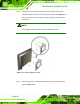
Step 2: Once the mounting arm has been firmly attached to the surface, lift the flat panel
PC onto the interface pad of the mounting arm.
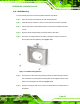
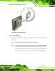
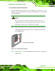
Step 3: Align the retention screw holes on the mounting arm interface with those in the
flat panel PC. The AFL-15A-N270 arm mount retention screw holes are shown in
Figure 4-17.
Figure 4-17: Arm Mounting Retention Screw Holes
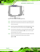
Step 4: Secure the flat panel PC to the interface pad by inserting four retention screws
through the bottom of the mounting arm interface pad and into the flat panel PC.
Step 0: