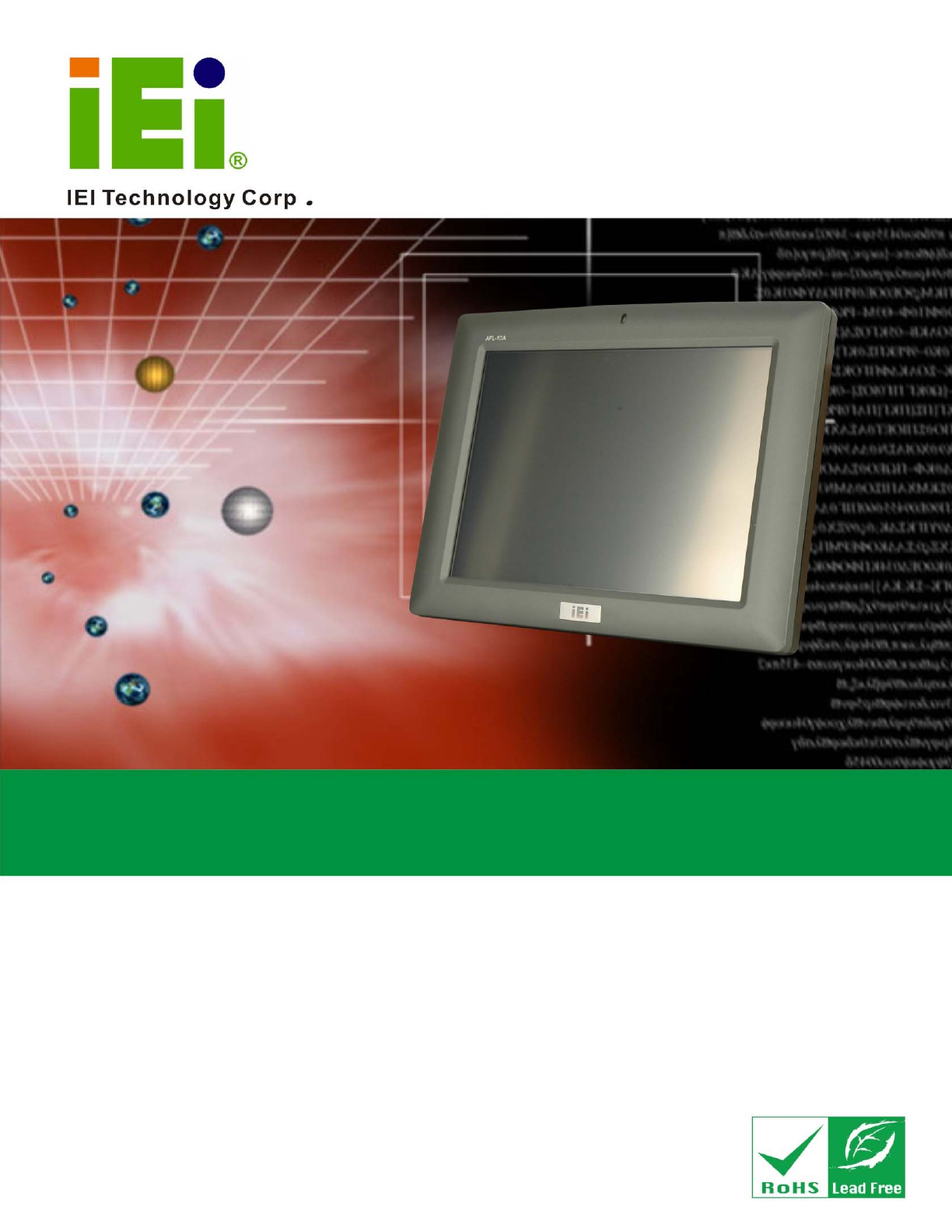
AFL-xxA-N26 Series Panel PC o42AFL-xxA-N26 Series Flat Panel PC MODEL: AFL-xxA-N26 Fanless All-in-one Panel PC with 1.6 GHz Intel® Atom™ Processor TFT LCD, Wireless LAN, Touch Screen, RS-232/422/485 and IP 64 Protection User Manual Page 1 Rev. 1.
AFL-xxA-N26 Series Panel PC Revision Date Version Changes 26 March, 2013 1.01 Updated supported memory frequency 9 November, 2012 1.
AFL-xxA-N26 Series Panel PC Copyright COPYRIGHT NOTICE The information in this document is subject to change without prior notice in order to improve reliability, design and function and does not represent a commitment on the part of the manufacturer. In no event will the manufacturer be liable for direct, indirect, special, incidental, or consequential damages arising out of the use or inability to use the product or documentation, even if advised of the possibility of such damages.
AFL-xxA-N26 Series Panel PC WARNING: This equipment has been tested and found to comply with the limits for a Class A and Class B digital device, pursuant to part 15 of the FCC Rules. These limits are designed to provide reasonable protection against harmful interference in a residential installation. This equipment generates, uses and can radiate radio frequency energy and, if not installed and used in accordance with the instructions, may cause harmful interference to radio communications.
AFL-xxA-N26 Series Panel PC Table of Contents 1 INTRODUCTION........................................................................................................ 15 1.1 OVERVIEW................................................................................................................ 16 1.1.1 Features and Model Variations........................................................................ 16 1.1.2 Applications .....................................................................................
AFL-xxA-N26 Series Panel PC 3.8 JUMPER SETTINGS .................................................................................................... 42 3.8.1 Access the Jumpers .......................................................................................... 43 3.8.2 Preconfigured Jumpers .................................................................................... 43 3.8.3 Clear CMOS Jumper........................................................................................ 44 3.8.
AFL-xxA-N26 Series Panel PC 5.2 MAIN........................................................................................................................ 71 5.3 ADVANCED ............................................................................................................... 72 5.3.1 ACPI Settings ................................................................................................... 73 5.3.2 RTC Wake Settings .............................................................................
AFL-xxA-N26 Series Panel PC 7.2.2 Audio MIC-in Connector (MIC1) .................................................................. 122 7.2.3 Audio DMIC-in Connector (DMIC1)............................................................. 122 7.2.4 Battery Connector (CN1)............................................................................... 123 7.2.5 COM2 Connector (COM2) ............................................................................ 123 7.2.6 CPU Fan Connector (CPU_FAN1)..................
AFL-xxA-N26 Series Panel PC 7.4.2 Inverter ADJ Power Selection Jumper (JP6)................................................. 135 7.4.3 Inverter Power Selection Jumper (JP1)......................................................... 135 7.4.4 LVDS Panel Voltage Selection Jumper (J_VLVDS1) ..................................... 136 7.4.5 Touchscreen Selection Jumper (J1)................................................................ 136 A SAFETY PRECAUTIONS ......................................................
AFL-xxA-N26 Series Panel PC List of Figures Figure 1-1: AFOLUX AFL-xxA-N26 Flat Panel PC......................................................................16 Figure 1-2: AFL-xxA-N26 Front View ..........................................................................................18 Figure 1-3: AFL-xxA-N26 Rear View ...........................................................................................18 Figure 1-4: AFL-10A-N26 I/O Interface Connector Panel ........................................
AFL-xxA-N26 Series Panel PC Figure 3-21: AFL-10A-N26 Panel Opening .................................................................................52 Figure 3-22: AFL-12A-N26 Panel Opening .................................................................................53 Figure 3-23: Tighten the Panel Mounting Clamp Screws .........................................................53 Figure 3-24: AFL-W07A-N26/AFL-08A-N26 Arm Mounting Retention Screw Holes...............
AFL-xxA-N26 Series Panel PC Figure 6-20: Preparing Setup Screen ...................................................................................... 110 Figure 6-21: InstallShield Wizard Welcome Screen ............................................................... 110 Figure 6-22: Audio Driver Software Configuration................................................................. 111 Figure 6-23: Restart the Computer ........................................................................................
AFL-xxA-N26 Series Panel PC List of Tables Table 1-1: Model Variations .........................................................................................................17 Table 1-2: AFL-xxA-N26 Series System Specifications ............................................................26 Table 3-1: Jumpers .......................................................................................................................43 Table 3-2: Preconfigured Jumpers ...........................................
AFL-xxA-N26 Series Panel PC Table 7-22: TTL Panel Connector (CN6) Pinouts.................................................................... 130 Table 7-23: USB Connector (USB1) Pinouts........................................................................... 130 Table 7-24: USB Connector (USB2) Pinouts........................................................................... 130 Table 7-25: USB Connector (USB3) Pinouts...........................................................................
AFL-xxA-N26 Series Panel PC Chapter 1 1 Introduction Page 15
AFL-xxA-N26 Series Panel PC 1.1 Overview Figure 1-1: AFOLUX AFL-xxA-N26 Flat Panel PC The AFL-xxA-N26 series is Intel® Atom™ N2600 powered flat panel PCs with a rich variety of functions and peripherals. All AFL-xxA-N26 models are designed for easy and simplified integration in to kiosk and point-of-sales (POS) applications. The Intel® NM10 Express Chipset ensures optimal memory, graphics, and peripheral I/O support. The system comes with 2.
AFL-xxA-N26 Series Panel PC Two USB 2.0 ports Watchdog timer that triggers a system reset if the system hangs for some reason Supports secondary display through VGA connection 9 V ~ 28 V wide range DC power input mSATA SSD supported IP 64 compliant front panel AT or ATX power mode Touch screen RoHS compliance There are four kinds of panel size of the AFL-xxA-N26 series. The model numbers and model variations are listed below.
AFL-xxA-N26 Series Panel PC provides access to external interface connectors that include LAN, USB 2.0, serial port, reset button, power connector and power switch. 1.2.1 Front Panel The front side of the AFOLUX AFL-xxA-N26 series is a flat panel TFT LCD screen with LED backlight surrounded by an ABS/PC plastic frame. The top of the front panel has a power LED. Figure 1-2: AFL-xxA-N26 Front View 1.2.2 Rear Panel The rear panel provides access to retention screw holes that support VESA mounting.
AFL-xxA-N26 Series Panel PC 1.2.3 I/O Interface Panel The I/O interface panel located on the bottom of the AFL-xxA-N26 has the following I/O interface connectors: 1 x Audio line-out connector 1 x 9 V ~ 28 V DC In connector 1 x RS-232 RJ-45 connector (COM1) 1 x RS-232/422/485 DB-9 connector o o COM3: RS-232 COM4: RS-422/485 2 x GbE RJ-45 connectors 2 x USB 2.0 connectors (W07A, 08A, 10A models) 4 x USB 2.
AFL-xxA-N26 Series Panel PC Figure 1-5: AFL-12A-N26 I/O Interface Connector Panel 1.2.4 Top Panel and Side Panels The top panel and side panels of AFOLUX AFL-xxA-N26 series provide access to slots that support panel mount and rack mount (Figure 1-6).
AFL-xxA-N26 Series Panel PC 1.3 Dimensions The following sections provide detailed schematics and information on the dimensions of the AFL-xxA-N26 series. 1.3.1 AFL-W07A-N26 Dimensions The AFL-W07A-N26 dimensions are shown in Figure 1-8 and listed below. Width: 226.00 mm Height: 140.00 mm Depth: 40.
AFL-xxA-N26 Series Panel PC 1.3.2 AFL-08A-N26 Dimensions The AFL-08A-N26 dimensions are shown in Figure 1-9 and listed below. Width: 233.86 mm Height: 183.89 mm Depth: 41.
AFL-xxA-N26 Series Panel PC 1.3.3 AFL-10A-N26 Dimensions The AFL-10A-N26 dimensions are shown in Figure 1-10 and listed below. Width: 276.0 mm Height: 222.0 mm Depth: 51.
AFL-xxA-N26 Series Panel PC 1.3.4 AFL-12A-N26 Dimensions The AFL-12A-N26 dimensions are shown in Figure 1-10 and listed below. Width: 304.0 mm Height: 246.0 mm Depth: 49.
AFL-xxA-N26 Series Panel PC 1.4 Internal Overview The AFOLUX AFL-xxA-N26 has the following components installed internally: 1 x Motherboard 1 x 2.0 GB 1333 MHz/1066 MHz DDR3 SDRAM SO-DIMM 1 x Wireless module 1.5 System Specifications The technical specifications for the AFOLUX AFL-xxA-N26 series systems are listed in Table 1-2. Specification AFL-W07A-N26 AFL-08A-N26 AFL-10A-N26 AFL-12A-N26 LCD Size Wide 7” 8.4” 10.4” 12.1” Max.
AFL-xxA-N26 Series Panel PC VESA 100 mm x 100 mm (AFL-10A-N26 and AFL-12A-N26 only) Front Panel Color Gray 7539U Dimensions (W x H x D) 226 x 140 x 41 234 x 184 x 42 276 x 222 x 51 304 x 246 x 50 1.4 kg 1.8 kg (mm) Operation Temperature -10ºC ~ 50ºC Storage Temperature -20ºC ~ 60ºC Humidity 10% ~ 95% (non-condensing) Net weight 0.
AFL-xxA-N26 Series Panel PC Chapter 2 2 Unpacking Page 27
AFL-xxA-N26 Series Panel PC 2.1 Unpacking To unpack the flat panel PC, follow the steps below: WARNING! The front side LCD screen has a protective plastic cover stuck to the screen. Only remove the plastic cover after the flat panel PC has been properly installed. This ensures the screen is protected during the installation process. Step 1: Use box cutters, a knife or a sharp pair of scissors that seals the top side of the external (second) box. Step 2: Open the external (second) box.
AFL-xxA-N26 Series Panel PC 2.1.
AFL-xxA-N26 Series Panel PC 1 User manual CD and driver CD Optional Panel mounting kit (P/N: AFLPK-12) Wall mounting kit (P/N: AFLWK-12) Stand (P/N:STAND-A12) Arm (P/N: ARM-11-RS) Arm (P/N: ARM-31-RS) LCD monitor stand with adjustable hinge (P/N: VSTAND-A07/A10/A12) Page 30
AFL-xxA-N26 Series Panel PC Hybrid Card Reader (P/N: AFLP-xxAMSI-U) Magnetic card reader (P/N: AFLP-xxAMSR-U) DC 9~36 V Input UPS (P/N: AUPS-A20-R10) DC 12 V Input UPS (P/N: AUPS-A10-R10) If any of these items are missing or damaged, contact the distributor or sales representative immediately.
AFL-xxA-N26 Series Panel PC Chapter 3 3 Page 32 Installation
AFL-xxA-N26 Series Panel PC 3.1 Anti-static Precautions WARNING: Failure to take ESD precautions during the maintenance of the AFL-xxA-N26 may result in permanent damage to the AFL-xxA-N26 and severe injury to the user. Electrostatic discharge (ESD) can cause serious damage to electronic components, including the AFL-xxA-N26. Dry climates are especially susceptible to ESD.
AFL-xxA-N26 Series Panel PC Anti-static Discharge: If a user open the rear panel of the flat panel PC, to configure the jumpers or plug in added peripheral devices, ground themselves first and wear and anti-static wristband. 3.3 Installation and Configuration Steps The following installation steps must be followed.
AFL-xxA-N26 Series Panel PC Figure 3-1: Back Cover Retention Screws Step 2: Remove the retention screws securing the internal aluminum cover. The screw numbers are varied in different models. The following figures show the aluminum cover retention screws of each model.
AFL-xxA-N26 Series Panel PC Figure 3-4: AFL-10A-N26 Aluminum Back Cover Retention Screws Figure 3-5: AFL-12A-N26 Aluminum Back Cover Retention Screws Step 3: Lift the aluminum cover off the AFL-xxA-N26 series. Step 0: 3.5 mSATA SSD Installation The AFL-xxA-N26 series has one PCIe Mini slot inside the rear panel for mSATA SSD installation. To install the mSATA SSD, follow the instructions below. Step 1: Open the system by following the instruction described in Section 3.4.
AFL-xxA-N26 Series Panel PC Figure 3-6: PCIe Mini Slot Location Step 3: Insert into the socket at an angle. Line up the notch on the card with the notch on the connector. Slide the PCIe Mini card into the socket at an angle of about 20º. Figure 3-7: PCIe Mini Card Installation Step 4: Push down until the card clips into place. Push the other end of the card down until it clips into place on the plastic connector. Step 5: Attach the thermal pad onto the mSATA card.
AFL-xxA-N26 Series Panel PC Figure 3-8: mSATA Card Thermal Pad Step 6: Replace the internal aluminum cover and the plastic back cover. Step 0: WARNING: The mSATA card thermal pad helps draw the heat away from the mSATA components and evenly dissipates it into the heat sink on the internal aluminum cover. Failing to apply the thermal pad properly may cause SSD and system damage.
AFL-xxA-N26 Series Panel PC 3.6 HDD Installation (AF-12A-N26 Only) To install the HDD into the AF-12A-N26, please follow the steps below: Step 1: Open the system by following the instruction described in Section 3.4. Step 2: Remove the four HDD bracket retention screws (Figure 3-9). Disconnect the SATA cable and the SATA power cable. Lift the HDD bracket off the panel PC. Figure 3-9: AF-12A-N26 HDD Bracket Retention Screws Step 3: Attach the HDD brackets to the HDD.
AFL-xxA-N26 Series Panel PC Figure 3-10: AF-12A-N26 HDD Retention Screws Step 4: Install the HDD into the AF-12A-N26 by aligning the retention screw holes in the HDD brackets with the retention screw holes on the chassis. Insert the four retention screws. Step 5: Connect the SATA cable and the SATA power cable to the connectors on the motherboard. Figure 3-11: AF-12A-N26 HDD Installation Step 6: Replace the aluminum back cover to the chassis. Step 7: Replace the plastic back cover.
AFL-xxA-N26 Series Panel PC WARNING: Over-tightening back cover screws will crack the plastic frame. Maximum torque for cover screws is 5 kg-cm (0.36 lb-ft/0.49 Nm). 3.7 AT/ATX Mode Selection AT and ATX power modes can both be used on the AFL-xxA-N26 series. The selection is made through an AT/ATX switch on the bottom panel (Figure 3-12). To select AT mode or ATX mode, follow the steps below. Step 1: Locate the AT/ATX switch on the bottom panel (Figure 3-12).
AFL-xxA-N26 Series Panel PC Manufacturing shop flow 3.7.2 ATX Power Mode With the ATX mode selected, the AFL-xxA-N26 panel PC goes in a standby mode when it is turned off. The panel PC can be easily turned on via network or a power switch in standby mode. Remote power control is perfect for advertising applications since the broadcasting time for each panel PC can be set individually and controlled remotely.
AFL-xxA-N26 Series Panel PC Description Label Type Clear CMOS JP2 3-pin header COM3 Pin 9 setting JP5 6-pin header RS-232/422/485 select JP4 12-pin header Table 3-1: Jumpers 3.8.1 Access the Jumpers To access the jumpers, remove the back cover and the aluminum cover. To remove the covers, please refer to Section 3.4. 3.8.2 Preconfigured Jumpers WARNING: Do not change the settings on the jumpers in described here. Doing so may disable or damage the system.
AFL-xxA-N26 Series Panel PC 3.8.3 Clear CMOS Jumper Jumper Label: JP2 Jumper Type: 3-pin header Jumper Settings: See Table 3-3 Jumper Location: See Figure 3-13 If the AFL-xxA-N26 fails to boot due to improper BIOS settings, the clear CMOS jumper clears the CMOS data and resets the system BIOS information. To do this, use the jumper cap to close the pins for a few seconds then remove the jumper clip.
AFL-xxA-N26 Series Panel PC Figure 3-13: Clear CMOS Jumper 3.8.4 COM3 Port Pin 9 Select Jumper Label: JP5 Jumper Type: 6-pin header Jumper Settings: See Table 3-4 Jumper Location: See Figure 3-14 This jumper configures pin 9 on COM3 DB-9 connector. Pin 9 on the COM3 DB-9 connector can be set as the ring (RI) signal, +5 V or +12 V. The COM3 Pin 9 Setting jumper selection options are shown in Table 3-4.
AFL-xxA-N26 Series Panel PC Figure 3-14: COM3 Pin 9 Setting Jumper Location 3.8.5 RS-232/422/485 Serial Port Select Jumper Jumper Label: JP4 Jumper Type: 12-pin header (four 3-pin headers combined) Jumper Settings: See Table 3-5 Jumper Location: See Figure 3-15 The RS-232/422/485 Serial Port Select jumper sets the communication protocol used by the DB-9 serial communications port as RS-232, RS-422 or RS-485. The RS-232/422/485 Serial Port Select settings are shown in Table 3-5.
AFL-xxA-N26 Series Panel PC Figure 3-15: RS-232/422/485 Serial Port Select Jumper Location 3.8.5.1 COM4 RS-422 and RS-485 Pinouts The pinouts for RS-422 and RS-485 operation of external serial port COM 4 are detailed below.
AFL-xxA-N26 Series Panel PC 3.9 Mounting the System WARNING! When mounting the flat panel PC onto an arm, onto the wall or onto a panel, it is better to have more than one person to help with the installation to make sure the panel PC does not fall down and get damaged. The four methods of mounting the AFOLUX AFL-xxA-N26 are listed below. Wall mounting Panel mounting Arm mounting Rack mounting The four mounting methods are described below. 3.9.
AFL-xxA-N26 Series Panel PC Figure 3-16: Wall-mounting Bracket Step 6: Insert the four monitor mounting screws provided in the wall mount kit into the four screw holes on the real panel of the flat panel PC and tighten until the screw shank is secured against the rear panel (Figure 3-17). WARNING: Please use the M4 screws provided in the wall mount kit for the rear panel. If the screw is missing, the thread depth of the replacement screw should be not more than 4 mm.
AFL-xxA-N26 Series Panel PC Step 7: Align the mounting screws on the monitor rear panel with the mounting holes on the bracket. Step 8: Carefully insert the screws through the holes and gently pull the monitor downwards until the monitor rests securely in the slotted holes (Figure 3-17). Ensure that all four of the mounting screws fit snuggly into their respective slotted holes. NOTE: In the diagram below the bracket is already installed on the wall.
AFL-xxA-N26 Series Panel PC Figure 3-18: Secure the Panel PC 3.9.2 Panel Mounting To mount the AFOLUX AFL-xxA-N26 series flat panel PC into a panel, please follow the steps below. Step 1: Select the position on the panel to mount the flat panel PC. Step 2: Cut out a section from the panel that corresponds to the rear panel dimensions of the flat panel PC.
AFL-xxA-N26 Series Panel PC Figure 3-19: AFL-W07A-N26 Panel Opening Figure 3-20: AFL-08A-N26 Panel Opening Figure 3-21: AFL-10A-N26 Panel Opening Page 52
AFL-xxA-N26 Series Panel PC Figure 3-22: AFL-12A-N26 Panel Opening Step 3: Slide the flat panel PC through the hole until the frame is flush against the panel. Step 4: Insert the panel mounting clamps into the pre-formed holes along the edges of the chassis, behind the frame. Step 5: Tighten the screws that pass through the panel mounting clamps until the plastic caps at the front of all the screws are firmly secured to the panel (Figure 3-23).
AFL-xxA-N26 Series Panel PC 3.9.3 Arm Mounting The AFL-xxA-N26 series is VESA (Video Electronics Standards Association) compliant and can be mounted on an arm with a 75mm interface pad. To mount the AFL-xxA-N26 series on an arm, please follow the steps below. Step 1: The arm is a separately purchased item. Please correctly mount the arm onto the surface it uses as a base. To do this, refer to the installation documentation that came with the mounting arm.
AFL-xxA-N26 Series Panel PC Figure 3-25: AFL-10A-N26/AFL-12A-N26 Arm Mounting Retention Screw Holes Step 4: Secure the flat panel PC to the interface pad by inserting four retention screws through the bottom of the mounting arm interface pad and into the flat panel PC. Step 0: 3.9.4 Cabinet and Rack Installation The AFL-xxA-N26 series flat panel PC can be installed into a cabinet or rack. The installation procedures are similar to the panel mounting installation.
AFL-xxA-N26 Series Panel PC Figure 3-26: The Rack/Cabinet Bracket Step 2: Insert the rack mounting clamps into the pre-formed holes along the edges of the flat panel PC, behind the ABS/PC plastic frame. There are a total of 4 rack mounting clamps for AFL-W07A-N26/AFL-08A-N26 and 6 rack mounting clamps for AFL-10A-N26/AFL-12A-N26. Step 3: Tighten the screws that pass through the rack mounting clamps until the plastic caps at the front of all the screws are firmly secured to the bracket (Figure 3-27).
AFL-xxA-N26 Series Panel PC Figure 3-28: Install into a Rack/Cabinet Step 5: Once the flat panel PC with the attached rack/cabinet bracket has been properly inserted into the rack or cabinet, secure the front of the rack/cabinet bracket to the front of the rack or cabinet (Figure 3-28). 3.10 Bottom Panel Connectors 3.10.1 LAN Connection There are two external RJ-45 LAN connectors. The RJ-45 connector enables connection to an external network.
AFL-xxA-N26 Series Panel PC Figure 3-29: LAN Connection Step 3: Insert the LAN cable RJ-45 connector. Once aligned, gently insert the LAN cable RJ-45 connector into the onboard RJ-45 connector. Step 0: 3.10.2 Serial Device Connection (DB-9) The AFOLUX AFL-xxA-N26 Series has one male DB-9 connector on the bottom panel for serial devices to be connected. Follow the steps below to connect a serial device to the AFOLUX AFL-xxA-N26 Series panel PC. Step 1: Locate the DB-9 connector.
AFL-xxA-N26 Series Panel PC Figure 3-30: Serial Device Connector Step 3: Secure the connector. Secure the serial device connector to the external interface by tightening the two retention screws on either side of the connector.
AFL-xxA-N26 Series Panel PC 3.10.3 RJ-45 to DB-9 Serial Cable Connection The AFL-xxA-N26 has one serial device connector on the bottom panel. The serial device slots (RJ-45) connect to a cable with a standard DB-9 connector at the other end. Follow the steps below to connect a serial device to the AFL-xxA-N26 panel PC. Step 1: Locate the RJ-45 connector. The location of the RJ-45 serial port connector is shown in Chapter 1.
AFL-xxA-N26 Series Panel PC Step 1: Located the USB connectors. The locations of the USB connectors are shown in Chapter 1. Step 2: Align the connectors. Align the USB device connector with one of the connectors on the bottom panel. See Figure 3-32. Figure 3-32: USB Device Connection Step 3: Insert the device connector. Once aligned, gently insert the USB device connector into the onboard connector.
AFL-xxA-N26 Series Panel PC Chapter 4 4 Page 62 System Maintenance
AFL-xxA-N26 Series Panel PC 4.1 System Maintenance Introduction If the components of the AFOLUX AFL-xxA-N26 series fail they must be replaced. Components that can be replaced include: Wireless LAN module SO-DIMM module mSATA SSD module Please contact the system reseller or vendor to purchase the replacement parts. Back cover removal instructions for the AFOLUX AFL-xxA-N26 series are described below. 4.
AFL-xxA-N26 Series Panel PC 4.3 Turn off the Power WARNING: Failing to turn off the system before opening it can cause permanent damage to the system and serious or fatal injury to the user. Before any maintenance procedures are carried out on the system, make sure the system is turned off. 4.4 Opening the System WARNING: Over-tightening back cover screws will crack the plastic frame. Maximum torque for cover screws is 5 kg-cm (0.36 lb-ft/0.49 Nm).
AFL-xxA-N26 Series Panel PC Figure 4-1: AFL-10A-N26 SO-DIMM Socket Location Step 5: Remove the memory module by pulling both the spring retainer clips outward from the socket. Step 6: Grasp the memory module by the edges and carefully pull it out of the socket. Step 7: Install the new memory module by pushing it into the socket at an angle (Figure 4-2). Step 8: Gently pull the spring retainer clips of the SO-DIMM socket out and push the rear of the memory module down (Figure 4-2).
AFL-xxA-N26 Series Panel PC 4.5.2 WLAN Module Replacement The AFOLUX AFL-xxA-N26 series is pre-installed one PCIe Mini wireless module. To replace the wireless module, follow the instructions below. Step 1: Follow all anti-static procedures. See Section 4.2. Step 2: Turn off the power. See Section 4.3. Step 3: Remove the back cover and the internal aluminum back cover. See Section 3.4. Step 4: Locate the WLAN module. Step 5: Disconnect the antennas on the WLAN module (Figure 4-3).
AFL-xxA-N26 Series Panel PC Step 8: Install a new WLAN module by inserting the card into the slot at an angle Step 9: Push the WLAN module down until the spring retainer clips lock into place. Step 10: Connect the two antennas. Step 11: Replace the internal aluminum cover and the back cover. Secure them to the chassis using previously removed retention screws.Step 0: 4.6 Reinstalling the Covers WARNING: Failing to reinstall the covers may result in permanent damage to the system.
AFL-xxA-N26 Series Panel PC Chapter 5 5 AMI BIOS Setup Page 68
AFL-xxA-N26 Series Panel PC 5.1 Introduction A licensed copy of AMI BIOS is preprogrammed into the ROM BIOS. The BIOS setup program allows users to modify the basic system configuration. This chapter describes how to access the BIOS setup program and the configuration options that may be changed. 5.1.1 Starting Setup The AMI BIOS is activated when the computer is turned on. The setup program can be activated in one of two ways. 1. Press the DELETE key as soon as the system is turned on or 2.
AFL-xxA-N26 Series Panel PC F1 key General help, only for Status Page Setup Menu and Option Page Setup Menu F2 key Load previous values F3 key Load optimized defaults F4 key Save changes and Exit BIOS Table 5-1: BIOS Navigation Keys 5.1.3 Getting Help When F1 is pressed a small help window describing the appropriate keys to use and the possible selections for the highlighted item appears. To exit the Help Window press ESC or the F1 key again. 5.1.
AFL-xxA-N26 Series Panel PC 5.2 Main The Main BIOS menu (BIOS Menu 1) appears when the BIOS Setup program is entered. 6 The Main menu gives an overview of the basic system information. Aptio Setup Utility – Copyright (C) 2011 American Megatrends, Inc. Main Advanced Chipset Boot Security Save & Exit BIOS Information BIOS Vendor Core Version Compliency Project Version Build Date and Time American Megatrends 4.6.5.3 0.16 UEFI 2.3; PI 1.2 H714AR12.ROM 10/22/2012 18:31:26 Set the Date.
AFL-xxA-N26 Series Panel PC Î System Time [xx:xx:xx] Use the System Time option to set the system time. Manually enter the hours, minutes and seconds. 5.3 Advanced Use the Advanced menu (BIOS Menu 2) to configure the CPU and peripheral devices 6 through the following sub-menus: WARNING: Setting the wrong values in the sections below may cause the system to malfunction. Make sure that the settings made are compatible with the hardware.
AFL-xxA-N26 Series Panel PC Aptio Setup Utility – Copyright (C) 2011 American Megatrends, Inc. Main Advanced Chipset Boot Security Save & Exit > > > > > > > > > ACPI Settings RTC Wake Settings CPU Configuration IDE Configuration USB Configuration F81866 Super IO Configuration F81866 H/M Monitor Serial Port Console Redirection iEi Feature System ACPI Parameters. ---------------------- ÅÆ: Select Screen ↑ ↓: Select Item Enter Select +/-: Change Opt.
AFL-xxA-N26 Series Panel PC Î ACPI Sleep State [S1 (CPU Stop Clock)] Use the ACPI Sleep State option to specify the sleep state the system enters when it is not being used. Î S1 (CPU Stop DEFAULT The system enters S1 (POS) sleep state. The system appears off. The CPU is stopped; RAM is Clock) refreshed; the system is running in a low power mode. Î S3 (Suspend The caches are flushed and the CPU is powered to off. Power to the RAM is maintained.
AFL-xxA-N26 Series Panel PC Î Wake System with Fixed Time [Disabled] Use the Wake System with Fixed Time option to specify the time the system should be roused from a suspended state.
AFL-xxA-N26 Series Panel PC Aptio Setup Utility – Copyright (C) 2011 American Megatrends, Inc. Advanced CPU Configuration Processor Type EMT64 Processor Speed System Bus Speed Ratio Status Actual Ratio System Bus Speed Processor Stepping Microcode Revision L1 Cache RAM L2 Cache RAM Processor Core Hyper-Threading Intel(R) Atom(TM) CPU N2600 @ 1.
AFL-xxA-N26 Series Panel PC Î Hyper-threading [Enabled] Use the Hyper-threading function to enable or disable the CPU hyper threading function. Î Disabled Î Enabled Disables the use of hyper-threading technology DEFAULT Enables the use of hyper-threading technology 5.3.4 IDE Configuration Use the IDE Configuration menu (BIOS Menu 6) to change and/or set the configuration of the IDE devices installed in the system. Aptio Setup Utility – Copyright (C) 2011 American Megatrends, Inc.
AFL-xxA-N26 Series Panel PC 5.3.5 USB Configuration Use the USB Configuration menu (BIOS Menu 7) to read USB configuration information and configure the USB settings. Aptio Setup Utility – Copyright (C) 2011 American Megatrends, Inc. Advanced USB Configuration USB Devices: 1 Keyboard Legacy USB Support [Enabled] Enables Legacy USB support. AUTO option disables legacy support if no USB devices are connected. DISABLE option will keep USB devices available only for EFI applications.
AFL-xxA-N26 Series Panel PC Î Disabled Legacy USB support disabled Î Auto Legacy USB support disabled if no USB devices are connected 5.3.6 F81866 Super IO Configuration Use the F81866 Super IO Configuration menu (BIOS Menu 8) to set or change the configurations for the serial ports. Aptio Setup Utility – Copyright (C) 2011 American Megatrends, Inc.
AFL-xxA-N26 Series Panel PC 5.3.6.1 Serial Port n Configuration Use the Serial Port n Configuration menu (BIOS Menu 9) to configure the serial port n. Aptio Setup Utility – Copyright (C) 2011 American Megatrends, Inc. Advanced Serial Port 1 Configuration Enable or Disable Serial Port (COM) Serial Port Device Settings [Enabled] IO=3F8h; IRQ=4 --------------------ÅÆ: Select Screen ↑ ↓: Select Item Enter Select +/-: Change Opt.
AFL-xxA-N26 Series Panel PC Î Serial Port I/O port address is 3F8h and the IO=3F8h; IRQ=3, 4 interrupt address is IRQ3, 4 Î Serial Port I/O port address is 2F8h and the IO=2F8h; IRQ=3, 4 interrupt address is IRQ3, 4 Î Serial Port I/O port address is 3E8h and the IO=3E8h; IRQ=3, 4 interrupt address is IRQ3, 4 Î Serial Port I/O port address is 2E8h and the IO=2E8h; IRQ=3, 4 interrupt address is IRQ3, 4 5.3.6.1.
AFL-xxA-N26 Series Panel PC Î Î Î IO=2E8h; Serial Port I/O port address is 2E8h and the IRQ=10,11 interrupt address is IRQ10, 11 IO=250h; Serial Port I/O port address is 250h and the IRQ=10,11 interrupt address is IRQ10, 11 IO=2E0h; Serial Port I/O port address is 2E0h and the IRQ=10,11 interrupt address is IRQ10, 11 5.3.6.1.3 Serial Port 4 Configuration Î Serial Port [Enabled] Use the Serial Port option to enable or disable the serial port.
AFL-xxA-N26 Series Panel PC Î Î IO=250h; Serial Port I/O port address is 250h and the IRQ=10,11 interrupt address is IRQ10, 11 IO=2E0h; Serial Port I/O port address is 2E0h and the IRQ=10,11 interrupt address is IRQ10, 11 5.3.7 F81866 H/W Monitor The F81866 H/W Monitor menu (BIOS Menu 10) shows the operating temperature, fan speeds and system voltages. Aptio Setup Utility – Copyright (C) 2011 American Megatrends, Inc.
AFL-xxA-N26 Series Panel PC Aptio Setup Utility – Copyright (C) 2011 American Megatrends, Inc.
AFL-xxA-N26 Series Panel PC Î Auto Duty-Cycle DEFAULT Duty-Cycle settings Mode Î The fan adjusts its speed using Auto by System Temperature n Use the + or – key to change the System Temperature n value. Enter a decimal number between 1 and 100. 5.3.8 Serial Port Console Redirection The Serial Port Console Redirection menu (BIOS Menu 12) allows the console redirection options to be configured.
AFL-xxA-N26 Series Panel PC 5.4 iEi Feature Use the iEi Feature menu (BIOS Menu 13) to configure the auto recovery function. Aptio Setup Utility – Copyright (C) 2011 American Megatrends, Inc. Advanced iEi Feature Auto Recovery Function [Disabled] Auto Recovery Function Reboot and recover system automatically within 10 min, when OS crashes. Please install Auto Recovery API service before enabling this function --------------------ÅÆ: Select Screen ↑ ↓: Select Item Enter Select +/-: Change Opt.
AFL-xxA-N26 Series Panel PC 5.5 Chipset Use the Chipset menu (BIOS Menu 14) to access the North Bridge, South Bridge, Integrated Graphics, and ME Subsystem configuration menus. WARNING! Setting the wrong values for the Chipset BIOS selections in the Chipset BIOS menu may cause the system to malfunction. Aptio Setup Utility – Copyright (C) 2011 American Megatrends, Inc.
AFL-xxA-N26 Series Panel PC 5.5.1 Host Bridge Configuration Use the Host Bridge menu (BIOS Menu 15) to configure the Host Bridge chipset. Aptio Setup Utility – Copyright (C) 2011 American Megatrends, Inc. Chipset >Intel IGD Configuration ******* Memory Information ******* Memory Frequency 800 MHz(DDR3) Total Memory 2048 MB DIMM#1 2048 MB Select which graphics controller to use as the primary boot device. --------------------ÅÆ: Select Screen ↑ ↓: Select Item Enter Select + - Change Opt.
AFL-xxA-N26 Series Panel PC Î Fixed Graphics Memory Size [128MB] Use the Fixed Graphics Memory Size option to specify the maximum amount of memory that can be allocated as graphics memory. Configuration options are listed below. 128 MB 256 MB DEFAULT 5.5.2 South Bridge Configuration Use the South Bridge menu (BIOS Menu 17) to configure the Southbridge chipset. Aptio Setup Utility – Copyright (C) 2011 American Megatrends, Inc.
AFL-xxA-N26 Series Panel PC Î Power Saving Function [Disabled] Use the Power Saving Function BIOS option to enable or disable the power saving function. Î Disabled Î Enabled DEFAULT Power saving function is disabled. Power saving function is enabled. It will reduce power consumption when the system is off. Î Set Spread Spectrum fucntion [Disabled] Use the Set Spread Spectrum function option to reduce the EMI. Excess EMI is generated when the system clock generator pulses have extreme values.
AFL-xxA-N26 Series Panel PC 5.6 Boot Use the Boot menu (BIOS Menu 18) to configure system boot options. Aptio Setup Utility – Copyright (C) 2011 American Megatrends, Inc. Main Advanced Chipset Boot Security Save & Exit Boot Configuration Bootup NumLock State Quiet Boot Launch PXE OpROM Option ROM Messages UEFI Boot [On] [Enabled] [Disabled] [Force BIOS] [Disabled] Select the keyboard NumLock state --------------------ÅÆ: Select Screen ↑ ↓: Select Item Boot Option Priorities Enter Select +/-: Change Opt.
AFL-xxA-N26 Series Panel PC Î Quiet Boot [Enabled] Use the Quiet Boot BIOS option to select the screen display when the system boots. Î Î Disabled Î Enabled Normal POST messages displayed DEFAULT OEM Logo displayed instead of POST messages Launch PXE OpROM [Disabled] Use the Launch PXE OpROM option to enable or disable boot option for legacy network devices.
AFL-xxA-N26 Series Panel PC 5.7 Security Use the Security menu (BIOS Menu 19) to set system and user passwords. Aptio Setup Utility – Copyright (C) 2011 American Megatrends, Inc. Main Advanced Chipset Boot Security Save & Exit Password Description If ONLY the Administrator’s password is set, then this only limits access to Setup and is only asked for when entering Setup If ONLY the User’s password is set, then this is a power on password and must be entered to boot or enter Setup.
AFL-xxA-N26 Series Panel PC 5.8 Save & Exit Use the Save & Exit menu (BIOS Menu 20) to load default BIOS values, optimal failsafe values and to save configuration changes. Aptio Setup Utility – Copyright (C) 2011 American Megatrends, Inc. Main Advanced Chipset Boot Security Save & Exit Save Changes and Reset Discard Changes and Reset Reset the system after saving the changes.
AFL-xxA-N26 Series Panel PC Î Save as User Defaults Use the Save as User Defaults option to save the changes done so far as user defaults. Î Restore User Defaults Use the Restore User Defaults option to restore the user defaults to all the setup options.
AFL-xxA-N26 Series Panel PC Chapter 6 6 Software Drivers Page 96
AFL-xxA-N26 Series Panel PC 6.1 Available Software Drivers NOTE: The content of the CD may vary throughout the life cycle of the product and is subject to change without prior notice. Visit the IEI website or contact technical support for the latest updates. The following drivers can be installed on the system: Chipset VGA LAN Audio Touch screen Wireless Installation instructions are given below. 6.
AFL-xxA-N26 Series Panel PC Figure 6-1: Drivers 6.3 Chipset Driver Installation To install the chipset driver, please do the following. Step 1: Access the driver list shown in Figure 6-1 (See Section 6.2). Click “Chipset”. Step 2: The setup files are extracted as shown in Figure 6-2.
AFL-xxA-N26 Series Panel PC Figure 6-2: Chipset Driver Screen Step 3: When the setup files are completely extracted the Welcome Screen in Figure 6-3 appears. Figure 6-3: Chipset Driver Welcome Screen Step 4: Click Next to continue. Step 5: The license agreement in Figure 6-4 appears.
AFL-xxA-N26 Series Panel PC Step 6: Read the License Agreement. Step 7: Click the Yes icon to continue. Figure 6-4: Chipset Driver License Agreement Step 8: The Read Me file in Figure 6-5 appears. Step 9: Click Next to continue.
AFL-xxA-N26 Series Panel PC Figure 6-5: Chipset Driver Read Me File Step 10: Setup Operations are performed as shown in Figure 6-6.
AFL-xxA-N26 Series Panel PC Step 11: Once the Setup Operations are complete, click the Next icon to continue. Step 12: The Finish screen appears. Step 13: Select “Yes, I want to restart the computer now” and click the Finish icon. See Figure 6-7. Figure 6-7: Chipset Driver Installation Finish Screen 6.4 VGA Driver Installation To install the VGA driver, please do the following. Step 1: Access the driver list shown in Figure 6-1 (See Section 6.2). Click “VGA”.
AFL-xxA-N26 Series Panel PC Figure 6-8: VGA Driver Read Me File Step 4: The installation files are extracted. See Figure 6-9. Figure 6-9: VGA Driver Setup Files Extracted Step 5: The Welcome Screen in Figure 6-10 appears.
AFL-xxA-N26 Series Panel PC Figure 6-10: VGA Driver Welcome Screen Step 6: Click Next to continue. Step 7: The license agreement in Figure 6-11 appears. Step 8: Read the License Agreement. Step 9: Click the Yes icon to continue.
AFL-xxA-N26 Series Panel PC Figure 6-11: VGA Driver License Agreement Step 10: The Read Me file in Figure 6-12 appears. Step 11: Click Next to continue. Figure 6-12: VGA Driver Read Me File Step 12: Setup Operations are performed as shown in Figure 6-13.
AFL-xxA-N26 Series Panel PC Figure 6-13: VGA Driver Setup Operations Step 13: Once the Setup Operations are complete, click the Next icon to continue. Step 14: The Finish screen appears. Step 15: Select “Yes, I want to restart the computer now” and click the Finish icon. See Figure 6-14.
AFL-xxA-N26 Series Panel PC 6.5 LAN Driver Installation To install the LAN driver, please do the following. Step 1: Access the driver list shown in Figure 6-1 (See Section 6.2). Click “LAN”. Step 2: The Welcome screen in Figure 6-15 appears. Figure 6-15: LAN Driver Welcome Screen Step 3: Click Next to continue. Step 4: The Ready to Install screen in Figure 6-16 appears. Step 5: Click Next to proceed with the installation.
AFL-xxA-N26 Series Panel PC Figure 6-16: LAN Driver Welcome Screen Step 6: The program begins to install. Step 7: The installation progress can be monitored in the progress bar shown in Figure 6-17. Figure 6-17: LAN Driver Installation Step 8: When the driver installation is complete, the screen in Figure 6-18 appears.
AFL-xxA-N26 Series Panel PC Figure 6-18: LAN Driver Installation Complete 6.6 Audio Driver Installation To install the audio driver, please do the following. Step 1: Access the driver list shown in Figure 6-1 (See Section 6.2). Click “Audio”. Step 2: Locate the setup file and double click it. Step 3: The InstallShield Wizard starts (Figure 6-19).
AFL-xxA-N26 Series Panel PC Step 4: The InstallShield Wizard is prepared to guide the user through the rest of the process (Figure 6-20). Figure 6-20: Preparing Setup Screen Step 5: Once initialized, the InstallShield Wizard welcome screen appears (Figure 6-21). Figure 6-21: InstallShield Wizard Welcome Screen Step 6: Click NEXT to continue the installation.
AFL-xxA-N26 Series Panel PC Step 7: InstallShield starts to install the new software as shown in Figure 6-22. Figure 6-22: Audio Driver Software Configuration Step 8: After the driver installation process is complete, a confirmation screen appears (Figure 6-23).
AFL-xxA-N26 Series Panel PC Step 9: The confirmation screen offers the option of restarting the computer now or later. For the settings to take effect, the computer must be restarted. Click FINISH to restart the computer. Step 0: 6.7 Touch Screen Driver To install the touch panel software driver, please follow the steps below. Step 1: Access the driver list shown in Figure 6-1 (See Section 6.2). Click “Touch Screen”. Step 2: A welcome screen appears (Figure 6-24).
AFL-xxA-N26 Series Panel PC Figure 6-25: License Agreement Step 4: Click NEXT and the Installshield Wizard is ready to install the program (Figure 6-26). Figure 6-26: Ready to Install the Program Step 5: Click INSTALL to continue. The Installing PenMount DMC9000 screen appears as the program is installed (Figure 6-27).
AFL-xxA-N26 Series Panel PC Figure 6-27: Installing PenMount DMC9000 Step 6: The user is then prompted to select to restart the computer now or later (Figure 6-28). For the settings to take effect, the computer must be restarted. Click Yes to restart the computer. Figure 6-28: Reboot the Computer 6.8 Wireless Driver To install the wireless driver, please follow the steps below. Step 1: Select Wireless from the list in Figure 6-1.
AFL-xxA-N26 Series Panel PC Step 2: A new window opens. Select the RT5392 folder. Double click the .exe file to install the wireless LAN driver. Step 3: The license agreement in Figure 6-29 appears. Figure 6-29: Wireless Driver License Agreement Step 4: Accept the conditions of the license agreement and click NEXT to continue. Step 5: The Configuration Tool Options screen in Figure 6-30 appears next.
AFL-xxA-N26 Series Panel PC Figure 6-30: Wireless Driver Configuration Tool Options Step 6: Select configuration tool in Figure 6-30 and click NEXT to continue. Step 7: The Wireless Mode Options window in Figure 6-31 appears. Figure 6-31: Wireless Mode Select Window Step 8: Click NEXT in Figure 6-31. Step 9: Click INSTALL in Figure 6-32 to start to install the driver.
AFL-xxA-N26 Series Panel PC Figure 6-32: Wireless Driver Installation Step 10: When the installation is finished. Click FINISH in the termination screen.
AFL-xxA-N26 Series Panel PC Chapter 7 7 Interface Connectors Page 118
AFL-xxA-N26 Series Panel PC 7.1 Peripheral Interface Connectors The AFL-xxA-N26 series panel PC motherboard comes with a number of peripheral interface connectors and configuration jumpers. The connector locations are shown in Figure 7-1 and Figure 7-2. The Pin 1 locations of the on-board connectors are also indicated in the diagrams below. The connector pinouts for these connectors are listed in the following sections.
AFL-xxA-N26 Series Panel PC Figure 7-2: Main Board Layout Diagram (Solder Side) 7.2 Internal Peripheral Connectors Internal peripheral connectors are found on the motherboard and are only accessible when the motherboard is outside of the chassis. The table below shows a list of the peripheral interface connectors on the AFL-xxA-N26 motherboard. Pinouts of these connectors can be found in the following sections.
AFL-xxA-N26 Series Panel PC Connector Type Label HDD LED connector 2-pin wafer HDD_CN1 I2C connector (solder side) 4-pin wafer CN4 LVDS connector 20-pin crimp LVDS1 LVDS backlight connector 6-pin wafer INVERTER1 MCU connector (solder side) 9-pin wafer HOTKEY_CN1 MCU connector 10-pin header JP8 PCIe Mini card slots PCIe Mini card slot M_PCIE1 M_PCIE2 Power LED connector 3-pin wafer PW_LED1 Power button connector 2-pin wafer PW_BTN1 SATA power connector 2-pin wafer SATA_PWR1 S
AFL-xxA-N26 Series Panel PC 7.2.1 Audio Speaker-out Connector (CN3) PIN NO. DESCRIPTION 1 AUD_OUTL+ 2 AUD_OUTL- 3 AUD_OUTR- 4 AUD_OUTR+ Table 7-2: Audio Line-out Connector (CN3) Pinouts 7.2.2 Audio MIC-in Connector (MIC1) PIN NO. DESCRIPTION 1 MIC1_IN_L 2 AGND_AMP 3 MIC_JD 4 MIC1_IN_R Table 7-3: Audio MIC-in Connector (MIC1) Pinouts 7.2.3 Audio DMIC-in Connector (DMIC1) PIN NO. DESCRIPTION 1 DMIC_CLK 2 DMIC_DATA 3 +3.
AFL-xxA-N26 Series Panel PC 7.2.4 Battery Connector (CN1) PIN NO. DESCRIPTION 1 Battery +3.3V 2 GND Table 7-5: Battery Connector (CN1) Pinouts 7.2.5 COM2 Connector (COM2) PIN NO. DESCRIPTION PIN NO. DESCRIPTION 1 +5V 2 RX2 3 N/A 4 TX2 5 GND 6 RFID_INT Table 7-6: COM2 Connector Pinouts 7.2.6 CPU Fan Connector (CPU_FAN1) PIN NO. DESCRIPTION 1 FANIN1_CPU 2 VCC +12V 3 GND +5Vsus Table 7-7: CPU Fan Connector (CPU_FAN1) Pinouts 7.2.7 DIO Connector (DIO1) PIN NO.
AFL-xxA-N26 Series Panel PC 7.2.8 HDD LED Connector (HDD_CN1) PIN NO. DESCRIPTION 1 +5V 2 HD_LED Table 7-9: HDD LED Connector (HDD_CN1) Pinouts 7.2.9 I2C Connector (CN4) PIN NO. DESCRIPTION 1 GND 2 SMBDATA 3 SMBCLK 4 +5V Table 7-10: I2C Connector (CN4) Pinouts 7.2.10 LVDS Connector (LVDS1) PIN NO. DESCRIPTION PIN NO.
AFL-xxA-N26 Series Panel PC 7.2.11 LVDS Backlight Connector (INVERTER1) PIN NO. DESCRIPTION 1 +12V 2 +12V 3 BLON 4 BRIGHTNESS 5 GND 6 GND Table 7-12: LVDS Backlight Connector (INVERTER1) Pinouts 7.2.12 MCU Connector (JP8) PIN NO. DESCRIPTION PIN NO. DESCRIPTION 1 MCLR 2 +5V 2 3 +5V 4 MCU_IR 5 ICSPCLK 6 AUTO_CLK y y 7 ICSPDAT 8 AUTO_DATA 1 9 GND 10 GND 10 y y y y y y y y 9 Table 7-13: MCU Connector (JP8) Pinouts 7.2.13 MCU Connector (HOTKEY_CN1) PIN NO.
AFL-xxA-N26 Series Panel PC 7.2.14 PCIe Mini Slot (M_PCIE1) PIN NO. DESCRIPTION PIN NO. DESCRIPTION 1 WAKE# 2 VCC3 3 RESERVED 4 GND 5 RESERVED 6 VCC1.5 7 CLKREQ# 8 N/C 9 GND 10 N/C 11 REFCLK0- 12 N/C 13 REFCLK0+ 14 N/C 15 GND 16 N/C 17 N/C 18 GND 19 N/C 20 N/C 21 GND 22 PERST# 23 PERn3 24 VCC3_AUX 25 PERp3 26 GND 27 GND 28 VCC1.
AFL-xxA-N26 Series Panel PC 7.2.15 PCIe Mini Slot (M_PCIE2) PIN NO. DESCRIPTION PIN NO. DESCRIPTION 1 WAKE# 2 VCC3 3 RESERVED 4 GND 5 RESERVED 6 VCC1.5 7 CLKREQ# 8 N/C 9 GND 10 N/C 11 REFCLK1- 12 N/C 13 REFCLK1+ 14 N/C 15 GND 16 N/C 17 N/C 18 GND 19 N/C 20 N/C 21 GND 22 PERST# 23 PERn0 24 VCC3_AUX 25 PERp0 26 GND 27 GND 28 VCC1.
AFL-xxA-N26 Series Panel PC 7.2.16 Power LED Connector (PW_LED1) PIN NO. DESCRIPTION 1 PW_LED +5V 2 GND 3 SUS PW LED +5V Table 7-17: Power LED Connector (PW_LED1) Pinouts 7.2.17 Power Button Connector (PW_BTN1) PIN NO. DESCRIPTION 1 PW_BN 2 GND Table 7-18: Power Button Connector (PW_BTN1) Pinouts 7.2.18 SATA Power Connector (SATA_PWR1) PIN NO. DESCRIPTION 1 +5V 2 GND Table 7-19: SATA Power Connector (SATA_PWR1) Pinouts 7.2.19 SATA Connector (SATA1) PIN NO.
AFL-xxA-N26 Series Panel PC 7.2.20 Touch Panel Connector (TS1) PIN NO. 8-Wire 4-Wire 5-Wire 1 Right Sense N/A N/A 2 Left Sense N/A N/A 3 Bottom Sense N/A N/A 4 Top Sense N/A Sense (S) 5 Right Excite Right LR (X) 6 Left Excite Left LL (L) 7 Bottom Excite Bottom UR (H) 8 Top Excite Top UL (Y) 9 GND GND GND Table 7-21: Touch Panel Connector (TS1) Pinouts 7.2.21 TTL Panel Connector (CN6) PIN NO. DESCRIPTION PIN NO.
AFL-xxA-N26 Series Panel PC 17 TFT_B2 37 GND 18 TFT_B1 38 DOTCLK 19 TFT_B0 39 GND 20 GND 40 GND Table 7-22: TTL Panel Connector (CN6) Pinouts 7.2.22 USB Connector (USB1) PIN NO. DESCRIPTION PIN NO. DESCRIPTION 1 +5Vsus 2 GND 3 D0F- 4 D1F+ 5 D0F+ 6 D1F- 7 GND 8 +5Vsus Table 7-23: USB Connector (USB1) Pinouts 7.2.23 USB Connector (USB2) PIN NO.
AFL-xxA-N26 Series Panel PC 7.2.24 USB Connector (USB3) PIN NO. DESCRIPTION 1 +5Vsus 2 D3F- 3 D3F+ 4 GND Table 7-25: USB Connector (USB3) Pinouts 7.2.25 USB2 and USB3 Power Connector (JP18) PIN NO. DESCRIPTION PIN NO. DESCRIPTION 1 +3.3V 2 +3.3V 3 GND 4 GND 5 +5V 6 +5V Table 7-26: USB2 and USB3 Power Connector (JP18) Pinouts 7.3 External Interface Panel Connectors The table below lists the rear panel connectors on the AFL-xxA-N26 motherboard.
AFL-xxA-N26 Series Panel PC 7.3.1 Audio Line-out Connector (AUX1) PIN NO. DESCRIPTION 1 GND 2 OUTL 3 AMP_INL 4 AMP_INR 5 OUTR Table 7-28: Audio Line-in Connector (AUX1) Pinouts 7.3.2 Ethernet Connector (LAN1, LAN2) PIN NO. DESCRIPTION PIN NO. DESCRIPTION 1 LAN1_MDI0+ 2 LAN1_MDI0- 3 LAN1_MDI1+ 4 LAN1_MDI1- 5 N/A 6 N/A 7 LAN1_MDI2+ 8 LAN1_MDI2- 9 LAN1_MDI3+ 10 LAN1_MDI3- 11 +3.3Vsus 12 ACT-1 13 LAN1_LINK1000 +3.3Vsus 14 LAN1_LINK100 +3.
AFL-xxA-N26 Series Panel PC 7.3.4 RS-232 Serial Port (COM1, RJ-45) PIN NO. DESCRIPTION PIN NO. DESCRIPTION 1 NDCD1 5 NTX1 2 NDSR1 6 NCTS1 3 NRX1 7 NDTR1 4 NRTS1 8 NRI1 Table 7-31: RS-232 Serial Port (COM1) Pinouts 7.3.5 RS-232/422/485 Serial Port (COM3/COM4, DB-9) PIN NO. DESCRIPTION PIN NO. DESCRIPTION 1 NDCDB 6 NDSRB 2 NRXDB 7 NRTSB 3 NTX3 8 NCTS3 4 NDTR3 9 COM_RI3 5 GND 10 GND Table 7-32: RS-232 Serial Port (COM3, DB-9) Pinouts PIN NO.
AFL-xxA-N26 Series Panel PC 7.3.6 Reset Button Connector (RST1) PIN NO. DESCRIPTION 1 RST_SW 2 GND 3 GND 4 GND Table 7-35: Reset Button Connector (RST1) Pinouts 7.3.7 USB 2.0 Connectors (USB4) PIN NO. DESCRIPTION PIN NO. DESCRIPTION 1 +5Vsus 5 +5Vsus 2 D4F- 6 D5F- 3 D4F+ 7 D5F+ 4 GND 8 GND Table 7-36: USB 2.0 Connectors (USB4) Pinouts 7.3.8 VGA Connector (VGA1) PIN NO. DESCRIPTION PIN NO.
AFL-xxA-N26 Series Panel PC 7.4 Preconfigured Jumper Settings The following jumpers are preconfigured for the AFL-xxA-N26. Users should not change these jumpers (Table 7-38). It is only for reference. 7 Jumper Name Label Type Backlight voltage selection J_BL1 3-pin header Inverter ADJ power selection JP6 3-pin header Inverter power selection JP1 6-pin header LVDS voltage selection J_VLVDS1 3-pin header Touchscreen selection J1 4-pin header Table 7-38: Preconfigured Jumpers 7.4.
AFL-xxA-N26 Series Panel PC 7.4.4 LVDS Panel Voltage Selection Jumper (J_VLVDS1) Pin Description Short 1-2 +3.3 V (Default) Short 2-3 +5 V Table 7-42: LVDS Voltage Selection Jumper (J_VLVDS1) Settings 7.4.
AFL-xxA-N26 Series Panel PC Appendix A A Safety Precautions Page 137
AFL-xxA-N26 Series Panel PC WARNING: The precautions outlined in this chapter should be strictly followed. Failure to follow these precautions may result in permanent damage to the AFOLUX AFL-xxA-N26 series. A.1 Safety Precautions Please follow the safety precautions outlined in the sections that follow: A.1.1 General Safety Precautions Please ensure the following safety precautions are adhered to at all times.
AFL-xxA-N26 Series Panel PC A.1.2 Anti-static Precautions WARNING: Failure to take ESD precautions during the installation of the AFOLUX AFL-xxA-N26 series may result in permanent damage to the AFOLUX AFL-xxA-N26 series and severe injury to the user. Electrostatic discharge (ESD) can cause serious damage to electronic components, including the AFOLUX AFL-xxA-N26 series. Dry climates are especially susceptible to ESD.
AFL-xxA-N26 Series Panel PC A.1.3 Product Disposal CAUTION: Risk of explosion if battery is replaced by and incorrect type. Only certified engineers should replace the on-board battery. Dispose of used batteries according to instructions and local regulations. Outside the European Union - If you wish to dispose of used electrical and electronic products outside the European Union, please contact your local authority so as to comply with the correct disposal method.
AFL-xxA-N26 Series Panel PC Except for the LCD panel, never spray or squirt liquids directly onto any other components. To clean the LCD panel, gently wipe it with a piece of soft dry cloth or a slightly moistened cloth. The interior of the AFOLUX AFL-xxA-N26X series does not require cleaning. Keep fluids away from the AFOLUX AFL-xxA-N26 series interior. Be cautious of all small removable components when vacuuming the AFOLUX AFL-xxA-N26 series.
AFL-xxA-N26 Series Panel PC Foam swabs - Whenever possible, it is best to use lint free swabs such as foam swabs for cleaning.
AFL-xxA-N26 Series Panel PC Appendix B B BIOS Configuration Options Page 143
AFL-xxA-N26 Series Panel PC B.1 BIOS Configuration Options Below is a list of BIOS configuration options described in Chapter 5. BIOS Information .................................................................................................................71 System Date [xx/xx/xx] ........................................................................................................71 System Time [xx:xx:xx] ...............................................................................................
AFL-xxA-N26 Series Panel PC Administrator Password .....................................................................................................93 User Password .....................................................................................................................93 Save Changes and Reset ....................................................................................................94 Discard Changes and Reset .......................................................................
AFL-xxA-N26 Series Panel PC Appendix C C Watchdog Timer Page 146
AFL-xxA-N26 Series Panel PC NOTE: The following discussion applies to DOS environment. IEI support is contacted or the IEI website visited for specific drivers for more sophisticated operating systems, e.g., Windows and Linux. The Watchdog Timer is provided to ensure that standalone systems can always recover from catastrophic conditions that cause the CPU to crash. This condition may have occurred by external EMI or a software bug.
AFL-xxA-N26 Series Panel PC NOTE: When exiting a program it is necessary to disable the Watchdog Timer, otherwise the system resets.
AFL-xxA-N26 Series Panel PC Appendix D D Hazardous Materials Disclosure Page 149
AFL-xxA-N26 Series Panel PC D.1 Hazardous Material Disclosure Table for IPB Products Certified as RoHS Compliant Under 2002/95/EC Without Mercury The details provided in this appendix are to ensure that the product is compliant with the Peoples Republic of China (China) RoHS standards. The table below acknowledges the presences of small quantities of certain materials in the product, and is applicable to China RoHS only.
AFL-xxA-N26 Series Panel PC Part Name Toxic or Hazardous Substances and Elements Lead Mercury Cadmium Hexavalent Polybrominated Polybrominated (Pb) (Hg) (Cd) Chromium Biphenyls Diphenyl Ethers (CR(VI)) (PBB) (PBDE) Housing X O O O O X Display X O O O O X Printed Circuit X O O O O X Metal Fasteners X O O O O O Cable Assembly X O O O O X Fan Assembly X O O O O X Power Supply X O O O O X O O O O O O Board Assemblies Battery O: This toxic
AFL-xxA-N26 Series Panel PC 此附件旨在确保本产品符合中国 RoHS 标准。以下表格标示此产品中某有毒物质的含量符 合中国 RoHS 标准规定的限量要求。 本产品上会附有”环境友好使用期限”的标签,此期限是估算这些物质”不会有泄漏或突变”的 年限。本产品可能包含有较短的环境友好使用期限的可替换元件,像是电池或灯管,这些 元件将会单独标示出来。 部件名称 有毒有害物质或元素 铅 汞 镉 六价铬 多溴联苯 多溴二苯醚 (Pb) (Hg) (Cd) (CR(VI)) (PBB) (PBDE) 壳体 X O O O O X 显示 X O O O O X 印刷电路板 X O O O O X 金属螺帽 X O O O O O 电缆组装 X O O O O X 风扇组装 X O O O O X 电力供应组装 X O O O O X 电池 O O O O O O O: 表示该有毒有害物质在该部件所有物质材料中的含量均在 SJ/T11363-2006 标准规定的限量