
User Manual

1
BP-7S-RS-R40
7-Slot Backplane with 7 ISA Bus
User Manual Ver. 4.0
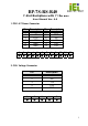
1. PW1: AT Power Connector
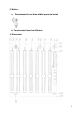
2. CN1: Voltage Connector
Dec. 07, 2007
Pin Description Pin Description
1 PWRGD 7 GND
2 +5V 8 GND
3 +12V 9 -5V
4 -12V 10 +5V
5 GND 11 +5V
6 GND 12 +5V
1 2 3 4 5 6 7 8 9 10 11 12
▓
▓
▓
▓
▓ ▓ ▓ ▓ ▓ ▓ ▓
▓
Pin Description
1 +5V
2 -5V
3 -12V
4 +12V
5 GND
1 2 3 4 5
▓
▓
▓
▓
▓