
Manual

ECW-281B/281B2-R30/N270 Embedded System
Page 33
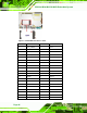
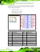
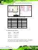
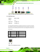
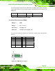
Figure 3-13: USB Connector Pinout Locations
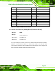
PIN NO. DESCRIPTION PIN NO. DESCRIPTION
1 VCC 2 GND
3 DATA- 4 DATA+
5 DATA+ 6 DATA-
7 GND 8 VCC
Table 3-13: USB Port Connector Pinouts
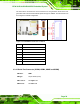
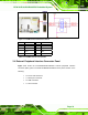
3.4 External Peripheral Interface Connector Panel
777Figure 3-14 shows the ECW-281B/281B2-R30/N270 external peripheral interface
connector (EPIC) panel. The ECW-281B/281B2-R30/N270 EPIC panel consists of the
following:
2 x RJ-45 LAN connectors
1 x Serial port connectors
2 x USB connectors
1 x VGA connector