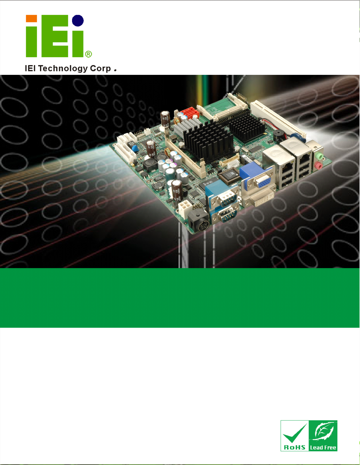
eKINO-945GSE Motherboard MODEL: eKINO-945GSE Mini-ITX Motherboard with Intel® Atom CPU UPS Battery Backup, DDR2, VGA, DVI, LVDS, HDTV Dual PCIe GbE, CompactFlash®, Dual SATA and PCIe Mini User Manual Page i Rev. 1.
eKINO-945GSE Motherboard Revision Date Version Changes 16 May, 2012 1.12 Updated Section 4.2.14: Power Connectors 4 November, 2010 1.11 Minor update 29 July, 2010 1.10 Minor update 11 March, 2009 1.01 Changed product name 23 December, 2008 1.
eKINO-945GSE Motherboard Copyright COPYRIGHT NOTICE The information in this document is subject to change without prior notice in order to improve reliability, design and function and does not represent a commitment on the part of the manufacturer. In no event will the manufacturer be liable for direct, indirect, special, incidental, or consequential damages arising out of the use or inability to use the product or documentation, even if advised of the possibility of such damages.
eKINO-945GSE Motherboard Packing List NOTE: If any of the components listed in the checklist below are missing, please do not proceed with the installation. Contact the IEI reseller or vendor you purchased the eKINO-945GSE from or contact an IEI sales representative directly. To contact an IEI sales representative, please send an email to sales@iei.com.tw. The items listed below should all be included in the eKINO-945GSE package.
eKINO-945GSE Motherboard Table of Contents 1 INTRODUCTION.......................................................................................................... 1 1.1 INTRODUCTION........................................................................................................... 2 1.2 EKINO-945GSE OVERVIEW ...................................................................................... 2 1.2.1 Overview Photo....................................................................................
eKINO-945GSE Motherboard 2.5.5.1 PCIe GbE Ethernet.................................................................................... 18 2.5.5.2 PCIe Mini Card ......................................................................................... 19 2.5.6 Real Time Clock ............................................................................................... 19 2.5.7 SATA Controller ............................................................................................... 19 2.5.
eKINO-945GSE Motherboard 4.2.1 BIOS Battery Connector .................................................................................. 33 4.2.2 CompactFlash® Socket.................................................................................... 34 4.2.3 Digital I/O Connector ...................................................................................... 35 4.2.4 Fan Connector ................................................................................................. 36 4.2.
eKINO-945GSE Motherboard 5.3 UNPACKING .............................................................................................................. 64 5.4 SO-DIMM INSTALLATION ....................................................................................... 65 5.5 CF CARD INSTALLATION .......................................................................................... 66 5.6 UPS INSTALLATION ..................................................................................................
eKINO-945GSE Motherboard 6.1.5 BIOS Menu Bar................................................................................................ 91 6.2 MAIN........................................................................................................................ 92 6.3 ADVANCED ............................................................................................................... 93 6.3.1 CPU Configuration.....................................................................................
eKINO-945GSE Motherboard 8.1 INTRODUCTION....................................................................................................... 157 8.2 MONITORING DC POWER AND SMART BATTERY .................................................... 157 8.2.1 Application Installation.................................................................................. 157 8.2.2 Status Information.......................................................................................... 160 8.2.2.1 DC Detection .......
eKINO-945GSE Motherboard List of Figures Figure 1-1: eKINO-945GSE ............................................................................................................2 Figure 1-2: eKINO-945GSE Overview ...........................................................................................3 Figure 2-1: eKINO-945GSE Dimensions (mm) .............................................................................8 Figure 2-2: External Interface Panel Dimensions (mm) ...................................
eKINO-945GSE Motherboard Figure 4-24: eKINO-945GSE External Peripheral Interface Connector ...................................56 Figure 4-25: Audio Connector .....................................................................................................56 Figure 4-26: RJ-45 Ethernet Connector......................................................................................58 Figure 4-27: RS-232 Serial Port Pinout Locations.....................................................................
eKINO-945GSE Motherboard Figure 7-15: VGA Driver Installation Finish Screen ............................................................... 150 Figure 7-16: LAN Driver Welcome Screen .............................................................................. 151 Figure 7-17: LAN Driver Welcome Screen .............................................................................. 151 Figure 7-18: LAN Driver Installation .......................................................................................
eKINO-945GSE Motherboard List of Tables Table 1-2: Technical Specifications..............................................................................................6 Table 2-1: Supported HDD Specifications..................................................................................17 Table 2-2: Power Consumption...................................................................................................24 Table 3-1: Packing List...............................................................
eKINO-945GSE Motherboard Table 5-1: Jumpers .......................................................................................................................69 Table 5-2: AT/ATX Power Selection Jumper Settings...............................................................70 Table 5-3: Clear CMOS Jumper Settings....................................................................................71 Table 5-4: CF Card Setup Jumper Settings ..................................................................
eKINO-945GSE Motherboard BIOS Menus BIOS Menu 1: Main .......................................................................................................................92 BIOS Menu 2: Advanced ..............................................................................................................94 BIOS Menu 3: CPU Configuration ...............................................................................................95 BIOS Menu 4: IDE Configuration.........................................
eKINO-945GSE Motherboard Chapter 1 1 Introduction Page 1
eKINO-945GSE Motherboard 1.1 Introduction Figure 1-1: eKINO-945GSE The eKINO-945GSE Mini-ITX motherboards have embedded Intel® Atom™ processors. The eKINO-945GSE provides its own UPS by attaching the included battery. The embedded Intel® Atom™ N270 processor has a 1.60 GHz clock speed, a 533 MHz FSB and a 512 KB L2 cache. The eKINO-945GSE also supports one 200-pin 533 MHz 2.0 GB (max.) DDR2 SDRAM SO-DIMM. The board comes with VGA, DVI, HDTV and 18-bit dual-channel LVDS video outputs.
eKINO-945GSE Motherboard Figure 1-2: eKINO-945GSE Overview 1.2.
eKINO-945GSE Motherboard 1 x Infrared connector 1 x Keyboard/mouse connector 1 x LCD backlight inverter connector 1 x LVDS connector 1 x PCIe Mini slot 2 x SATA drive connectors 2 x SATA power connectors 2 x Serial port connectors (RS-232) 1 x Serial port connector (RS-422/485) 1 x SO-DIMM socket 1 x TV output connector 1 x USB pin header (2 ports) The eKINO-945GSE has the following external peripheral interface connectors on the board rear panel.
eKINO-945GSE Motherboard 1.2.3 Technical Specifications eKINO-945GSE technical specifications are listed in Table 1-1. See Chapter 2 for details. 7 Specification eKINO-945GSE Form Factor Mini-ITX System CPU 45 nm 1.60 GHz Intel® Atom™ N270 Front Side Bus (FSB) 533 MHz System Chipset Memory Northbridge: Intel® 945GSE Southbridge: Intel® ICH7M One 200-pin SO-DIMM socket supports one 533 MHz 2.0 GB (max.
eKINO-945GSE Motherboard Specification Watchdog Timer eKINO-945GSE Software programmable 1-255 sec. through the iTE IT8718F super I/O One infrared connector supports Infrared Serial Infrared (SIR) Amplitude Shift Keyed IR (ASKIR) Recommended input voltage: 12-24 VDC Power Supply Maximum input voltage: 9-28 VDC 1 x External 4-pin DIN jack 1 x Internal 2x2 power connector Power Consumption Temperature 1 A @ 12 V (with 1.
eKINO-945GSE Motherboard Chapter 2 2 Detailed Specifications Page 7
eKINO-945GSE Motherboard 2.1 Dimensions 2.1.
eKINO-945GSE Motherboard 2.1.2 External Interface Panel Dimensions External peripheral interface connector panel dimensions are shown in Figure 2-2.
eKINO-945GSE Motherboard 2.2 Data Flow Figure 2-3 shows the data flow between the two on-board chipsets and other components installed on the motherboard and described in the following sections of this chapter.
eKINO-945GSE Motherboard 2.3 Embedded Intel® Atom™ Processor The eKINO-945GSE comes with an embedded 45 nm 1.60 GHz Intel® Atom™ N270 processor. The processor supports a 533 MHz FSB and has a 512 KB L2 cache. The low power processor has a maximum power of 2.5 W. The processor is shown in Figure 2-4 below. Figure 2-4: Chipset 2.3.
eKINO-945GSE Motherboard On-die, primary 32-kB instructions cache and 24-kB write-back data cache 533 MHz source-synchronous front side bus (FSB) 2-Threads support On-die 512-kB, 8-way L2 cache Support for IA 32-bit architecture Intel® Streaming SIMD Extensions-2 and -3 (Intel® SSE2 and Intel® SSE3) support and Supplemental Streaming SIMD Extension 3 (SSSE3) support Micro-FCBGA8 packaging technologies Thermal management support via Intel® Thermal Monitor 1 and Intel Thermal Mo
eKINO-945GSE Motherboard The SO-DIMM socket is shown in Figure 2-4 below. 2.4.2 Graphics The Intel® 945GSE Northbridge chipset has an Intel® Gen. 3.5 integrated graphics engine that supports the following display devices (shown in Figure 2-4): Analog CRT LVDS TV-Out SDVO ports 2.4.2.1 Analog CRT (VGA) A DB-15 VGA connector on the external peripheral interface connector panel is interfaced to the Intel® 945GSE graphics engine.
eKINO-945GSE Motherboard Supports RCA or S-VIDEO connectivity Supports HDTV with the following resolutions: o o o o 480p 720p 1080i 1080p 2.4.2.4 SDVO and DVI The SDVO is connected to the DVI output through the Silicon Image Sil1362. The Intel® 945GSE internal graphics engine has the following SDVO output features: Concurrent operation of PCIe x 1 with SDVO Two SDVO ports supported o o o o o SDVO is muxed onto the PCIe pins DVI 1.
eKINO-945GSE Motherboard Figure 2-5: Intel® ICH7M Southbridge Chipset Complies with PCI Express Base Specification, Revision 1.0a Complies with PCI Local Bus Specification, Revision 2.
eKINO-945GSE Motherboard Supports the four USB 2.0 devices on the eKINO-945GSE with four UHCI controllers and one EHCI controller Complies with System Management Bus (SMBus) Specification, Version 2.0 Supports Audio Codec ’97 (AC’97) Revision 2.3 Supports Intel® High Definition Audio Contains Low Pin Count (LPC) interface Supports Firmware Hub (FWH) interface Serial peripheral interface support 2.5.
eKINO-945GSE Motherboard Specification Ultra ATA/100 Ultra ATA/66 Ultra ATA/33 IDE devices 2 2 2 PIO Mode 0–4 0–4 0–4 PIO Max Transfer Rate 16.6 MB/s 16.6 MB/s 16.6 MB/s DMA/UDMA designation UDMA 5 UDMA 4 UDMA 2 DMA/UDMA Max Transfer 100 MB/s 66 MB/s 33 MB/s Controller Interface 5V 5V 5V Table 2-1: Supported HDD Specifications 2.5.2.2 CompactFlash® Slot The CompactFlash® slot on the eKINO-945GSE is interfaced through the IDE interface on the Intel® ICH7M Southbridge.
eKINO-945GSE Motherboard 2.5.5 PCIe Bus The Intel® ICH7M Southbridge chipset has four PCIe lanes. Two of the four PCIe lanes are interfaced to PCIe GbE controllers. Another land is connected to the PCIe Mini card slot. 2.5.5.1 PCIe GbE Ethernet Two PCIe lanes are connected to two Realtek RTL8111C PCIe GbE controllers shown in Figure 2-5. The Realtek RTL8111C PCIe GbE controllers combine a triple-speed IEEE 802.
eKINO-945GSE Motherboard Supports PCI MSI (Message Signaled Interrupt) and MSI-X Supports Receive-Side Scaling (RSS) 2.5.5.2 PCIe Mini Card One PCIe lane is connected to a PCIe Mini card slot shown in Figure 2-5. The PCIe Mini card slot contains a PCIe x1 and USB 2.0 interface. PCIe Mini cards can utilize either of these two interfaces, depending on design requirements. 2.5.
eKINO-945GSE Motherboard The six USB ports implemented on the eKINO-945GSE are connected to three internal connectors and one external connector shown in Figure 2-5. 2.6 LPC Bus Components The iTE IT8718F LPC bus is connected to components listed below (and shown in Figure 2-5): BIOS chip Super I/O chip Serial port chip 2.6.1 BIOS Chipset The BIOS chipset has a licensed copy of AMI BIOS installed on the chipset.
eKINO-945GSE Motherboard Some of the Super I/O features are described in more detail below: 2.6.2.1 LPC Interface The LPC interface on the Super I/O complies with the Intel® Low Pin Count Specification Rev. 1.0. The LPC interface supports both LDRQ# and SERIRQ protocols as well as PCI PME# interfaces. 2.6.2.2 16C550 UARTs The onboard Super I/O has two integrated 16C550 UARTs that can support the following: Two standard serial ports IrDa 1.0 and ASKIR protocols 2.6.2.
eKINO-945GSE Motherboard Supports multiple keyboard power on events Supports mouse double-click and/or mouse move power on events 2.6.2.7 Parallel Port The multi-mode high-performance parallel port supports the bi-directional Standard Parallel Port (SPP), the Enhanced Parallel Port (EPP) and the Extended Capabilities Port (ECP) modes. 2.6.3 Fintek F81216D LPC Serial Port Chip The Fintek F81216D chipset enables the addition of two additional UART serial ports (COM3 and COM4).
eKINO-945GSE Motherboard Voltage inputs on the eKINO-945GSE Super I/O Enhanced Hardware Monitor monitors the following voltages: CPU Core +1.05 V +3.30 V +5.00 V +12 V +1.5 V +1.8 V +5 VSB VBAT The values for the above environmental parameters are all recorded in the BIOS Hardware Health Configuration menu. 2.7.2 Operating Temperature and Temperature Control The maximum and minimum operating temperatures for the eKINO-945GSE are listed below.
eKINO-945GSE Motherboard Voltage Current +12 V 1.
eKINO-945GSE Motherboard Chapter 3 3 Unpacking Page 25
eKINO-945GSE Motherboard 3.1 Anti-static Precautions WARNING! Failure to take ESD precautions during the installation of the eKINO-945GSE may result in permanent damage to the eKINO-945GSE and severe injury to the user. Electrostatic discharge (ESD) can cause serious damage to electronic components, including the eKINO-945GSE. Dry climates are especially susceptible to ESD.
eKINO-945GSE Motherboard 3.3 Unpacking Checklist NOTE: If any of the components listed in the checklist below are missing, do not proceed with the installation. Contact the IEI reseller or vendor the eKINO-945GSE was purchased from or contact an IEI sales representative directly by sending an email to sales@iei.com.tw. 3 3.3.
eKINO-945GSE Motherboard Quantity Item and Part Number 1 Utility CD 1 Quick Installation Guide Image Table 3-1: Packing List 3.3.
eKINO-945GSE Motherboard Item and Part Number Image PCIe Mini wireless LAN card 802.11b/g (P/N: WMPCIE-V01-R20) 12 V power adapter (P/N: FSP0601AD101C746-RS) 19 V power adapter (P/N: 6300012P0AAB-RS) 4S2P AUPS battery kit (14.8 V, 3800 mAH) (P/N: BATKIT-4S2P3800-R10) *Requires over 18 V power input 4S2P battery (14.8 V, 3800 mAH) (P/N: BAT-LI-4S2P3800) *Requires over 18 V power input 2S2P AUPS battery kit (7.4 V, 3800 mAH) (P/N: BATKIT-2S2P3800-R10) *Requires 12 V power input 2S2P battery (7.
eKINO-945GSE Motherboard Chapter 4 4 Connectors Page 30
eKINO-945GSE Motherboard 4.1 Peripheral Interface Connectors This chapter outlines all internal and external connectors on the eKINO-945GSE. 4.1.1 Layout Figure 4-1 shows the on-board peripheral connectors, rear panel peripheral connectors 8 and on-board jumpers.
eKINO-945GSE Motherboard 4.1.2 Internal Peripheral Interface Connectors Table 4-1 shows a list of the peripheral interface connectors on the eKINO-945GSE. 8 Detailed descriptions of these connectors can be found below.
eKINO-945GSE Motherboard Connector Type Label TV output connector 6-pin header TV1 USB connector (2 ports) 8-pin header USB1 Table 4-1: Peripheral Interface Connectors 4.1.3 External Interface Panel Connectors Table 4-2 lists the rear panel connectors on the eKINO-945GSE. Detailed descriptions of 8 these connectors can be found in Section 1H4.3 on page 55.
eKINO-945GSE Motherboard The battery connector is connected to a backup battery. The battery connector is also used to reset the CMOS memory if the incorrect BIOS settings have been made and the system cannot boot up. Figure 4-2: Battery Connector Location Pin No. Description 1 Battery+ 2 Ground Table 4-3: Battery Connector Pinouts 4.2.
eKINO-945GSE Motherboard Figure 4-3: CF Card Socket Location 4.2.3 Digital I/O Connector CN Label: DIO1 CN Type: 10-pin header (2x5) CN Location: See Figure 4-4 CN Pinouts: See Table 4-4 The digital input/output connector is managed through a Super I/O chip. The DIO connector pins are user programmable.
eKINO-945GSE Motherboard Figure 4-4: Digital I/O Connector Locations Pin No. Description Pin No. Description 1 GND 2 VCC 3 Output 3 4 Output 2 5 Output 1 6 Output 0 7 Input 3 8 Input 2 9 Input 1 10 Input 0 Table 4-4: DIO Connector Pinouts 4.2.4 Fan Connector CN Label: J1 CN Type: 3-pin header CN Location: See Figure 4-5 CN Pinouts: See Table 4-5 8 8 The cooling fan connector provides a 12 V, 500mA current to the cooling fan.
eKINO-945GSE Motherboard Figure 4-5: CPU Fan Connector Location Pin No. Description 1 Fan Speed Detect 2 +12 V 3 GND Table 4-5: CPU Fan Connector Pinouts 4.2.5 Front Panel Connector CN Label: F_PANEL1 CN Type: 14-pin header (2x7) CN Location: See Figure 4-6 CN Pinouts: See Table 4-6 The front panel connector connects to external switches and indicators to monitor and controls the motherboard.
eKINO-945GSE Motherboard Power LED HDD LED Figure 4-6: Front Panel Connector Pinout Locations Function Pin Description Function Pin Description Power LED 1 Power LED + Speaker 2 Speaker + 3 N/C 4 N/C 5 Power LED - 6 N/C 7 Power button + 8 Speaker - 9 Power button - 10 N/C 11 HDD LED + 12 Reset + 13 HDD LED - 14 Reset - Power Button HDD LED Reset Table 4-6: Front Panel Connector Pinouts 4.2.
eKINO-945GSE Motherboard Figure 4-7: IDE Device Connector Locations 4.2.7 Infrared Interface Connector CN Label: IR1 CN Type: 5-pin header (1x5) CN Location: See Figure 4-8 CN Pinouts: See Table 4-7 8 8 The infrared interface connector supports both Serial Infrared (SIR) and Amplitude Shift Key Infrared (ASKIR) interfaces.
eKINO-945GSE Motherboard Figure 4-8: Infrared Connector Pinout Locations Pin No. Description 1 VCC 2 NC 3 IR-RX 4 GND 5 IR-TX Table 4-7: Infrared Connector Pinouts 4.2.8 Keyboard/Mouse Connector CN Label: MS/KB1 CN Type: 6-pin box header (1x6) CN Location: See Figure 4-9 CN Pinouts: See Table 4-8 The keyboard and mouse connector is for connecting a PS/2 keyboard, PS/2 mouse, or both, to the board.
eKINO-945GSE Motherboard Figure 4-9: Keyboard/Mouse Connector Location Pin No. Description 1 Power (5 V) 2 Mouse data 3 Mouse clock 4 Keyboard data 5 Keyboard clock 6 Ground Table 4-8: Keyboard/Mouse Connector Pinouts 4.2.
eKINO-945GSE Motherboard Figure 4-10: LCD Backlight Connector Pinout Locations Pin No. Description 1 Brightness 2 GND 3 12 V 4 GND 5 Backlight enable Table 4-9: LCD Backlight Connector Pinouts 4.2.10 LED Connector CN Label: J3 CN Type: 6-pin box header CN Location: See Figure 4-11 CN Pinouts: See Table 4-10 The LED connector connects to LED indicators showing the status of the connected UPS battery.
eKINO-945GSE Motherboard Figure 4-11: LED Connector Location Pin No Description Function 1 Battery discharge+ Discharge 2 Battery discharge- LED 3 Battery charging+ Charge 4 Battery charging- LED 5 DC+ Power LED 6 DC- (DC-IN) Table 4-10: LED Connector Pinouts 4.2.
eKINO-945GSE Motherboard The 30-pin LVDS LCD connector can be connected to single channel or dual channel, 18-bit or 36-bit LVDS panel. Figure 4-12: LVDS LCD Connector Pinout Locations Pin No. Description Pin No.
eKINO-945GSE Motherboard Pin No. Description Pin No. Description 29 LCDVCC 30 LCDVCC Table 4-11: LVDS LCD Port Connector Pinouts 4.2.12 MCU LAN Connector CN Label: J10 CN Type: 10-pin pin header CN Location: See Figure 4-13 CN Pinouts: See Table 4-12 The MCU LAN connector allows remote monitoring of the UPS MCU. Figure 4-13: MCU LAN Connector Location Pin No.
eKINO-945GSE Motherboard Pin No. Description 8 Pair 2 9 TX+ 10 TX- Table 4-12: MCU LAN Connector Pinouts 4.2.13 PCIe Mini Card Slot CN Label: MINI_PCIE1 CN Type: 52-pin Mini PCIe Card Slot CN Location: See Figure 4-14 8 The PCIe mini card slot enables a PCIe mini card expansion module to be connected to the board. Cards supported include among others wireless LAN (WLAN) cards.
eKINO-945GSE Motherboard 4.2.14 Power Connectors CN Label: CN2 CN Type: 4-pin power connectors CN Location: See Figure 4-15 CN Pinouts: See Table 4-13 The power connectors connect to a 9~28 V power supply. Figure 4-15: Power Connector Location Pin No.
eKINO-945GSE Motherboard 4.2.15 SATA Drive Connectors CN Label: SATA1, SATA2 CN Type: 7-pin SATA drive connectors CN Location: See Figure 4-16 CN Pinouts: See Table 4-14 8 8 The four SATA drive connectors are each connected to a first generation SATA drive. First generation SATA drives transfer data at speeds as high as 150 Mb/s. The SATA drives can be configured in a RAID configuration. Figure 4-16: SATA Drive Connector Locations 4.2.
eKINO-945GSE Motherboard The SATA power connectors provide power to SATA drives. These power connectors are connected to the UPS in case of power loss. Do not connect SATA drives to the main power supply. Figure 4-17: SATA Power Connector Location Pin No.
eKINO-945GSE Motherboard 4.2.17 Serial Port Connectors (RS-232) CN Label: COM3 and COM4 CN Type: 10-pin header (2x5) CN Location: See Figure 4-18 CN Pinouts: See Table 4-15 8 8 The 10-pin serial port connectors provide RS-232 serial communications channels. The COM serial port connectors can be connected to external RS-232 serial port devices. COM3 uses JP2 for RS-422 and RS-485 connectivity. Figure 4-18: RS-232 Connector Pinout Locations Pin No. Description Pin No.
eKINO-945GSE Motherboard Pin No. Description Pin No. Description 9 Ground (GND) 10 N/C Table 4-15: RS-232 Connector Pinouts 4.2.18 Serial Port Connectors (RS-422/485) CN Label: JP2 CN Type: 6-pin header (2x3) CN Location: See Figure 4-19 CN Pinouts: See Table 4-16 8 The serial port connector provides the RS-422 and RS-485 pins for serial port COM3. JP1 sets COM3 to RS-232, RS-422 or RS-485, use the COM3 connector for RS-232 and the connectors on JP2 for RS-422 or RS-485 connectivity.
eKINO-945GSE Motherboard 4.2.19 SO-DIMM Socket CN Label: DIMM1 CN Type: DDR2 SO-DIMM socket CN Location: See Figure 4-20 The digital input/output connector is managed through a Super I/O chip. The DIO connector pins are user programmable. Figure 4-20: SO-DIMM Location 4.2.20 SPDIF Connector CN Label: SPDIF1 CN Type: 5-pin header CN Location: See Figure 4-21 CN Pinouts: See Table 4-17 Use the SPDIF connector to connect digital audio devices to the system.
eKINO-945GSE Motherboard Figure 4-21: SPDIF Connector Location Pin Description 1 VCC5 2 NC 3 SPDIF OUT 4 GND AUDIO 5 SPDIF IN Table 4-17: SPDIF Connector Pinouts 4.2.21 TV Out Connector CN Label: TV1 CN Type: 6-pin header (2x3) CN Location: See Figure 4-22 CN Pinouts: See Table 4-18 The 2x3 pin TV out connector connects to a TV output by using an S-Video or RCA connector. The TV out connector makes displaying media data on a television easier.
eKINO-945GSE Motherboard Figure 4-22: TV Connector Pinout Locations Pin No. Description Pin No. Description 1 GND 2 AGREEN_Y 3 GND 4 ARED_C 5 GND 6 ABLUE_CVBS Table 4-18: TV Port Connector Pinouts 4.2.22 USB Connectors CN Label: USB1 CN Type: 8-pin header (2x4) CN Location: See Figure 4-23 CN Pinouts: See Table 4-19 8 8 The 2x4 USB pin connector provides connectivity to two USB 1.1 or two USB 2.0 ports. The USB connector can support two USB devices.
eKINO-945GSE Motherboard Figure 4-23: USB Connector Pinout Locations Pin No. Description Pin No. Description USB Connector 1 USB Connector 2 1 VCC 2 GND 3 DATA1- 4 DATA2+ 5 DATA1+ 6 DATA2- 7 GND 8 VCC Table 4-19: USB Port Connector Pinouts 4.3 External Peripheral Interface Connector Panel Figure 4-24 shows the eKINO-945GSE external peripheral interface connector (EPIC) 8 panel.
eKINO-945GSE Motherboard Figure 4-24: eKINO-945GSE External Peripheral Interface Connector 4.3.1 Audio Connector CN Label: AUDIO1 CN Type: 2 x audio jacks CN Location: See Figure 4-24 The two audio jacks connect to external audio devices as specified below. Line Out port (Lime): Connects to a headphone or a speaker. With multi-channel configurations, this port can also connect to front speakers. Microphone (Pink): Connects a microphone. Figure 4-25: Audio Connector 4.3.
eKINO-945GSE Motherboard The 24-pin Digital Visual Interface (DVI) connector connects to high-speed, high-resolution digital displays. The DVI-I connector supports both digital and analog signals.
eKINO-945GSE Motherboard Pin Description Pin Description 4 MDIA1- 8 MDIA0+ Table 4-21: LAN Pinouts Figure 4-26: RJ-45 Ethernet Connector The RJ-45 Ethernet connector has two status LEDs, one green and one yellow. The green LED indicates activity on the port and the yellow LED indicates the port is linked. See Table 4-22. 8 Status Description Status Description Green Activity Yellow Linked Table 4-22: RJ-45 Ethernet Connector LEDs 4.3.
eKINO-945GSE Motherboard Pin No. Description 5 GND Pin No. Description Table 4-23: RS-232 Serial Port Pinouts Figure 4-27: RS-232 Serial Port Pinout Locations 4.3.5 USB Connectors CN Label: LAN/USB1 and LAN/USB2 CN Type: USB port CN Location: See Figure 4-24 CN Pinouts: See Table 4-24 8 8 The eKINO-945GSE has one external USB 2.0 port. The ports connect to both USB 2.0 and USB 1.1 devices. Pin No.
eKINO-945GSE Motherboard 4.3.6 VGA Connector CN Label: VIDEO1 (top) CN Type: 15-pin Female CN Location: See Figure 4-24 CN Pinouts: See Figure 4-28 and Table 4-25 8 8 8 The eKINO-945GSE has a single 15-pin female connector for connectivity to standard display devices.
eKINO-945GSE Motherboard Chapter 5 5 Installation Page 61
eKINO-945GSE Motherboard 5.1 Anti-static Precautions WARNING: Failure to take ESD precautions during the installation of the eKINO-945GSE may result in permanent damage to the eKINO-945GSE and severe injury to the user. Electrostatic discharge (ESD) can cause serious damage to electronic components, including the eKINO-945GSE. Dry climates are especially susceptible to ESD.
eKINO-945GSE Motherboard 5.2 Installation Considerations NOTE: The following installation notices and installation considerations should be read and understood before the eKINO-945GSE is installed. All installation notices pertaining to the installation of the eKINO-945GSE should be strictly adhered to. Failing to adhere to these precautions may lead to severe damage of the eKINO-945GSE and injury to the person installing the motherboard. 5.2.
eKINO-945GSE Motherboard Before and during the installation of the eKINO-945GSE DO NOT: DO NOT remove any of the stickers on the PCB board. These stickers are required for warranty validation. DO NOT use the product before verifying all the cables and power connectors are properly connected. DO NOT allow screws to come in contact with the PCB circuit, connector pins, or its components. 5.2.
eKINO-945GSE Motherboard contact the eKINO-945GSE vendor reseller/vendor where the eKINO-945GSE was purchased or contact an IEI sales representative. 5.4 SO-DIMM Installation WARNING: Using incorrectly specified SO-DIMM may cause permanently damage the eKINO-945GSE. Please make sure the purchased SO-DIMM complies with the memory specifications of the eKINO-945GSE. SO-DIMM specifications compliant with the eKINO-945GSE are listed in Chapter 2.
eKINO-945GSE Motherboard Step 3: Insert the SO-DIMM. Push the SO-DIMM chip into the socket at an angle. (See Figure 5-1) Step 4: Open the SO-DIMM socket arms. Gently pull the arms of the SO-DIMM socket out and push the rear of the SO-DIMM down. (See Figure 5-1) Step 5: Secure the SO-DIMM. Release the arms on the SO-DIMM socket. They clip into place and secure the SO-DIMM in the socket.Step 0: 5.5 CF Card Installation NOTE: The eKINO-945GSE can support both CF Type I cards and CF Type II cards.
eKINO-945GSE Motherboard Figure 5-2: CF Card Installation Page 67
eKINO-945GSE Motherboard 5.6 UPS Installation To install the UPS, connect the UPS battery to the motherboard and connect the motherboard to the 9-28 V power supply as shown in the diagram below. Figure 5-3: UPS Installation 5.7 Jumper Settings NOTE: A jumper is a metal bridge used to close an electrical circuit. It consists of two or three metal pins and a small metal clip (often protected by a plastic cover) that slides over the pins to connect them.
eKINO-945GSE Motherboard Before the eKINO-945GSE is installed in the system, the jumpers must be set in accordance with the desired configuration. The jumpers on the eKINO-945GSE are listed in Table 5-1.
eKINO-945GSE Motherboard Figure 5-4: Jumpers 5.7.1 AT/ATX Selection Jumper Label: ATXCTL1 Jumper Type: 2-pin header Jumper Settings: See Table 5-2 Jumper Location: See Figure 5-4 The AT/ATX Power Selection jumper specifies the systems power mode as AT or ATX. Power Selection jumper settings are shown in Table 5-2.
eKINO-945GSE Motherboard 5.7.2 Clear CMOS Jumper Jumper Label: J_CMOS1 Jumper Type: 3-pin header Jumper Settings: See Table 5-3 Jumper Location: See Figure 5-4 8 8 If the eKINO-945GSE fails to boot due to improper BIOS settings, the clear CMOS jumper clears the CMOS data and resets the system BIOS information. To do this, use the jumper cap to close pins 2 and 3 for a few seconds then reinstall the jumper clip back to pins 1 and 2.
eKINO-945GSE Motherboard The CF Card Setup jumper sets the CF Type I card or CF Type II cards as either the slave device or the master device. CF Card Setup jumper settings are shown in Table 5-4. Pin Setting Description Open Slave Closed Master Table 5-4: CF Card Setup Jumper Settings 5.7.
eKINO-945GSE Motherboard Pin Setting Description Open 640 x 480 (18-bit) 1-2 800 x 480 (18-bit) 3-4 800 x 600 (18-bit) 1-2, 3-4 1024 x 768 (18-bit) 5-6 1280 x 1024 (18-bit) 1-2, 5-6 1400 x 1050 (18-bit) 3-4, 5-6 1400 x 900 (18-bit) 1-2, 3-4, 5-6 1600 x 1200 (18-bit) Table 5-6: LCD Panel Type Selection Jumper Settings 5.7.6 LVDS Voltage Selection WARNING: Permanent damage to the screen and eKINO-945GSE may occur if the wrong voltage is selected with this jumper.
eKINO-945GSE Motherboard 5.7.7 UPS Enable/Disable Jumper Label: JP3 Jumper Type: 2-pin header Jumper Settings: See Table 5-8 Jumper Location: See Figure 5-4 When this jumper is closed, the system will use the battery when needed, when open the system will not use the battery. Pin Setting Description Open Don't use the battery backup Closed Use the battery function Table 5-8: UPS Enable/Disable Jumper Settings 5.7.
eKINO-945GSE Motherboard 5.8 Chassis Installation 5.8.1 Airflow WARNING: Airflow is critical to the cooling of the CPU and other onboard components. The chassis in which the eKINO-945GSE must have air vents to allow cool air to move into the system and hot air to move out. The eKINO-945GSE must be installed in a chassis with ventilation holes on the sides allowing airflow to travel through the heat sink surface.
eKINO-945GSE Motherboard Quantity Type 1 Power cable 1 Dual RS-232 cable Table 5-10: IEI Provided Cables Some optional items that can be purchased separately and installed on the eKINO-945GSE include: Dual port USB cable Parallel port cable RS-232/422/485 cable ATX power cable HDTV out cable 5.9.1 ATA Flat Cable Connection The ATA 66/100 flat cable connects to the eKINO-945GSE to one or two IDE devices.
eKINO-945GSE Motherboard Figure 5-5: IDE Cable Connection Step 3: Connect the cable to an IDE device. Connect the two connectors on the other side of the cable to one or two IDE devices. Make sure that pin 1 on the cable corresponds to pin 1 on the connector. Step 0: 5.9.2 SATA Drive Connection The eKINO-945GSE is shipped with two SATA drive cables and one SATA drive power cable. To connect the SATA drives to the connectors, please follow the steps below. Step 1: Locate the connectors.
eKINO-945GSE Motherboard Figure 5-6: SATA Drive Cable Connection Step 3: Connect the cable to the SATA disk. Connect the connector on the other end of the cable to the connector at the back of the SATA drive. See Figure 5-7. 9 Step 4: Connect the SATA power cable. Connect the SATA power connector to the back of the SATA drive. See Figure 5-7.
eKINO-945GSE Motherboard Figure 5-7: SATA Power Drive Connection 5.9.3 Dual RS-232 Cable with Slot Bracket The dual RS-232 cable slot connector consists of two connectors attached to two independent cables. Each cable is then attached to a D-sub 9 male connector that is mounted onto a slot. To install the dual RS-232 cable, please follow the steps below. Step 1: Locate the connectors. The locations of the RS-232 connectors are shown in Chapter 3. Step 2: Insert the cable connectors.
eKINO-945GSE Motherboard Figure 5-8: Dual RS-232 Cable Installation Step 3: Secure the bracket. The dual RS-232 connector has two D-sub 9 male connectors secured on a bracket. To secure the bracket to the chassis please refer to the reference material that came with the chassis.Step 0: 5.9.4 USB Cable (Dual Port) with Slot Bracket The eKINO-945GSE is shipped with a dual port USB 2.0 cable. To connect the USB cable connector, please follow the steps below. Step 1: Locate the connectors.
eKINO-945GSE Motherboard Step 2: Align the connectors. The cable has two connectors. Correctly align pin 1on each cable connector with pin 1 on the eKINO-945GSE USB connector. Step 3: Insert the cable connectors. Once the cable connectors are properly aligned with the USB connectors on the eKINO-945GSE, connect the cable connectors to the on-board connectors. See Figure 5-9. Figure 5-9: Dual USB Cable Connection Step 4: Attach the bracket to the chassis. The USB 2.0 connectors are attached to a bracket.
eKINO-945GSE Motherboard 5.9.5 Parallel Port Cable without Bracket The optional parallel port (LPT) cable respectively connects the on-board LPT 26-pin box header to an external LPT device (like a printer). The cable comprises a 26-pin female header, to be connected to the on-board LPT box-header, on one side and on the other side a standard external LPT connector. To connect the LPT cable, please follow the steps below. Step 1: Locate the connector. The LPT connector location is shown in Chapter 4.
eKINO-945GSE Motherboard Step 5: Connect LPT device. Once the LPT interface connector is connected to the chassis, the LPT device can be connected to the LPT interface connector. See Figure 5-11Step 0:\ Figure 5-11: Connect the LPT Device 5.10 External Peripheral Interface Connection The following external peripheral devices can be connected to the external peripheral interface connectors.
eKINO-945GSE Motherboard 5.10.1 LAN Connection (Single Connector) There are two external RJ-45 LAN connectors. The RJ-45 connectors enable connection to an external network. To connect a LAN cable with an RJ-45 connector, please follow the instructions below. Step 1: Locate the RJ-45 connectors. The locations of the USB connectors are shown in Chapter 4. Step 2: Align the connectors. Align the RJ-45 connector on the LAN cable with one of the RJ-45 connectors on the eKINO-945GSE. See Figure 5-12.
eKINO-945GSE Motherboard Step 1: Locate the dual PS/2 connector. The location of the PS/2 connector is shown in Chapter 3. Step 2: Insert the keyboard/mouse connector. Insert the PS/2 connector on the end of the PS/2 y-cable into the external PS/2 connector. See Figure 5-13. Figure 5-13: PS/2 Keyboard/Mouse Connector Step 3: Connect the keyboard and mouse. Connect the keyboard and mouse to the appropriate connector.
eKINO-945GSE Motherboard Step 1: Locate the DB-9 connector. The location of the DB-9 connector is shown in Chapter 3. Step 2: Insert the serial connector. Insert the DB-9 connector of a serial device into the DB-9 connector on the external peripheral interface. See Figure 5-14. 9 Figure 5-14: Serial Device Connector Step 3: Secure the connector. Secure the serial device connector to the external interface by tightening the two retention screws on either side of the connector. Step0: 5.10.
eKINO-945GSE Motherboard Step 2: Insert a USB Series "A" plug. Insert the USB Series "A" plug of a device into the USB Series "A" receptacle on the external peripheral interface. See Figure 5-15.Step 0: 9 Figure 5-15: USB Connector 5.10.5 VGA Monitor Connection The eKINO-945GSE has a single female DB-15 connector on the external peripheral interface panel. The DB-15 connector is connected to a CRT or VGA monitor. To connect a monitor to the eKINO-945GSE, please follow the instructions below.
eKINO-945GSE Motherboard Step 3: Insert the VGA connector. Once the connectors are properly aligned with the insert the male connector from the VGA screen into the female connector on the eKINO-945GSE. See Figure 5-16. 9 Figure 5-16: VGA Connector Step 4: Secure the connector. Secure the DB-15 VGA connector from the VGA monitor to the external interface by tightening the two retention screws on either side of the connector.
eKINO-945GSE Motherboard Chapter 6 6 BIOS Setup Page 89
eKINO-945GSE Motherboard 6.1 Introduction A licensed copy of AMI BIOS is preprogrammed into the ROM BIOS. The BIOS setup program allows users to modify the basic system configuration. This chapter describes how to access the BIOS setup program and the configuration options that may be changed. 6.1.1 Starting Setup The AMI BIOS is activated when the computer is turned on. The setup program can be activated in one of two ways. 1. Press the DELETE key as soon as the system is turned on or 2.
eKINO-945GSE Motherboard Key Function F1 key General help, only for Status Page Setup Menu and Option Page Setup Menu F2 /F3 key Change color from total 16 colors. F2 to select color forward. F10 key Save all the CMOS changes, only for Main Menu Table 6-1: BIOS Navigation Keys 6.1.3 Getting Help When F1 is pressed a small help window describing the appropriate keys to use and the possible selections for the highlighted item appears. To exit the Help Window press ESC or the F1 key again. 6.1.
eKINO-945GSE Motherboard 6.2 Main The Main BIOS menu (BIOS Menu 1) appears when the BIOS Setup program is entered. 9 The Main menu gives an overview of the basic system information. BIOS Menu 1: Main Î System Overview The System Overview lists a brief summary of different system components. The fields in System Overview cannot be changed.
eKINO-945GSE Motherboard System Memory: Displays the auto-detected system memory. o Size: Lists memory size The System Overview field also has two user configurable fields: Î System Time [xx:xx:xx] Use the System Time option to set the system time. Manually enter the hours, minutes and seconds. Î System Date [xx/xx/xx] Use the System Date option to set the system date. Manually enter the day, month and year. 6.
eKINO-945GSE Motherboard BIOS Menu 2: Advanced Page 94
eKINO-945GSE Motherboard 6.3.1 CPU Configuration Use the CPU Configuration menu (BIOS Menu 3) to view detailed CPU specifications 9 and configure the CPU.
eKINO-945GSE Motherboard 6.3.2 IDE Configuration Use the IDE Configuration menu (BIOS Menu 4) to change and/or set the configuration 9 of the IDE devices installed in the system. BIOS Menu 4: IDE Configuration Î ATA/IDE Configurations [Compatible] Use the ATA/IDE Configurations option to configure the ATA/IDE controller. Î Disabled Disables the on-board ATA/IDE controller. Î Compatible Configures the on-board ATA/IDE controller to be in compatible mode.
eKINO-945GSE Motherboard Î Enhanced Configures the on-board ATA/IDE controller to be in DEFAULT Enhanced mode. In this mode, IDE channels and SATA channels are separated. This mode supports up to 6 storage devices. Some legacy OS do not support this mode. Î Legacy IDE Channels [PATA Pri, SATA Sec] Î SATA Only Î SATA Pri, PATA Sec Only the SATA drives are enabled. DEFAULT The IDE drives are enabled on the Primary IDE channel. The SATA drives are enabled on the Secondary IDE channel.
eKINO-945GSE Motherboard 6.3.2.1 IDE Master, IDE Slave Use the IDE Master and IDE Slave configuration menu to view both primary and secondary IDE device details and configure the IDE devices connected to the system. BIOS Menu 5: IDE Master and IDE Slave Configuration Î Auto-Detected Drive Parameters The “grayed-out” items in the left frame are IDE disk drive parameters automatically detected from the firmware of the selected IDE disk drive.
eKINO-945GSE Motherboard Block Mode: Block mode boosts IDE drive performance by increasing the amount of data transferred. Only 512 bytes of data can be transferred per interrupt if block mode is not used. Block mode allows transfers of up to 64 KB per interrupt. PIO Mode: Indicates the PIO mode of the installed device. Async DMA: Indicates the highest Asynchronous DMA Mode that is supported. Ultra DMA: Indicates the highest Synchronous DMA Mode that is supported. S.M.A.R.T.
eKINO-945GSE Motherboard Î LBA/Large Mode [Auto] Use the LBA/Large Mode option to disable or enable BIOS to auto detects LBA (Logical Block Addressing). LBA is a method of addressing data on a disk drive. In LBA mode, the maximum drive capacity is 137 GB. Î BIOS is prevented from using the LBA mode control on Disabled the specified channel. Î Auto DEFAULT BIOS auto detects the LBA mode control on the specified channel.
eKINO-945GSE Motherboard Î 3 PIO mode 3 selected with a maximum transfer rate of 11.1 MB/s Î 4 PIO mode 4 selected with a maximum transfer rate of 16.6 MB/s (This setting generally works with all hard disk drives manufactured after 1999. For other disk drives, such as IDE CD-ROM drives, check the specifications of the drive.) Î DMA Mode [Auto] Use the DMA Mode BIOS selection to adjust the DMA mode options. Î Auto DEFAULT BIOS auto detects the DMA mode.
eKINO-945GSE Motherboard Î Ultra DMA mode 3 selected with a maximum data transfer UDMA3 rate of 44 MB/s (To use this mode, it is required that an 80-conductor ATA cable is used.) Î Ultra DMA mode 4 selected with a maximum data transfer UDMA4 rate of 66.6 MB/s (To use this mode, it is required that an 80-conductor ATA cable is used.) Î Ultra DMA mode 5 selected with a maximum data transfer UDMA5 rate of 99.9 MB/s (To use this mode, it is required that an 80-conductor ATA cable is used.) Î S.M.A.
eKINO-945GSE Motherboard 6.3.3 Super IO Configuration Use the Super IO Configuration menu (BIOS Menu 6) to set or change the 9 configurations for the FDD controllers, parallel ports and serial ports. BIOS Menu 6: Super IO Configuration Î Serial Port1 Address [3F8/IRQ4] Use the Serial Port1 Address option to select the I/O and IRQ base addresses.
eKINO-945GSE Motherboard Î Normal IrDA ASK IR Default Serial Port2 Address [2F8/IRQ3] Use the Serial Port2 Address option to select the I/O and IRQ addresses.
eKINO-945GSE Motherboard Î 10 Select RS232 or RS422/RS485 [RS232] Use the Select RS232 or RS422/RS485 option to select the transmitting and receiving mode. Î RS232 RS422/485 Default Serial Port4 Address [2E8] Use the Serial Port 4 Address option to set the I/O address.
eKINO-945GSE Motherboard Î 2E0 Î DEFAULT The assigned I/O address is 2E0 Serial Port 6 IRQ [11] Use the Serial Port 4 IRQ option selects the IRQ. 11 10 DEFAULT 6.3.4 Hardware Health Configuration The Hardware Health Configuration menu (BIOS Menu 7) shows the operating 9 temperature, fan speeds and system voltages. BIOS Menu 7: Hardware Health Configuration Î CPU FAN Mode Setting [Full On Mode] Use the CPU FAN Mode Setting option to configure the second fan.
eKINO-945GSE Motherboard Î Full On Mode DEFAULT Î Automatic mode Fan is on all the time Fan is off when the temperature is low enough. Parameters must be set by the user. Î PWM Manual mode Pulse width modulation set manually When the CPU FAN Mode Setting option is in the Automatic Mode, the following parameters can be set. CPU Temp. Limit of OFF CPU Temp.
eKINO-945GSE Motherboard Î CPU Temp. Limit of Start [020] WARNING: Setting this value too high may cause the fan to start only when the CPU is at a high temperature and therefore cause the system to be damaged. The CPU Temp. Limit of Start option can only be set if the CPU FAN Mode Setting option is set to Automatic Mode. Use the CPU Temp. Limit of Start option to select the CPU temperature at which the cooling fan should automatically turn on.
eKINO-945GSE Motherboard 0 PWM 1 PWM 2 PWM 4 PWM 8 PWM 16 PWM 32 PWM 64 PWM The following system parameters and values are shown. The system parameters that are monitored are: System Temperatures: The following system temperatures are monitored o o System Temperature Fan Speeds: The CPU cooling fan speed is monitored. o CPU Temperature CPU Fan Speed Voltages: The following system voltages are monitored o o o o o o o o o CPU Core +1.05 V +3.30 V +5.00 V +12.
eKINO-945GSE Motherboard 6.3.5 Power Configuration The Power Configuration menu (BIOS Menu 8) configures the Advanced Configuration 9 and Power Interface (ACPI) and Power Management (APM) options. BIOS Menu 8: Power Configuration 6.3.5.1 ACPI Configuration The ACPI Configuration menu (BIOS Menu 9) configures the Advanced Configuration and Power Interface (ACPI) and Power Management (APM) options.
eKINO-945GSE Motherboard BIOS Menu 9: ACPI Configuration Î Suspend Mode [S1(POS)] Use the Suspend Mode option to specify the sleep state the system enters when it is not being used. Î S1 (POS) DEFAULT The system enters S1(POS) sleep state. The system appears off. The CPU is stopped; RAM is refreshed; the system is running in a low power mode.
eKINO-945GSE Motherboard 6.3.5.2 APM Configuration The APM Configuration menu (BIOS Menu 10) allows the advanced power management options to be configured. BIOS Menu 10:Advanced Power Management Configuration Î Power Button Mode [On/Off] Use the Power Button Mode BIOS to specify how the power button functions.
eKINO-945GSE Motherboard Î Resume on Keyboard/Mouse [Disabled] Use the Resume on Keyboard/Mouse BIOS option to enable activity on either the keyboard or mouse to rouse the system from a suspend or standby state. That is, the system is roused when the mouse is moved or a button on the keyboard is pressed.
eKINO-945GSE Motherboard Î Disabled DEFAULT The real time clock (RTC) cannot generate a wake event Î Enabled If selected, the following appears with values that can be selected: - RTC Alarm Date (Days) - RTC Alarm Time After setting the alarm, the computer turns itself on from a suspend state when the alarm goes off. 6.3.6 Remote Configuration Use the Remote Access Configuration menu (BIOS Menu 11) to configure remote access parameters.
eKINO-945GSE Motherboard Î Remote Access [Disabled] Use the Remote Access option to enable or disable access to the remote functionalities of the system. Î Disabled Î Enabled DEFAULT Remote access is disabled. Remote access configuration options shown below appear: - Serial Port Number - Serial Port Mode - Flow Control - Redirection after BIOS POST - Terminal Type - VT-UTF8 Combo Key Support These configuration options are discussed below.
eKINO-945GSE Motherboard 115200 8,n,1 DEFAULT 57600 8,n,1 38400 8,n,1 19200 8,n,1 09600 8,n,1 NOTE: Identical baud rate setting musts be set on the host (a management computer running a terminal software) and the slave Î Flow Control [None] Use the Flow Control option to report the flow control method for the console redirection application.
eKINO-945GSE Motherboard Î Î ANSI Î VT100 The target terminal type is VT100 Î VT-UTF8 The target terminal type is VT-UTF8 DEFAULT The target terminal type is ANSI VT-UTF8 Combo Key Support [Disabled] Use the VT-UFT8 Combo Key Support option to enable additional keys that are not provided by VT100 for the PC 101 keyboard. The VT100 Terminal Definition is the standard convention used to configure and conduct emergency management tasks with UNIX-based servers.
eKINO-945GSE Motherboard 6.3.7 USB Configuration Use the USB Configuration menu (BIOS Menu 12) to read USB configuration 9 information and configure the USB settings. BIOS Menu 12: USB Configuration Î USB Functions [Enabled] Use the USB Function option to enable or disable the USB controllers. Î Î Disabled Î Enabled USB controllers are enabled DEFAULT USB controllers are disabled USB 2.0 Controller [Enabled] The USB 2.0 Controller BIOS option enables or disables the USB 2.
eKINO-945GSE Motherboard Î Î Enabled DEFAULT USB function enabled USB2.0 Controller Mode [HiSpeed] The USB2.0 Controller Mode BIOS option sets the speed of the USB2.0 controller. Î The controller is capable of operating at full speed FullSpeed 12 Mb/s Î HiSpeed DEFAULT The controller is capable of operating at high speed 480 Mb/s Î Legacy USB Support [Enabled] Use the Legacy USB Support BIOS option to enable USB mouse and USB keyboard support.
eKINO-945GSE Motherboard BIOS Menu 13: PCI/PnP Configuration Î IRQ# [Available] Use the IRQ# address to specify what IRQs can be assigned to a particular peripheral device.
eKINO-945GSE Motherboard Î IRQ10 IRQ 11 IRQ 14 IRQ 15 DMA Channel# [Available] Use the DMA Channel# option to assign a specific DMA channel to a particular PCI/PnP device.
eKINO-945GSE Motherboard 6.5 Boot Use the Boot menu (BIOS Menu 14) to configure system boot options.
eKINO-945GSE Motherboard 6.5.1 Boot Settings Configuration Use the Boot Settings Configuration menu (BIOS Menu 14) to configure advanced system 9 boot options. BIOS Menu 15: Boot Settings Configuration Î Quick Boot [Enabled] Use the Quick Boot BIOS option to make the computer speed up the boot process.
eKINO-945GSE Motherboard Î Î OEM Logo displayed instead of POST messages Enabled AddOn ROM Display Mode [Force BIOS] The AddOn ROM Display Mode option allows add-on ROM (read-only memory) messages to be displayed. Î Force BIOS DEFAULT Allows the computer system to force a third party BIOS to display during system boot. Î Allows the computer system to display the Keep Current information during system boot.
eKINO-945GSE Motherboard Î Enabled DEFAULT Can be booted from a remote system through the LAN 6.5.2 Boot Device Priority Use the Boot Device Priority menu (BIOS Menu 16) to specify the boot sequence from 9 the available devices. The following options are available: 1st Boot Device 2nd Boot Device 3rd Boot Device BIOS Menu 16: Boot Device Priority Settings 6.5.3 Hard Disk Drives Use the Hard Disk Drives menu to specify the boot sequence of the available HDDs.
eKINO-945GSE Motherboard 3rd Drive NOTE: Only installed drives are shown in the list. BIOS Menu 17: Hard Disk Drives 6.5.4 CD/DVD Drives Use the CD/DVD Drives menu to specify the boot sequence of the available CD/DVD drives.
eKINO-945GSE Motherboard NOTE: Only installed CD and DVD drives are shown in the list BIOS Menu 18: CD/DVD Drives 6.5.5 Removable Drives Use the Removable Drives menu (BIOS Menu 19) to specify the boot sequence of the available FDDs.
eKINO-945GSE Motherboard NOTE: Only installed removable drives are shown in the list. This menu does not show if there are no removable drives. BIOS Menu 19: Removable Drives 6.6 Security Use the Security menu (BIOS Menu 20) to set system and user passwords.
eKINO-945GSE Motherboard BIOS Menu 20: Security Î Change Supervisor Password Use the Change Supervisor Password to set or change a supervisor password. The default for this option is Not Installed. If a supervisor password must be installed, select this field and enter the password. After the password has been added, Install appears next to Change Supervisor Password. Î Change User Password Use the Change User Password to set or change a user password. The default for this option is Not Installed.
eKINO-945GSE Motherboard WARNING! Setting the wrong values for the Chipset BIOS selections in the Chipset BIOS menu may cause the system to malfunction.
eKINO-945GSE Motherboard 6.7.1 Northbridge Chipset Configuration Use the Northbridge Chipset Configuration menu (BIOS Menu 21) to configure the 9 Northbridge chipset settings. BIOS Menu 22: Northbridge Chipset Configuration Î Memory Hole [Disabled] The Memory Hole reserves the memory space between 15 MB and 16 MB for ISA expansion cards that require a specified area of memory to work properly.
eKINO-945GSE Motherboard Î Internal Graphics Mode Select [Enable, 8 MB] The Internal Graphic Mode Select option determines the amount of system memory that can be used by the Internal graphics device. Î Î Disable Î Enable, 1 MB Î Enable, 8 MB 1 MB of memory used by internal graphics device DEFAULT 8 MB of memory used by internal graphics device Boot Graphic Adapter Priority [PCI/IGD] The Boot Graphic Adapter Priority setting determines the priority of the attached graphics devices.
eKINO-945GSE Motherboard 6.7.1.1 Video Function Configuration Use the Video Function Configuration menu to configure the video device connected to the system. BIOS Menu 23: Video Function Configuration Î DVMT Mode Select [DVMT Mode] Use the DVMT Mode Select option to select the Intel Dynamic Video Memory Technology (DVMT) operating mode. Î A fixed portion of graphics memory is reserved as Fixed Mode graphics memory.
eKINO-945GSE Motherboard Î A fixed portion of graphics memory is reserved as Combo Mode graphics memory. If more memory is needed, graphics memory is dynamically allocated according to the system and graphics needs. Î DVMT/FIXED Memory [128 MB] Use the DVMT/FIXED Memory option to specify the maximum amount of memory that can be allocated as graphics memory. This option can only be configured for if DVMT Mode or Fixed Mode is selected in the DVMT Mode Select option.
eKINO-945GSE Motherboard Î 1280 x 1024 36-bit 1400 x 1050 36-bit 1440 x 900 36-bit 1600 x 1200 36-bit by H/W LCD Current Jumper Setting [640x480 18bit] Use the LCD Current Jumper Setting shows the current setting of the screen resolution hardware jumper. Î TV Standard [VBIOS] The TV Standard option specifies the TV type connected to the system. VBIOS NTSC PAL SECAM SMPTE240M ITU-R television SMPTE295M SMPTE296M EIA-770.2 EIA-770.
eKINO-945GSE Motherboard 6.7.2 Southbridge Configuration The Southbridge Configuration menu (BIOS Menu 24) allows the Southbridge chipset 9 to be configured. BIOS Menu 24: Southbridge Chipset Configuration Î Audio Controller [All Disabled] The Audio Controller option enables or disables the audio controller.
eKINO-945GSE Motherboard 6.8 Exit Use the Exit menu (BIOS Menu 25) to load default BIOS values, optimal failsafe values 9 and to save configuration changes. BIOS Menu 25: Exit Î Save Changes and Exit Use the Save Changes and Exit option to save the changes made to the BIOS options and to exit the BIOS configuration setup program. Î Discard Changes and Exit Use the Discard Changes and Exit option to exit the BIOS configuration setup program without saving the changes made to the system.
eKINO-945GSE Motherboard Î Load Optimal Defaults Use the Load Optimal Defaults option to load the optimal default values for each of the parameters on the Setup menus. F9 key can be used for this operation. Î Load Failsafe Defaults Use the Load Failsafe Defaults option to load failsafe default values for each of the parameters on the Setup menus. F8 key can be used for this operation.
eKINO-945GSE Motherboard Chapter 7 7 Software Installation Page 139
eKINO-945GSE Motherboard 7.1 Available Software Drivers NOTE: The content of the CD may vary throughout the life cycle of the product and is subject to change without prior notice. Visit the IEI website or contact technical support for the latest updates. The following drivers can be installed on the system: Chipset VGA LAN Audio Installation instructions are given below. 7.2 Starting the Driver Program To access the driver installation programs, please do the following.
eKINO-945GSE Motherboard Step 2: The screen in Figure 7-1 appears. Figure 7-1: Start Up Screen Step 3: Click eKINO-945GSE. Step 4: The screen in Figure 7-2 appears. Figure 7-2: Select Operating System Step 5: Select the operating system installed on the eKINO-945GSE system. This manual describes the installation for a Windows XP operating system.
eKINO-945GSE Motherboard Step 6: The list of drivers in Figure 7-3 appears.Step 0: Figure 7-3: Drivers 7.3 Chipset Driver Installation To install the chipset driver, please do the following. Step 1: Access the driver list shown in Figure 7-3. (See Section 7.2) Step 2: Click “1-Chipset Driver” Step 3: When the setup files are completely extracted the Welcome Screen in Figure 7-4 appears.
eKINO-945GSE Motherboard Figure 7-4: Chipset Driver Welcome Screen Step 4: Click Next to continue. Step 5: The license agreement in Figure 7-5 appears. Figure 7-5: Chipset Driver License Agreement Step 6: Read the License Agreement.
eKINO-945GSE Motherboard Step 7: Click the YES button to accept the license agreement and continue. Step 8: The Read Me file in Figure 7-6 appears. Figure 7-6: Chipset Driver Read Me File Step 9: Click NEXT to continue. Step 10: Setup Operations are performed as shown in Figure 7-7.
eKINO-945GSE Motherboard Figure 7-7: Chipset Driver Setup Operations Step 11: Once the Setup Operations are complete, click the NEXT icon to continue. Step 12: The Finish screen appears.
eKINO-945GSE Motherboard Step 13: Select “Yes, I want to restart the computer now” and click the Finish icon. See Figure 7-8.Step 0: 7.4 VGA Driver Installation To install the VGA driver, please do the following. Step 1: Access the driver list shown in Figure 7-3. (See Section 7.2) Step 2: Click “2-VGA” Step 3: The VGA Read Me file in Figure 7-9 appears. Figure 7-9: VGA Driver Read Me File Step 4: Click NEXT to continue. Step 5: The installation files are extracted. See Figure 7-10.
eKINO-945GSE Motherboard Figure 7-10: VGA Driver Setup Files Extracted Step 6: The Welcome Screen in Figure 7-11 appears. Figure 7-11: VGA Driver Welcome Screen Step 7: Click NEXT to continue. Step 8: The license agreement in Figure 7-12 appears.
eKINO-945GSE Motherboard Figure 7-12: VGA Driver License Agreement Step 9: Read the License Agreement. Step 10: Click YES to accept the license agreement and continue. Step 11: The Readme file in Figure 7-13 appears.
eKINO-945GSE Motherboard Step 12: Click NEXT to continue. Step 13: Setup Operations are performed as shown in Figure 7-14. NOTE: The “Found New Hardware Wizard” will appear and then disappear during this step. Do not adjust any settings in the “Found New Hardware Wizard” window. Figure 7-14: VGA Driver Setup Operations Step 14: Once the Setup Operations are complete, click NEXT to continue. Step 15: The Finish screen appears.
eKINO-945GSE Motherboard Figure 7-15: VGA Driver Installation Finish Screen Step 16: Select “Yes, I want to restart the computer now” and click FINISH . See Figure 7-15.Step 0: 7.5 LAN Driver Installation To install the chipset driver, please do the following. Step 1: Access the driver list shown in Figure 7-3. (See Section 7.2) Step 2: Click “3-LAN” Step 3: The Welcome screen in Figure 7-16 appears.
eKINO-945GSE Motherboard Figure 7-16: LAN Driver Welcome Screen Step 4: Click NEXT to continue. Step 5: The Ready to Install screen in Figure 7-17 appears. Figure 7-17: LAN Driver Welcome Screen Step 6: Click NEXT to proceed with the installation. Step 7: The program begins to install.
eKINO-945GSE Motherboard Step 8: The installation progress can be monitored in the progress bar shown in Figure 7-18. Figure 7-18: LAN Driver Installation Step 9: When the driver installation is complete, the screen in Figure 7-19 appears. Figure 7-19: LAN Driver Installation Complete Step 10: Click FINISH to exit the InstallShield Wizard (Figure 7-19).
eKINO-945GSE Motherboard 7.6 Audio Driver Installation To install the chipset driver, please do the following. Step 1: Access the driver list shown in Figure 7-3. (See Section 7.2) Step 2: Click “4-Audio” Step 3: Click “1-AC’97” Step 4: Browse to “E:\4-Audio\Windows\Windows 98Gold, 98se, Me, 2000, XP, 2003(32,64 bits)\A3.84” Double-click the installation file in Figure 7-20.
eKINO-945GSE Motherboard Step 5: The AC’97 Driver Installation screen in Figure 7-21 appears. Figure 7-21: AC’97 Driver Installation Welcome Screen Step 6: Click NEXT to continue. Step 7: The Verification window in Figure 7-22 may appear. Figure 7-22: AC’97 Driver Installation Verification Step 8: Click CONTINUE ANYWAY .
eKINO-945GSE Motherboard Step 9: When the driver is installed, the driver installation finish screen in Figure 7-23 appears. Figure 7-23: AC’97 Driver Installation Complete Step 10: Select “Yes, I wish to restart my computer now” And click FINISH to exit the InstallShield Wizard and restart the computer.
eKINO-945GSE Motherboard Chapter 8 8 Battery Monitoring Page 156
eKINO-945GSE Motherboard 8.1 Introduction The IEI AUPS Battery Status Monitor application detects the information of the smart battery and monitors the battery status. It is recommended to execute this AUPS application in Windows XP SP2 environment. 8.2 Monitoring DC Power and Smart Battery 8.2.1 Application Installation Follow the steps below to install the AUPS Battery Status Monitor application. Step 1: Insert the driver CD into the system. Open the x:\AUPS_Setup\ AUPS_SetupV1.4 directory.
eKINO-945GSE Motherboard Figure 8-2: Select Installation Folder Step 4: Click NEXT and the Installshield Wizard is ready to install the program (Figure 8-3). Figure 8-3: Ready to Install the Program Step 5: Click NEXT to continue. The Installing AUPS_Setup screen appears as the program is installed (Figure 8-4).
eKINO-945GSE Motherboard Figure 8-4: Installing AUPS Step 6: The Installation Complete window appears (Figure 8-5). Click Close to exit. Figure 8-5: Installation Complete Step 7: To launch the application, double click the shortcut (Figure 8-6) on the desktop.
eKINO-945GSE Motherboard 8.2.2 Status Information The IEI AUPS Battery Status Monitor application shows the DC power status and battery status (Figure 8-7). The following sections describe the status information in details. Figure 8-7: Status Information 8.2.2.1 DC Detection When the DC power is connected to the AUPS series power module, the AUPS Battery Status Monitor detects it and shows in the screen as Figure 8-8.
eKINO-945GSE Motherboard 8.2.2.2 Battery Detection When the smart battery is connected to the AUPS series power module, the AUPS Battery Status Monitor detects it and shows in the screen as Figure 8-9. Two batteries can be connected to the AUPS series power module at the same time. The second battery information is shown in the Battery A Detection section if connected. Figure 8-9: Battery Detection The battery is connected to the AUPS series. Off The battery is not connected to the AUPS series.
eKINO-945GSE Motherboard 8.2.2.3 Total Battery Time The total battery time is shown in the top right corner (Figure 8-10) of the status screen to indicate the total battery remaining time. Figure 8-10: Total Battery Time 8.2.3 Battery Information Click on the BAT. A tab to view the information of battery. The listed information includes battery type, capacity, output voltage, temperature, charging rate, discharging rate and battery status (Figure 8-11). The values listed are updated per second.
eKINO-945GSE Motherboard 8.2.4 LAN Setting The LAN Setting page is where to configure the Remote LAN settings for power on/off remote control and battery monitoring. To save the modified parameters of this page, click the button. To load the default settings, click button. Figure 8-12: LAN Setting The LAN Setting page can also setup the user name and password for remote monitoring. To change the user name and password, click button. Enter the new user name and password (Figure 8-13).
eKINO-945GSE Motherboard Figure 8-13: LAN Setting – Change Password 8.2.5 Setting Click on the SETTING tab to select the COM port, enable/disable buzzer, LAN and DC output (Figure 8-14).
eKINO-945GSE Motherboard Figure 8-14: Application Setting When the AUPS Battery Status Monitor application starts up, it automatically scans all COM port (COM1~COM16) and shows the valid COM port. Figure 8-15 shows the AUPS application is communicating with eKINO-945GSE through COM 6. To change the serial port to communicate, select a proper port number from the list and click Connect. Before changing, please make sure the selected serial port is not used by other devices.
eKINO-945GSE Motherboard Check to disable the buzzer that warns when the system is switching to use battery power. Check to enable the LAN for remote monitoring function. Check to enable the remote computer to turn the system power on or off. (This function is not available at this stage) Set the battery capacity parameter for the system to shut down automatically. In this case, the system will shut down automatically when the battery capacity is below 5%. Table 8-2: Status Settings 8.
eKINO-945GSE Motherboard Figure 8-16: IEI REMOTE AP Step 4: To access the web interface for advanced monitoring and functions, double click the IP address of the connected eKINO-945GSE (Figure 8-17). Figure 8-17: IEI REMOTE AP – IP Address Step 5: Figure 8-18 shows in a web browser.
eKINO-945GSE Motherboard Figure 8-18: Remote Management Web Interface - Status Step 6: To send an email to an administrator through the SMTP server, click Send E-mail button on the left. Fill out the information as indicated in Figure 8-19. Click the Send Message button to send the email.
eKINO-945GSE Motherboard Figure 8-19: Remote Management Web Interface - Send Email Step 7: To configure the eKINO-945GSE network setting, click the Configuration button on the left. Step 8: A window prompts for the user name and password. The default user name and password for the LAN setting page are: User name: admin Password: IEI If the user name and password has been change as described in Section 8.2.4, enter the new user name and password.
eKINO-945GSE Motherboard Step 9: The Board Configuration window appears. Configure the network settings and click the Save Config button. Incorrect settings may cause the board to lose network connectivity. Recovery options are provided on the next page.
eKINO-945GSE Motherboard Appendix A A BIOS Options Page 171
eKINO-945GSE Motherboard Below is a list of BIOS configuration options in the BIOS chapter. System Overview .................................................................................................................92 System Time [xx:xx:xx] .......................................................................................................93 System Date [xx/xx/xx] ........................................................................................................
eKINO-945GSE Motherboard Resume on Ring [Disabled] ............................................................................................. 113 Resume on PCI-Express WAKE# [Enabled]................................................................... 113 Resume On RTC Alarm [Disabled].................................................................................. 113 Remote Access [Disabled]...............................................................................................
eKINO-945GSE Motherboard Audio Controller [All Disabled]........................................................................................ 136 Save Changes and Exit .................................................................................................... 137 Discard Changes and Exit................................................................................................ 137 Discard Changes................................................................................................
eKINO-945GSE Motherboard Appendix B B Terminology Page 175
eKINO-945GSE Motherboard AC ’97 Audio Codec 97 (AC’97) refers to a codec standard developed by Intel® in 1997. ACPI Advanced Configuration and Power Interface (ACPI) is an OS-directed configuration, power management, and thermal management interface. AHCI Advanced Host Controller Interface (AHCI) is a SATA Host controller register-level interface. ATA The Advanced Technology Attachment (ATA) interface connects storage devices including hard disks and CD-ROM drives to a computer.
eKINO-945GSE Motherboard DMA Direct Memory Access (DMA) enables some peripheral devices to bypass the system processor and communicate directly with the system memory. DIMM Dual Inline Memory Modules are a type of RAM that offer a 64-bit data bus and have separate electrical contacts on each side of the module. DIO The digital inputs and digital outputs are general control signals that control the on/off circuit of external devices or TTL devices.
eKINO-945GSE Motherboard LCD Liquid crystal display (LCD) is a flat, low-power display device that consists of two polarizing plates with a liquid crystal panel in between. LVDS Low-voltage differential signaling (LVDS) is a dual-wire, high-speed differential electrical signaling system commonly used to connect LCD displays to a computer. POST The Power-on Self Test (POST) is the pre-boot actions the system performs when the system is turned-on.
eKINO-945GSE Motherboard Appendix C C Digital I/O Interface Page 179
eKINO-945GSE Motherboard C.1 Introduction The DIO connector on the eKINO-945GSE is interfaced to GPIO ports on the Super I/O chipset. The DIO has both 4-bit digital inputs and 4-bit digital outputs. The digital inputs and digital outputs are generally control signals that control the on/off circuit of external devices or TTL devices. Data can be read or written to the selected address to enable the DIO functions. NOTE: For further information, please refer to the datasheet for the Super I/O chipset. C.
eKINO-945GSE Motherboard C.3 Assembly Language Samples C.3.1 Enable the DIO Input Function The BIOS interrupt call INT 15H controls the digital I/O. An assembly program to enable digital I/O input functions is listed below. MOV AX, 6F08H Sets the digital port as input INT 15H Initiates the INT 15H BIOS call C.3.2 Enable the DIO Output Function The BIOS interrupt call INT 15H controls the digital I/O. An assembly program to enable digital I/O output functions is listed below.
eKINO-945GSE Motherboard Appendix D D Watchdog Timer Page 182
eKINO-945GSE Motherboard NOTE: The following discussion applies to DOS environment. IEI support is contacted or the IEI website visited for specific drivers for more sophisticated operating systems, e.g., Windows and Linux. The Watchdog Timer is provided to ensure that standalone systems can always recover from catastrophic conditions that cause the CPU to crash. This condition may have occurred by external EMIs or a software bug.
eKINO-945GSE Motherboard NOTE: When exiting a program it is necessary to disable the Watchdog Timer, otherwise the system resets.
eKINO-945GSE Motherboard Appendix E E Address Mapping Page 185
eKINO-945GSE Motherboard E.1 Direct Memory Access (DMA) Figure E-1: Direct Memory Access (DMA) E.
eKINO-945GSE Motherboard Figure E-3: Input/Output (2 of 2) Page 187
eKINO-945GSE Motherboard E.
eKINO-945GSE Motherboard E.
eKINO-945GSE Motherboard Appendix F F Hazardous Materials Disclosure Page 190
eKINO-945GSE Motherboard F.1 Hazardous Materials Disclosure Table for IPB Products Certified as RoHS Compliant Under 2002/95/EC Without Mercury The details provided in this appendix are to ensure that the product is compliant with the Peoples Republic of China (China) RoHS standards. The table below acknowledges the presences of small quantities of certain materials in the product, and is applicable to China RoHS only.
eKINO-945GSE Motherboard Part Name Toxic or Hazardous Substances and Elements Lead Mercury Cadmium Hexavalent Polybrominated Polybrominated (Pb) (Hg) (Cd) Chromium Biphenyls Diphenyl (CR(VI)) (PBB) Ethers (PBDE) Housing X O O O O X Display X O O O O X Printed Circuit X O O O O X X O O O O O X O O O O X Fan Assembly X O O O O X Power Supply X O O O O X O O O O O O Board Metal Fasteners Cable Assembly Assemblies Battery O: This toxic or ha
eKINO-945GSE Motherboard 此附件旨在确保本产品符合中国 RoHS 标准。以下表格标示此产品中某有毒物质的含量符 合中国 RoHS 标准规定的限量要求。 本产品上会附有”环境友好使用期限”的标签,此期限是估算这些物质”不会有泄漏或突变”的 年限。本产品可能包含有较短的环境友好使用期限的可替换元件,像是电池或灯管,这些元 件将会单独标示出来。 部件名称 有毒有害物质或元素 铅 汞 镉 六价铬 多溴联苯 多溴二苯 (Pb) (Hg) (Cd) (CR(VI)) (PBB) 醚 (PBDE) 壳体 X O O O O X 显示 X O O O O X 印刷电路板 X O O O O X 金属螺帽 X O O O O O 电缆组装 X O O O O X 风扇组装 X O O O O X 电力供应组装 X O O O O X 电池 O O O O O O O: 表示该有毒有害物质在该部件所有物质材料中的含量均在 SJ/T11363-2006 标准规定的限量要
eKINO-945GSE Motherboard Index Page 194
eKINO-945GSE Motherboard C A ACPI ........................................................ 110 cables airflow ........................................................75 ATA flat cable .........................................76 anti-static precautions..........................26, 62 dual port USB ........................................80 anti-static pad ..................................26, 62 dual RS-232 cable .................................79 anti-static wristband.........................
eKINO-945GSE Motherboard RJ-45 connector ....................................57 DVI connector ............................................57 USB port................................................59 E connectors, pinouts and location AT power ...............................................47 backlight inverter .............................41, 42 battery....................................................33 COM 2 serial port ..................................52 CompactFlash .............................
eKINO-945GSE Motherboard ASKIR....................................................39 location and pinouts...............................44 Serial Infrared........................................39 LVDS panel ................................................44 SIR.........................................................39 18-bit......................................................44 infrared interface connector.......................39 36-bit......................................................
eKINO-945GSE Motherboard RJ-45 connection.......................................84 system voltages .............................. 106, 109 single connector ....................................84 T RJ-45 connector ........................................57 RJ-45 connector ........................................58 RS-232.................................................50, 79 cable connection ...................................79 COM 2 location and pinouts ..................
eKINO-945GSE Motherboard USB port ....................................................59 VGA monitor...............................................87 USB2.0 .................................................... 119 connection .............................................87 V W VGA ...........................................................87 warranty validation .....................................64 VGA connector...........................................