
Manual
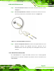


Table Of Contents
- 1 Introduction
- 2 Detailed Specifications
- 3 Unpacking
- 4 Connectors
- 4.1 Peripheral Interface Connectors
- 4.2 Internal Peripheral Connectors
- 4.2.1 BIOS Battery Connector
- 4.2.2 CompactFlash® Socket
- 4.2.3 Digital I/O Connector
- 4.2.4 Fan Connector
- 4.2.5 Front Panel Connector
- 4.2.6 IDE Connector
- 4.2.7 Infrared Interface Connector
- 4.2.8 Keyboard/Mouse Connector
- 4.2.9 LCD Backlight Inverter Connector
- 4.2.10 LED Connector
- 4.2.11 LVDS LCD Connector
- 4.2.12 MCU LAN Connector
- 4.2.13 PCIe Mini Card Slot
- 4.2.14 Power Connectors
- 4.2.15 SATA Drive Connectors
- 4.2.16 SATA Power Connectors
- 4.2.17 Serial Port Connectors (RS-232)
- 4.2.18 Serial Port Connectors (RS-422/485)
- 4.2.19 SO-DIMM Socket
- 4.2.20 SPDIF Connector
- 4.2.21 TV Out Connector
- 4.2.22 USB Connectors
- 4.3 External Peripheral Interface Connector Panel
- 5 Installation
- 6 BIOS Setup
- 7 Software Installation
- 8 Battery Monitoring
- A BIOS Options
- B Terminology
- C Digital I/O Interface
- D Watchdog Timer
- E Address Mapping
- F Hazardous Materials Disclosure
eKINO-945GSE Motherboard
Page 85
Step 1: Locate the dual PS/2 connector. The location of the PS/2 connector is shown
in Chapter 3.
Step 2: Insert the keyboard/mouse connector. Insert the PS/2 connector on the end
of the PS/2 y-cable into the external PS/2 connector. See
Figure 5-13.
Figure 5-13: PS/2 Keyboard/Mouse Connector
Step 3: Connect the keyboard and mouse. Connect the keyboard and mouse to the
appropriate connector. The keyboard and mouse connectors can be
distinguished from each other by looking at the small graphic at the top of the
connector. Step 0:
5.10.3 Serial Device Connection
The eKINO-945GSE has a single female DB-9 connector on the external peripheral
interface panel for a serial device. Follow the steps below to connect a serial device to the
eKINO-945GSE.