EP-308A/EP-308AS POS IEI Technology Corp. MODEL: EP-308A/EP-308AS Mini POS PC with 1.6GHz Intel® Atom CPU, VGA Output, Gigabit Ethernet, USB, RS-232, RS-232/422/485, RoHS Compliant, IP 64 Front Panel User Manual Page i Rev. 1.
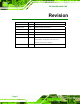
EP-308A/EP-308AS POS Revision Date Version Changes 18 November, 2010 1.14 Added paper jam troubleshooting (Section 2.8.1) 1 October, 2010 1.14 Added EP-308AS specifications 3 September, 2009 1.13 Added more details on installing the paper roll 14 July, 2009 1.12 Added screen resolution warning the front matter 24 June, 2009 1.11 Minor edits 23 June, 2009 1.
EP-308A/EP-308AS POS Copyright COPYRIGHT NOTICE The information in this document is subject to change without prior notice in order to improve reliability, design and function and does not represent a commitment on the part of the manufacturer. In no event will the manufacturer be liable for direct, indirect, special, incidental, or consequential damages arising out of the use or inability to use the product or documentation, even if advised of the possibility of such damages.
EP-308A/EP-308AS POS Table of Contents 1 INTRODUCTION.......................................................................................................... 1 1.1 OVERVIEW.................................................................................................................. 2 1.2 FEATURES ................................................................................................................... 2 1.3 FRONT PANEL .........................................................................
EP-308A/EP-308AS POS 2.9.2.1 Install the Printer Driver ........................................................................... 30 2.9.2.2 Setting the Communication Protocol ........................................................ 36 3 BIOS SETUP ................................................................................................................ 40 3.1 INTRODUCTION......................................................................................................... 41 3.1.
EP-308A/EP-308AS POS 4 SYSTEM MAINTENANCE ....................................................................................... 83 4.1 SYSTEM MAINTENANCE INTRODUCTION .................................................................. 84 4.2 MOTHERBOARD REPLACEMENT ............................................................................... 84 4.3 COVER REMOVAL ..................................................................................................... 84 4.4 MEMORY MODULE REPLACEMENT..........
EP-308A/EP-308AS POS List of Figures Figure 1-1: EP-308A/EP-308AS......................................................................................................2 Figure 1-2: Front Panel ..................................................................................................................3 Figure 1-3: Connectors ..................................................................................................................4 Figure 1-4: Dimensions (units in mm) ..........................
EP-308A/EP-308AS POS Figure 2-27: Print Test Page ........................................................................................................27 Figure 2-28: Printer Installation Complete .................................................................................27 Figure 2-29: Printer Properties....................................................................................................28 Figure 2-30: Configure Printer Port ..........................................................
EP-308A/EP-308AS POS List of Tables Table 1-1: Technical Specifications..............................................................................................5 Table 2-1: Packing List.................................................................................................................10 Table 3-1: BIOS Navigation Keys ................................................................................................
EP-308A/EP-308AS POS BIOS Menus BIOS Menu 1: Main .......................................................................................................................43 BIOS Menu 2: Advanced ..............................................................................................................44 BIOS Menu 3: CPU Configuration ...............................................................................................45 BIOS Menu 4: IDE Configuration.............................................
EP-308A/EP-308AS POS Chapter 1 1 Introduction Page 1
EP-308A/EP-308AS POS 1.1 Overview Figure 1-1: EP-308A/EP-308AS The EP-308A/EP-308AS is a Mini POS with a built-in thermal printer. The EP-308A/EP-308AS has an 8" monitor and a 1.6GHz Intel® Atom processor. Storage needs are met by installing a SATA hard drive or a CompactFlash® card. CompactFlash® cards with Windows CE 6.0, Windows XPE or Linux are also available. Wireless networking is enabled through an optional 802.11b/g wireless adapter.
EP-308A/EP-308AS POS 1.3 Front Panel The front side of the EP-308A/EP-308AS is a flat panel LCD screen surrounded by a frame. Figure 1-2: Front Panel 1.
EP-308A/EP-308AS POS AT/ATX SW Figure 1-3: Connectors 1.5 Technical Specifications The technical specifications for the EP-308A/EP-308AS systems are listed in Table 1-1. SPECIFICATION EP-308A-N270 EP-308AS-N270 Mainboard EPMB-945GSE-R10 v1.2 EPMB-945GSE-R10 v1.3 CPU 1.6GHz Intel® Atom 1.6GHz Intel® Atom LCD Panel 8" 8" Resolution 800 x 600 800 x 600 Brightness 250 nits 250 nits Contrast Ratio 500:1 500:1 LCD Colors 262,000 262,000 Pixel Pitch 0.2025 x 0.2025 0.2025 x 0.
EP-308A/EP-308AS POS SPECIFICATION EP-308A-N270 EP-308AS-N270 I/O 1 x Gigabit LAN 1 x Gigabit LAN 1 x Power input (12 V) 1 x Power input (12 V) 1 x RJ-12 for cash drawer 1 x RJ-12 for cash drawer 1 x RS-232 3 x RS-232 (two internal, 1 x RS-232/422/485 one external) 4 x USB ports 1 x RS-232/422/485 1 x VGA port 4 x USB ports 1 x VGA port Printer 2.0" thermal printer with 2.
EP-308A/EP-308AS POS 1.
EP-308A/EP-308AS POS Chapter 2 2 Installation Page 7
EP-308A/EP-308AS POS WARNING: When installing the EP-308A/EP-308AS, make sure to: Set screen resolution to 800 x 600: To make sure that the touch panel works correctly Turn the power off: Chance of electrocution. Turn off the monitor and unplug it from the power supply. Only let certified engineers change the hardware settings: Incorrect settings can cause irreparable damage to the product. Install the monitor with assistance: The product is very heavy and may be damaged by drops and bumps.
EP-308A/EP-308AS POS WARNING! Only remove the protective plastic cover stuck to the front screen after installation. The plastic layer protects the monitor surface during installation process. Step 1: Carefully cut the tape sealing the box. Only cut deep enough to break the tape. Step 2: Open the outside box. Step 3: Carefully cut the tape sealing the box. Only cut deep enough to break the tape. Step 4: Open the inside box. Step 5: Lift the monitor out of the boxes.
EP-308A/EP-308AS POS Quantity Item 2 RJ-45 to DB-9 cable 1 Utility CD Image Table 2-1: Packing List 2.3 Drive Installation The EP-308A/EP-308AS supports either a SATA hard drive or a CompactFlash® card. To install the hard drive or CompactFlash® card, first open the bottom as shown below, then refer to the individual installation sections. Unfasten the screws to remove the bottom section. Figure 2–1: Opening The System 2.3.
EP-308A/EP-308AS POS Step 1: Slice the hard drive on to connect with the SATA connector. Step 2: Fasten the screws.Step0: Figure 2-2: Aluminum Back Cover Retention Screws 2.3.2 CompactFlash® Installation This section covers the installation of the CompactFlash® card. Step 1: Remove the screw that holds the CompactFlash® card slot cover is place. Step 2: Install the CompactFlash® card in the slot indicated below. Figure 2–3: CompactFlash® Install Step 3: Replace the cover and fasten the screws.
EP-308A/EP-308AS POS 2.4 Mounting the System WARNING! Dropping the EP-308A/EP-308AS can cause irreparable damage. Handle the EP-308A/EP-308AS with care during installation. The following installation options are available: Lift stand Wall arm Wall mount Ceiling mount Mobile mount The installation instructions are included with the stand, arm or mount. 2.
EP-308A/EP-308AS POS 2.5.1 LAN Connection Cable The RJ-45 connectors enable connection to an external network. To connect a LAN cable with an RJ-45 connector, please follow the instructions below. Step 1: Locate the RJ-45 connector on the bottom panel. Step 2: Align the connectors. Align the RJ-45 connector on the LAN cable with one of the RJ-45 connectors on the bottom panel. See Figure 2-5.. Figure 2-5: LAN Connection Step 3: Insert the LAN cable RJ-45 connector.
EP-308A/EP-308AS POS Step 2: Insert the RJ-45 to DB-9 cable. Step 3: Insert the serial connector. Insert the DB-9 connector of a serial device into the DB-9 connector on the cable. See Figure 2-6. Figure 2-6: Serial Device Connector Step 4: Secure the connector. Secure the serial device connector to the external interface by tightening the two retention screws on either side of the connector. Step 0: 2.5.3 USB Device Cable To connect USB devices, please follow the instructions below.
EP-308A/EP-308AS POS Figure 2-7: USB Device Connection Step 3: Insert the device connector. Once aligned, gently insert the USB device connector into the onboard connector. Step 0: 2.5.4 VGA Monitor Connection The EP-308A/EP-308AS has a single female DB-15 connector on the external peripheral interface panel. The DB-15 connector is connected to a CRT or VGA monitor. To connect a monitor to the EP-308A/EP-308AS, please follow the instructions below. Step 1: Locate the female DB-15 connector.
EP-308A/EP-308AS POS Figure 2-8: VGA Connector Step 4: Secure the connector. Secure the DB-15 VGA connector from the VGA monitor to the external interface by tightening the two retention screws on either side of the connector. Step 0: 2.6 Power Connection To connect the power adapter, do the following. Step 1: Connect the power adapter to the EP-308A/EP-308AS. Step 2: Connect the power adapter to the mains power. Step0: 2.
EP-308A/EP-308AS POS The following drivers can be installed on the system, each driver is in its own directory on the driver CD. Install the drivers from each other directories shown.
EP-308A/EP-308AS POS 2.8 Printer Paper Installation To install the roll of paper for the cash register, please follow the steps below. Step 1: Insert the roll of paper as shown below. Figure 2-10: Install Paper Roll Step 2: Make sure the paper is centered.
EP-308A/EP-308AS POS Step 3: The paper should pass through the U-slot as shown below. Figure 2–12: U-slot Alignment Step 4: Push the cover down firmly until it clicks into place. Step0: Figure 2–13: Push Down Firmly 2.8.1 Troubleshooting When paper or cutter jams, do not open the cover with a sharp object. Follow the guide below to troubleshoot: Step 1: Push the cover down firmly until it clicks into place.
EP-308A/EP-308AS POS Figure 2-14: Push the Cover Step 2: Press the EJECT button to open the cover. Figure 2-15: Open the Cover Step 3: If the problem remains, shut down the system. Use a small screwdriver to push the paper cutter back into place then redo Step 1 and Step 2.
EP-308A/EP-308AS POS 2.9 Thermal Printer Setup The EP-308A has a 2.0” thermal printer connected to COM port through USB bridge while the thermal printer of EP-308AS is connected directly through COM port. The following sections describe the thermal printer setup procedures for the EP-308A and the EP-308AS. 2.9.1 EP-308A Thermal Printer Setup The internal printer of the EP-308A is connected to the serial port COMx through USB bridge. To setup the EP-308A thermal printer, please follow the steps below. 2.
EP-308A/EP-308AS POS Step 2: Click NEXT to start the driver installation. Figure 2-18: Installation Wizard Step 3: Click FINISH to complete the installation and exit the installation wizard.
EP-308A/EP-308AS POS 2.9.1.2 Checking Installation To check the installation, look for the USB device shown in the diagram below.
EP-308A/EP-308AS POS 2.9.1.3 Install the Printer Driver Step 1: Extract the driver from "F732". Step 2: Run "Install.exe" Figure 2-21: Printer Installation File Step 3: Click NEXT to start the printer driver installation wizard.
EP-308A/EP-308AS POS Step 4: Select "Local printer attached to this computer" then click NEXT.
EP-308A/EP-308AS POS Step 6: Select "PrnTek-54C" then click NEXT to continue. Figure 2-25: Install Printer Software Step 7: Enter a name for the printer, then click NEXT to continue.
EP-308A/EP-308AS POS Step 8: Choose whether or not to print a test page, then click NEXT to continue. Figure 2-27: Print Test Page Step 9: Click FINISH to complete the driver installation and exit the Installation Wizard.
EP-308A/EP-308AS POS 2.9.1.4 Setting the Communication Protocol Step 1: Right-click the printer icon in "Printers and Faxes", then select "Properties".
EP-308A/EP-308AS POS Step 3: Set the options in Figure 2-31 as shown below. Bits per second: 460800 Data bits: 8 Parity: None Stop bits: 1 Flow control: Xon / Xoff Figure 2-31: Set Communication Options Step 4: Click OK to apply the changes. Step0: WARNING: The thermal printer will be destroyed if pulled, dragged or opened while printing.
EP-308A/EP-308AS POS 2.9.2 EP-308AS Thermal Printer Setup The internal printer of the EP-308AS is connected to the serial port COMx. To setup EP-308AS thermal printer, please follow the steps below. 2.9.2.1 Install the Printer Driver Step 1: Extract the driver from "F732". Step 2: Run "Install.
EP-308A/EP-308AS POS Step 3: Click NEXT to start the printer driver installation wizard. Figure 2-33: Printer Driver Installation Wizard Step 4: Select "Local printer attached to this computer" then click NEXT.
EP-308A/EP-308AS POS Step 5: Select "COM5 (Serial Port)", then click NEXT to continue Figure 2-35: Select Serial Port Step 6: Select "PrnTek-54C" then click NEXT to continue.
EP-308A/EP-308AS POS Step 7: Enter a name for the printer, then click NEXT to continue.
EP-308A/EP-308AS POS Step 8: Select “Replace existing driver”, then click NEXT to continue.
EP-308A/EP-308AS POS Step 9: Choose whether or not to print a test page, then click NEXT to continue. Figure 2-39: Print Test Page Step 10: Click FINISH to complete the driver installation and exit the Installation Wizard.
EP-308A/EP-308AS POS 2.9.2.2 Setting the Communication Protocol Step 1: Access the Printer and Faxes window by clicking “Printer and Faxes” option from the Start menu.
EP-308A/EP-308AS POS Step 2: Right-click the printer icon in "Printers and Faxes", then select "Properties".
EP-308A/EP-308AS POS Step 3: Click Ports tab.
EP-308A/EP-308AS POS Step 4: Set the options in Figure 2-31 as shown below. Bits per second: 115200 Data bits: 8 Parity: None Stop bits: 1 Flow control: Xon / Xoff Figure 2-44: Set Communication Options Step 5: Click OK to apply the changes. Step0: WARNING: The thermal printer will be destroyed if pulled, dragged or opened while printing.
EP-308A/EP-308AS POS Chapter 3 3 BIOS Setup Page 40
EP-308A/EP-308AS POS 3.1 Introduction The BIOS is programmed onto the BIOS chip. The BIOS setup program allows changes to certain system settings. This chapter outlines the options that can be changed. 3.1.1 Starting Setup The AMI BIOS is activated when the computer is turned on. The setup program can be activated in one of two ways. 1. Press the DELETE key as soon as the system is turned on or 2. Press the DELETE key when the “Press Del to enter SETUP” message appears on the screen. 0.
EP-308A/EP-308AS POS Key Function F2 /F3 key Change color from total three colors. F2 to select color forward. F10 key Save all the CMOS changes, only for Main Menu Table 3-1: BIOS Navigation Keys 3.1.3 Getting Help When F1 is pressed a small help window describing the appropriate keys to use and the possible selections for the highlighted item appears. To exit the Help Window press ESC or the F1 key again. 3.1.
EP-308A/EP-308AS POS 3.2 Main The Main BIOS menu (BIOS Menu 1) appears when the BIOS Setup program is entered. The Main menu gives an overview of the basic system information. Main Advanced PCIPNP BIOS SETUP UTILITY Boot Security Chipset System Overview ⎯⎯⎯⎯⎯⎯⎯⎯⎯⎯⎯⎯⎯⎯⎯⎯⎯⎯⎯⎯⎯⎯⎯⎯⎯⎯⎯⎯⎯⎯⎯ AMIBIOS Version :08.00.15 Build Date :12/08/08 ID: :H436MR11 Exit Use [ENTER], [TAB] or [SHIFT-TAB] to select a field. Use [+] or [-] to configure system time. Processor Genuine Intel® CPU N270 @ 1.
EP-308A/EP-308AS POS The System Overview field also has two user configurable fields: System Time [xx:xx:xx] Use the System Time option to set the system time. Manually enter the hours, minutes and seconds. System Date [xx/xx/xx] Use the System Date option to set the system date. Manually enter the day, month and year. 3.
EP-308A/EP-308AS POS 3.3.1 CPU Configuration Use the CPU Configuration menu (BIOS Menu 3) to view detailed CPU specifications and configure the CPU. Main Advanced PCIPNP BIOS SETUP UTILITY Boot Security Chipset Exit Configure Advanced CPU Settings Module Version:3F.12 ⎯⎯⎯⎯⎯⎯⎯⎯⎯⎯⎯⎯⎯⎯⎯⎯⎯⎯⎯⎯⎯⎯⎯⎯⎯⎯⎯⎯⎯⎯⎯ Manufacturer :Intel® Genuine Intel® CPU N270 @ 1.60 GHz Frequency :1.
EP-308A/EP-308AS POS 3.3.2 IDE Configuration Use the IDE Configuration menu (BIOS Menu 4) to change and/or set the configuration of the IDE devices installed in the system.
EP-308A/EP-308AS POS Î Only the IDE drives are enabled. SATA drives are PATA Only disabled Configure SATA as [IDE] Use the Configure SATA as option to configure SATA devices as normal IDE devices. Î IDE Î RAID Used when a RAID setup is installed Î AHCI Enables advanced SATA drive features DEFAULT Configures SATA devices as normal IDE device. 3.3.2.
EP-308A/EP-308AS POS Type: Indicates the type of devices a user can manually select Vendor: Lists the device manufacturer Size: List the storage capacity of the device. LBA Mode: Indicates whether the LBA (Logical Block Addressing) is a method of addressing data on a disk drive is supported or not. Block Mode: Block mode boosts IDE drive performance by increasing the amount of data transferred. Only 512 bytes of data can be transferred per interrupt if block mode is not used.
EP-308A/EP-308AS POS Î This option specifies an ATAPI Removable Media ARMD Device. These include, but are not limited to: ZIP LS-120 LBA/Large Mode [Auto] Use the LBA/Large Mode option to disable or enable BIOS to auto detects LBA (Logical Block Addressing). LBA is a method of addressing data on a disk drive. In LBA mode, the maximum drive capacity is 137 GB. Î BIOS is prevented from using the LBA mode control on Disabled the specified channel.
EP-308A/EP-308AS POS Î Auto DEFAULT BIOS auto detects the PIO mode. Use this value if the IDE disk drive support cannot be determined. Î 0 PIO mode 0 selected with a maximum transfer rate of 3.3 MB/s Î 1 PIO mode 1 selected with a maximum transfer rate of 5.2 MB/s Î 2 PIO mode 2 selected with a maximum transfer rate of 8.3 MB/s Î 3 PIO mode 3 selected with a maximum transfer rate of 11.1 MB/s Î 4 PIO mode 4 selected with a maximum transfer rate of 16.
EP-308A/EP-308AS POS Î Ultra DMA mode 1 selected with a maximum data transfer UDMA1 rate of 25 MB/s Î Ultra DMA mode 2 selected with a maximum data transfer UDMA2 rate of 33.3 MB/s Î Ultra DMA mode 3 selected with a maximum data transfer UDMA3 rate of 44 MB/s (To use this mode, it is required that an 80-conductor ATA cable is used.) Î Ultra DMA mode 4 selected with a maximum data transfer UDMA4 rate of 66.6 MB/s (To use this mode, it is required that an 80-conductor ATA cable is used.
EP-308A/EP-308AS POS 3.3.3 Super IO Configuration Use the Super IO Configuration menu (BIOS Menu 6) to set or change the configurations for the FDD controllers, parallel ports and serial ports.
EP-308A/EP-308AS POS Serial Port3 Address [3E8] Selects the serial port base address. Î Disabled Î 3E8 No base address I/O address 3E8 DEFAULT Î 2E8 I/O address 2E8 Î 2F0 I/O address 2F0 Î 2E0 I/O address 2E0 Serial Port3 IRQ [11] Selects the serial port interrupt address. Î 10 Î 11 IRQ address 10 DEFAULT IRQ address 11 Select RS232 or RS422/RS485 [RS/232] Select the communication method for Serial Port 3.
EP-308A/EP-308AS POS 3.3.4 Hardware Health Configuration The Hardware Health Configuration menu (BIOS Menu 7) shows the operating temperature, fan speeds and system voltages. Main Advanced PCIPNP BIOS SETUP UTILITY Boot Security Chipset Exit Hardware Health Event Monitoring ⎯⎯⎯⎯⎯⎯⎯⎯⎯⎯⎯⎯⎯⎯⎯⎯⎯⎯⎯⎯⎯⎯⎯⎯⎯⎯⎯⎯⎯⎯⎯ CPU FAN Mode Setting [Automatic Mode] CPU Temp. Limit of OFF [000] CPU Temp. Limit of Start [020] CPU_FAN1 Start PWM [070] Slope PWM 1 [0.
EP-308A/EP-308AS POS Î PWM Manual mode The fan spins at the speed set in: Fan PWM control Temp. Limit of OFF [000] WARNING: CPU failure can result if this value is set too high The fan will turn off if the temperature falls below this value. Minimum Value: 0°C Maximum Value: 127°C Temp. Limit of Start [020] WARNING: CPU failure can result if this value is set too high When the fan is off, it will only start when the temperature exceeds this setting.
EP-308A/EP-308AS POS 0 PWM 1 PWM 2 PWM 4 PWM 8 PWM 16 PWM 32 PWM 64 PWM CPU Fan PWM Control [070] This value specifies the speed of the fan. PWM Minimum Mode: 0 PWM Maximum Mode: 127 Monitored Values The following system parameters and values are shown.
EP-308A/EP-308AS POS 3.3.5 Power Configuration The Power Configuration menu (BIOS Menu 8) allows the advanced power management options to be configured. Main Advanced PCIPNP BIOS SETUP UTILITY Boot Security Chipset Exit > ACPI Configuration > APM Configuration ÅÆ ↑ ↓ Enter F1 F10 ESC Select Screen Select Item Go to SubScreen General Help Save and Exit Exit V02.61 ©Copyright 1985-2006, American Megatrends, Inc. BIOS Menu 8: APM Configuration 3.3.5.
EP-308A/EP-308AS POS Suspend Mode [S1(POS)] Use the Suspend Mode option to specify the sleep state the system enters when it is not being used. 3.3.5.2 APM Configuration The APM Configuration menu (BIOS Menu 10) allows the advanced power management options to be configured.
EP-308A/EP-308AS POS Î On/Off DEFAULT When the power button is pressed the system is either turned on or off Î When the power button is pressed the system goes into Suspend suspend mode Resume on Keyboard/Mouse [Disabled] Use the Resume on Keyboard/Mouse BIOS option to enable activity on either the keyboard or mouse to rouse the system from a suspend or standby state. That is, the system is roused when the mouse is moved or a button on the keyboard is pressed.
EP-308A/EP-308AS POS Resume On RTC Alarm [Disabled] Use the Resume On RTC Alarm option to specify the time the system should be roused from a suspended state. Î Disabled DEFAULT The real time clock (RTC) cannot generate a wake event Î If selected, the following appears with values that Enabled can be selected: RTC Alarm Date (Days) System Time After setting the alarm, the computer turns itself on from a suspend state when the alarm goes off. 3.3.
EP-308A/EP-308AS POS Remote Access [Disabled] Use the Remote Access option to enable or disable access to the remote functionalities of the system. Î Disabled Î Enabled DEFAULT Remote access is disabled. Remote access configuration options shown below appear: Serial Port Number Serial Port Mode Flow Control Redirection after BIOS POST Terminal Type VT-UTF8 Combo Key Support These configuration options are discussed below.
EP-308A/EP-308AS POS 115200 8,n,1 57600 8,n,1 38400 8,n,1 19200 8,n,1 09600 8,n,1 DEFAULT NOTE: Identical baud rate setting musts be set on the host (a management computer running a terminal software) and the slave Flow Control [None] Use the Flow Control option to report the flow control method for the console redirection application.
EP-308A/EP-308AS POS Î ANSI Î VT100 The target terminal type is VT100 Î VT-UTF8 The target terminal type is VT-UTF8 DEFAULT The target terminal type is ANSI VT-UTF8 Combo Key Support [Disabled] Use the VT-UFT8 Combo Key Support option to enable additional keys that are not provided by VT100 for the PC 101 keyboard. The VT100 Terminal Definition is the standard convention used to configure and conduct emergency management tasks with UNIX-based servers.
EP-308A/EP-308AS POS 3.3.7 USB Configuration Use the USB Configuration menu (BIOS Menu 12) to read USB configuration information and configure the USB settings. Main Advanced PCIPNP BIOS SETUP UTILITY Boot Security Chipset USB Configuration ⎯⎯⎯⎯⎯⎯⎯⎯⎯⎯⎯⎯⎯⎯⎯⎯⎯⎯⎯⎯⎯⎯⎯⎯⎯⎯⎯⎯⎯⎯⎯ Module Version – 2.24.0-11.4 Exit Options Disabled Enabled USB Devices Enabled: 1 Keyboard, 1 Mouse USB Function USB 2.0 Controller Legacy USB Support USB 2.
EP-308A/EP-308AS POS USB 2.0 Controller [Enabled] Use the USB 2.0 Controller BIOS option to enable or disable the USB 2.0 controller Î Disabled Î Enabled USB 2.0 controller disabled DEFAULT USB 2.0 controller enabled Legacy USB Support [Enabled] Use the Legacy USB Support BIOS option to enable USB mouse and USB keyboard support.
EP-308A/EP-308AS POS 3.3.7.1 USB Mass Storage Device Configuration Use the USB Mass Storage Device Configuration menu (BIOS Menu 13) to configure USB mass storage class devices. Main Advanced PCIPNP BIOS SETUP UTILITY Boot Security Chipset Exit USB Mass Storage Device Configuration ⎯⎯⎯⎯⎯⎯⎯⎯⎯⎯⎯⎯⎯⎯⎯⎯⎯⎯⎯⎯⎯⎯⎯⎯⎯⎯⎯⎯⎯⎯⎯ USB Mass Storage Reset Delay [20 Sec] Device #1 Emulation Type M-SysT5 Dell Memory Key 5.
EP-308A/EP-308AS POS Emulation Type [Auto] Use the Emulation Type BIOS option to specify the type of emulation BIOS has to provide for the USB device. Î Auto Î Floppy DEFAULT BIOS auto-detects the current USB. The USB device will be emulated as a floppy drive. The device can be either A: or B: responding to INT13h calls that return DL = 0 or DL = 1 respectively. Î Forced FDD Allows a hard disk image to be connected as a floppy image.
EP-308A/EP-308AS POS Main Advanced PCIPNP BIOS SETUP UTILITY Boot Security Chipset Advanced PCI/PnP Settings ⎯⎯⎯⎯⎯⎯⎯⎯⎯⎯⎯⎯⎯⎯⎯⎯⎯⎯⎯⎯⎯⎯⎯⎯⎯⎯⎯⎯⎯⎯⎯ IRQ3 [Reserved] IRQ4 [Reserved] IRQ5 [Available] IRQ7 [Available] IRQ9 [Available] IRQ10 [Reserved] IRQ11 [Reserved] IRQ14 [Available] IRQ15 [Available] DMA DMA DMA DMA DMA DMA Channel Channel Channel Channel Channel Channel 0 1 3 5 6 7 [Available] [Available] [Available] [Available] [Available] [Available] Reserved Memory Size [Disabled] Exit Available: S
EP-308A/EP-308AS POS IRQ10 IRQ 11 IRQ 14 IRQ 15 DMA Channel# [Available] Use the DMA Channel# option to assign a specific DMA channel to a particular PCI/PnP device.
EP-308A/EP-308AS POS 3.5 Boot Use the Boot menu (BIOS Menu 15) to configure system boot options. Main Advanced PCIPNP BIOS SETUP UTILITY Boot Security Chipset Boot Settings ⎯⎯⎯⎯⎯⎯⎯⎯⎯⎯⎯⎯⎯⎯⎯⎯⎯⎯⎯⎯⎯⎯⎯⎯⎯⎯⎯⎯⎯⎯⎯ > Boot Settings Configuration > > > > Boot Device Priority Hard Disk Drives CD/DVD Drives Removable Drives Exit Configure settings during system boot. ÅÆ ↑ ↓ Enter F1 F10 ESC Select Screen Select Item Go to SubScreen General Help Save and Exit Exit v02.
EP-308A/EP-308AS POS Quick Boot [Enabled] Use the Quick Boot BIOS option to make the computer speed up the boot process. Î Disabled Î Enabled No POST procedures are skipped DEFAULT Some POST procedures are skipped to decrease the system boot time Quiet Boot [Enabled] Use the Quiet Boot BIOS option to select the screen display when the system boots.
EP-308A/EP-308AS POS Î On DEFAULT Allows the Number Lock on the keyboard to be enabled automatically when the computer system boots up. This allows the immediate use of the 10-key numeric keypad located on the right side of the keyboard. To confirm this, the Number Lock LED light on the keyboard is lit. Boot From LAN Support [Disabled] Use the BOOT From LAN Support option to enable the system to be booted from a remote system.
EP-308A/EP-308AS POS 3.5.2 Boot Device Priority Use the Boot Device Priority menu (BIOS Menu 17) to specify the boot sequence from the available devices. The drive sequence also depends on the boot sequence in the individual device section.
EP-308A/EP-308AS POS 3.5.3 Hard Disk Drives Use the Hard Disk Drives menu to specify the boot sequence of the available HDDs. Only installed hard drives are shown. Main Advanced PCIPNP BIOS SETUP UTILITY Boot Security Chipset Hard Disk Drives ⎯⎯⎯⎯⎯⎯⎯⎯⎯⎯⎯⎯⎯⎯⎯⎯⎯⎯⎯⎯⎯⎯⎯⎯⎯⎯⎯⎯⎯⎯⎯ > 1st Drive [Hard Drive 1] > 2nd Drive [Hard Drive 2] > 3rd Drive [Hard Drive 3] Exit Specifies the boot sequence from the available devices.
EP-308A/EP-308AS POS 3.5.5 CD/DVD Drives Use the CD/DVD Drives menu to specify the boot sequence of the available CD/DVD drives. When the menu is opened, the CD drives and DVD drives connected to the system are listed as shown below: 1st Drive [CD/DVD: PM-(part ID)] 2nd Drive [HDD: PS-(part ID)] 3rd Drive [HDD: SM-(part ID)] 4th Drive [HDD: SM-(part ID)] NOTE: Only the drives connected to the system are shown.
EP-308A/EP-308AS POS 3.6 Security Use the Security menu (BIOS Menu 21) to set system and user passwords. Main Advanced PCIPNP BIOS SETUP UTILITY Boot Security Chipset Exit Security Settings ⎯⎯⎯⎯⎯⎯⎯⎯⎯⎯⎯⎯⎯⎯⎯⎯⎯⎯⎯⎯⎯⎯⎯⎯⎯⎯⎯⎯⎯⎯⎯ Supervisor Password :Not Installed User Password :Not Installed Change Supervisor Password Change User Password ÅÆ ↑ ↓ Enter F1 F10 ESC Select Screen Select Item Go to SubScreen General Help Save and Exit Exit v02.61 ©Copyright 1985-2006, American Megatrends, Inc.
EP-308A/EP-308AS POS 3.7 Chipset Use the Chipset menu (BIOS Menu 22) to access the Northbridge and Southbridge configuration menus WARNING! Setting the wrong values for the Chipset BIOS selections in the Chipset BIOS menu may cause the system to malfunction.
EP-308A/EP-308AS POS 3.7.1 Northbridge Configuration Use the Northbridge Chipset Configuration menu (BIOS Menu 23) to configure the Northbridge chipset. Main Advanced PCIPNP BIOS SETUP UTILITY Boot Security Chipset Exit Northbridge Configuration ⎯⎯⎯⎯⎯⎯⎯⎯⎯⎯⎯⎯⎯⎯⎯⎯⎯⎯⎯⎯⎯⎯⎯⎯⎯⎯⎯⎯⎯⎯⎯ Memory Hole [Disabled] Internal Graphics Mode Select [Enabled, 8MB] Video Function Configuration ⎯⎯⎯⎯⎯⎯⎯⎯⎯⎯⎯⎯⎯⎯⎯⎯⎯⎯⎯⎯⎯⎯⎯⎯⎯⎯⎯⎯⎯⎯⎯ DVMT Mode Select [DVMT Mode] DVMT/FIXED Memory [128MB] Boot Display Device Sec.
EP-308A/EP-308AS POS Î Enable, 1 MB Î Enable, 8 MB Dedicates 1 MB of main memory for graphics DEFAULT Dedicated 8 MB of main memory for graphics DVMT Mode Select [DVMT Mode] Use the DVMT Mode Select option to select the Intel Dynamic Video Memory Technology (DVMT) operating mode. Î A fixed portion of graphics memory is reserved as Fixed Mode graphics memory. Î DVMT Mode DEFAULT Graphics memory is dynamically allocated according to the system and graphics needs.
EP-308A/EP-308AS POS LVDS Panel Type Use the Panel Type to determine the LCD panel resolution. Configuration options are listed below: 1024x768 24b 1280x1024 48b 1366x768 24b 1440x900 48b BY HARDWARE DEFAULT Current Jumper Setting Shows current value of the hardware jumper setting for the LVDS resolution. This is the value used when "BY HARDWARE" is selected in the setting above. 3.7.
EP-308A/EP-308AS POS Cashdraw Control [Enabled] Use the Cashdraw Control option to enable or disable the port that controls the cashdraw. Enabled Disabled DEFAULT Audio Controller [Auto] Use the HDA Controller option to enable or disable High Definition audio codec. Î Auto Î Azalia Enabled High Definition audio Î AC'97 Audio Only Enable AC'97 audio Î All disabled No audio DEFAULT 3.
EP-308A/EP-308AS POS Save Changes and Exit Use the Save Changes and Exit option to save the changes made to the BIOS options and to exit the BIOS configuration setup program. Discard Changes and Exit Use the Discard Changes and Exit option to exit the BIOS configuration setup program without saving the changes made to the system. Discard Changes Use the Discard Changes option to discard the changes and remain in the BIOS configuration setup program.
EP-308A/EP-308AS POS Chapter 4 4 System Maintenance Page 83
EP-308A/EP-308AS POS 4.1 System Maintenance Introduction If the components of the EP-308A/EP-308AS fail they must be replaced, such as the wireless LAN module or the motherboard. Please contact the system reseller or vendor to purchase the replacement parts. Back cover removal instructions and jumper settings for the EP-308A/EP-308AS are described below. 4.2 Motherboard Replacement In the case of motherboard failure, please contact an IEI sales representative, reseller or system vendor.
EP-308A/EP-308AS POS Figure 4-1: Bottom Cover Retention Screws 4.4 Memory Module Replacement The flat panel PC has a preinstalled memory module. If the memory module fails, take the steps below to replace it. Step 1: Remove the back cover. See Section 4.3 above. Step 2: Locate the memory module on the motherboard of the flat panel PC Step 3: Remove the memory module by pulling both the spring retainer clips outward from the socket.
EP-308A/EP-308AS POS Figure 4-2: DDR SO-DIMM Module Installation 4.5 Hard Drive and CompactFlash® Replacement To replace the hard drive or CompactFlash® card, please refer to the hard drive and CompactFlash® installation sections.
EP-308A/EP-308AS POS Appendix A A Safety Precautions Page 87
EP-308A/EP-308AS POS WARNING: The precautions outlined in this chapter should be strictly followed. Failure to follow these precautions may result in permanent damage to the EP-308A/EP-308AS. A.1 Safety Precautions Please follow the safety precautions outlined in the sections that follow: A.1.1 General Safety Precautions Please ensure the following safety precautions are adhered to at all times. Follow the electrostatic precautions outlined below whenever the EP-308A/EP-308AS is opened.
EP-308A/EP-308AS POS A.1.2 Anti-static Precautions WARNING: Failure to take ESD precautions during the installation of the EP-308A/EP-308AS may result in permanent damage to the EP-308A/EP-308AS and sever injury to the user. Electrostatic discharge (ESD) can cause serious damage to electronic components, including the EP-308A/EP-308AS. Dry climates are especially susceptible to ESD.
EP-308A/EP-308AS POS Except for the LCD panel, never spray or squirt liquids directly onto any other components. To clean the LCD panel, gently wipe it with a piece of soft dry cloth or a slightly moistened cloth. The interior does not require cleaning. Keep fluids away from the interior. Be careful not to damage the small, removable components inside. Turn off before cleaning. Never drop any objects or liquids through the openings.
EP-308A/EP-308AS POS Appendix B B BIOS Options Page 91
EP-308A/EP-308AS POS Below is a list of BIOS configuration options in the BIOS chapter. System Overview .................................................................................................................43 System Time [xx:xx:xx] .......................................................................................................44 System Date [xx/xx/xx] ........................................................................................................
EP-308A/EP-308AS POS Remote Access [Disabled]..................................................................................................61 Serial Port Number [COM1].................................................................................................61 Base Address, IRQ [2F8h,3]................................................................................................61 Serial Port Mode [115200 8,n,1].....................................................................................
EP-308A/EP-308AS POS Current Jumper Setting.......................................................................................................80 Cashdraw Control [Enabled]...............................................................................................81 Audio Controller [Auto] .......................................................................................................81 Save Changes and Exit .......................................................................................
EP-308A/EP-308AS POS Appendix C C Terminology Page 95
EP-308A/EP-308AS POS AC ’97 Audio Codec 97 (AC’97) refers to a codec standard developed by Intel® in 1997. ACPI Advanced Configuration and Power Interface (ACPI) is an OS-directed configuration, power management, and thermal management interface. AHCI Advanced Host Controller Interface (AHCI) is a SATA Host controller register-level interface. ATA The Advanced Technology Attachment (ATA) interface connects storage devices including hard disks and CD-ROM drives to a computer.
EP-308A/EP-308AS POS EIDE Enhanced IDE (EIDE) is a newer IDE interface standard that has data transfer rates between 4.0 MBps and 16.6 MBps. EIST Enhanced Intel® SpeedStep Technology (EIST) allows users to modify the power consumption levels and processor performance through application software. The application software changes the bus-to-core frequency ratio and the processor core voltage.
EP-308A/EP-308AS POS SATA Serial ATA (SATA) is a serial communications bus designed for data transfers between storage devices and the computer chipsets. The SATA bus has transfer speeds up to 1.5 Gbps and the SATA II bus has data transfer speeds of up to 3.0 Gbps. S.M.A.R.T Self Monitoring Analysis and Reporting Technology (S.M.A.R.T) refers to automatic status checking technology implemented on hard disk drives.
EP-308A/EP-308AS POS Appendix D D Watchdog Timer Page 99
EP-308A/EP-308AS POS NOTE: The following discussion applies to DOS environment. IEI support is contacted or the IEI website visited for specific drivers for more sophisticated operating systems, e.g., Windows and Linux. The Watchdog Timer is provided to ensure that standalone systems can always recover from catastrophic conditions that cause the CPU to crash. This condition may have occurred by external EMIs or a software bug.
EP-308A/EP-308AS POS NOTE: When exiting a program it is necessary to disable the Watchdog Timer, otherwise the system resets.
EP-308A/EP-308AS POS Appendix E E Hazardous Materials Disclosure Page 102
EP-308A/EP-308AS POS E.1 Hazardous Materials Disclosure Table for IPB Products Certified as RoHS Compliant Under 2002/95/EC Without Mercury The details provided in this appendix are to ensure that the product is compliant with the Peoples Republic of China (China) RoHS standards. The table below acknowledges the presences of small quantities of certain materials in the product, and is applicable to China RoHS only.
EP-308A/EP-308AS POS Part Name Toxic or Hazardous Substances and Elements Lead Mercury Cadmium Hexavalent Polybrominated Polybrominated (Pb) (Hg) (Cd) Chromium Biphenyls Diphenyl Ethers (CR(VI)) (PBB) (PBDE) Housing X O O O O X Display X O O O O X Printed Circuit X O O O O X Metal Fasteners X O O O O O Cable Assembly X O O O O X Fan Assembly X O O O O X Power Supply X O O O O X O O O O O O Board Assemblies Battery O: This toxic or haza
EP-308A/EP-308AS POS 此附件旨在确保本产品符合中国 RoHS 标准。以下表格标示此产品中某有毒物质的含量符 合中国 RoHS 标准规定的限量要求。 本产品上会附有”环境友好使用期限”的标签,此期限是估算这些物质”不会有泄漏或突变”的 年限。本产品可能包含有较短的环境友好使用期限的可替换元件,像是电池或灯管,这些元 件将会单独标示出来。 部件名称 有毒有害物质或元素 铅 汞 镉 六价铬 多溴联苯 多溴二苯醚 (Pb) (Hg) (Cd) (CR(VI)) (PBB) (PBDE) 壳体 X O O O O X 显示 X O O O O X 印刷电路板 X O O O O X 金属螺帽 X O O O O O 电缆组装 X O O O O X 风扇组装 X O O O O X 电力供应组装 X O O O O X 电池 O O O O O O O: 表示该有毒有害物质在该部件所有物质材料中的含量均在 SJ/T11363-2006 标准规定的限量要求以下。