
Instruction Manual


IMB-Q670 Micro-ATX Motherboard
Page 19
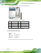
Figure 3-2: ATX/AT Power Connector Pinout Location
Pin Description Pin Description
1 +3.3V 13 +3.3V
2 +3.3V 14 -12V
3 GND 15 GND
4 +5V 16 IO_PS_ON#
5 GND 17 GND
6 +5V 18 GND
7 GND 19 GND
8 PWRGD_PS 20 NC
9 +5VSB1 21 +5V
10 +12V 22 +5V
11 +12V 23 +5V
12 +3.3V 24 GND
Table 3-3: ATX/AT Power Connector Pinouts