
Instruction Manual


IMB-Q670 Micro-ATX Motherboard
Page 44
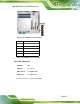
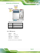
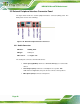
3.3.3 Ethernet and USB Connector
CN Label: LAN1_USB, LAN2_USB
CN Type:
RJ-45, USB
CN Location:
See Figure 3-24
CN Pinouts:
See Table 3-26, Table 3-28 and Table 3-29
Each LAN connector connects to a local network.
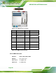
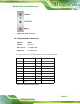
Pin Description Pin Description
1 MDIA3- 5 MDIA2+
2 MDIA3+ 6 MDIA1+
3 MDIA1- 7 MDIA0-
4 MDIA2- 8 MDIA0+
Table 3-26: LAN Pinouts
Figure 3-26: Ethernet Connector
LED Description LED Description
A on: linked
blinking: data is being sent/received
B off: 10 Mb/s
green: 100 Mb/s
orange: 1000 Mb/s
Table 3-27: Ethernet Connector LEDs
The USB connector can be connected to a USB device.
PIN DESCRIPTION PIN DESCRIPTION
1 USBPWR1/2 2 USB20_C_N0
3 USB20_C_P0 4 GND