IMBA-9454G Motherboard IEI Technology Corp. MODEL: IMBA-9454G ATX SBC Supports Intel® LGA775 Core 2 Duo™ Intel® Pentium™ 4/D, Intel® Celeron™ D, FSB 533/800/1066 MHz PCIe x16, PCIe GbE, USB 2.0, SATA II, Audio, RoHS User Manual Page i Rev. 4.02 1.
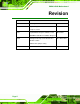
IMBA-9454G Motherboard Revision MODEL IMBA-9454G Motherboard Revision Number Description 4.02 Updated Figure 5-11: COM2 Mode Selection November 2011 Date of Issue Jumper Location 4.01 Updated BIOS Chapter 6 to BIOS version March 2011 B188MR14 and Driver Installation Chapter 7 4.00 Changed LAN chipset from Broadcom to December 2010 Realtek solution Added JSPI1 jumper setting 1.
IMBA-9454G Motherboard Copyright COPYRIGHT NOTICE The information in this document is subject to change without prior notice in order to improve reliability, design and function and does not represent a commitment on the part of the manufacturer. In no event will the manufacturer be liable for direct, indirect, special, incidental, or consequential damages arising out of the use or inability to use the product or documentation, even if advised of the possibility of such damages.
IMBA-9454G Motherboard Packing List NOTE: If any of the components listed in the checklist below are missing, please do not proceed with the installation. Contact the IEI reseller or vendor you purchased the IMBA-9454G motherboard from or contact an IEI sales representative directly. To contact an IEI sales representative, please send an email to sales@iei.com.tw. The items listed below should all be included in the IMBA-9454G motherboard package.
IMBA-9454G Motherboard Table of Contents 1 INTRODUCTION.......................................................................................................... 2 1.1 OVERVIEW.................................................................................................................. 3 1.1.1 Features ............................................................................................................. 3 1.1.2 Connectors ..........................................................................
IMBA-9454G Motherboard 2.7.1 PCI Bus Overview............................................................................................ 20 2.7.2 Realtek LAN interface ...................................................................................... 20 2.7.3 BIOS Chipset.................................................................................................... 20 2.7.4 Super I/O chipset.............................................................................................. 21 2.7.4.
IMBA-9454G Motherboard 4.2.7 Digital Input/Output (DIO) Connector............................................................ 41 4.2.8 Fan Connectors................................................................................................ 42 4.2.9 Floppy Disk Connector .................................................................................... 43 4.2.10 Front Panel Audio Connector........................................................................ 45 4.2.11 IDE Connector (40-pin) .......
IMBA-9454G Motherboard 5.3.3 DIMM Installation ........................................................................................... 82 5.4 JUMPER SETTINGS .................................................................................................... 83 5.4.1 CF Master/Slave Selection............................................................................... 84 5.4.2 Clear CMOS Jumper........................................................................................ 84 5.4.
IMBA-9454G Motherboard 6.3.4 Super IO Configuration ..................................................................................112 6.3.5 Hardware Health Configuration.....................................................................117 6.3.6 Power Configuration.......................................................................................119 6.3.6.1 ACPI Configuration .................................................................................119 6.3.6.2 APM Configuration.............
IMBA-9454G Motherboard C.2 1ST MB MEMORY ADDRESS MAP .......................................................................... 172 C.3 IRQ MAPPING TABLE ............................................................................................ 173 C.4 DMA CHANNEL ASSIGNMENTS ............................................................................. 173 D EXTERNAL AC’97 AUDIO CODEC ..................................................................... 174 D.1 INTRODUCTION ...............................
IMBA-9454G Motherboard List of Figures Figure 1-1: IMBA-9454G .................................................................................................................3 Figure 1-2: IMBA-9454G Connectors ............................................................................................5 Figure 2-1: IMBA-9454G Dimensions (mm)................................................................................11 Figure 2-2: External Interface Panel Dimensions (mm) ................................
IMBA-9454G Motherboard Figure 4-26: PS/2 Pinouts ............................................................................................................64 Figure 4-27: Parallel Port Connector Pinout Locations............................................................65 Figure 4-28: Ethernet Connector Pinout Locations ..................................................................66 Figure 4-29: Ethernet Connector.......................................................................................
IMBA-9454G Motherboard Figure 7-5: Chipset Driver Installation License Agreement .................................................. 148 Figure 7-6: Chipset Driver Readme File Information ............................................................. 149 Figure 7-7: Chipset Driver Installation Complete ................................................................... 149 Figure 7-8: VGA Driver ..............................................................................................................
IMBA-9454G Motherboard List of Tables Table 1-1: Technical Specifications..............................................................................................8 Table 2-1: Supported Intel® Core™ 2 Duo Processors ............................................................14 Table 2-2: Supported Intel® Pentium® 4 Processors ...............................................................14 Table 2-3: Supported Intel® Pentium® D Processors ..............................................................
IMBA-9454G Motherboard Table 4-23: Serial Port Connector (RS-422/485) Pinouts..........................................................60 Table 4-24: SPDIF Connector Pinouts ........................................................................................61 Table 4-25: TPM Connector Pinouts ...........................................................................................62 Table 4-26: USB Port Connector Pinouts.................................................................................
IMBA-9454G Motherboard List of BIOS Menus BIOS Menu 1: Main .................................................................................................................... 103 BIOS Menu 2: Advanced ........................................................................................................... 105 BIOS Menu 3: CPU Configuration ............................................................................................ 105 BIOS Menu 4: IDE Configuration......................................
IMBA-9454G Motherboard Glossary Page xvii
IMBA-9454G Motherboard AC’97 Audio Codec 97 HDD Hard Disk Drive ACPI Advanced Configuration and IDE Integrated Data Electronics Power Interface I/O Input/Output APM Advanced Power Management ICH4 I/O Controller Hub 4 ARMD ATAPI Removable Media Device L1 Cache Level 1 Cache ASKIR Shift Keyed Infrared L2 Cache Level 2 Cache ATA Advanced Technology LCD Liquid Crystal Display Attachments LPT Parallel Port Connector BIOS Basic Input/Output System LVDS Low Voltage Differential CFII
IMBA-9454G Motherboard Chapter 1 1 Introduction Page 2
IMBA-9454G Motherboard 1.1 Overview Figure 1-1: IMBA-9454G The IMBA-9454G motherboard is an LGA775 Intel® Core™ 2 Duo/Intel® Pentium® 4/Intel® Pentium® D/Intel® Celeron® D CPU platform with an Intel® 945G Express Chipset and Intel® I/O Controller Hub 7 (ICH7) Southbridge.
IMBA-9454G Motherboard o LGA775 Intel® Celeron® D Integrated Intel® GMA950 graphics engine Maximum FSB of 1066MHz Four 240-pin dual channel 400/533/677MHz DDR2 SDRAM DIMMs support up to 4GB of memory High performance PCIe Gigabit Ethernet chipset (LAN1 with ASF2.0 remote control support) Four SATA 3Gb/s drives supported Two Ultra ATA 100, Ultra ATA 66 or Ultra ATA 33 IDE HDDs supported Eight USB 2.0 devices supported ATX power only 5.
IMBA-9454G Motherboard 1.1.2 Connectors The IMBA-9454G has a wide variety of internal and external peripheral connectors. The peripheral connectors are connected to devices including storage devices, display devices and parallel communications devices. A labeled photo of the peripheral connectors is shown in Figure 1-2. Figure 1-2: IMBA-9454G Connectors The IMBA-9454G has the following on-board connectors: 1 x 12V power connector 1 x ATX power connector 1 x Audio connector 1 x Aux.
IMBA-9454G Motherboard 1 x CD-in connector 1 x CompactFlash slot 4 x DDR2 DIMM slots 1 x DIO connector 3 x Fan connectors 1 x Floppy disk connector 1 x IDE disk drive connector 1 x Infrared interface connector 1 x Multi panel connector 1 x PCIe slot 6 x PCI slots 4 x Serial ATA (SATA) drive connectors 6 x Serial port connectors 1 x SPDIF connector 1 x TPM connector 2 x USB connectors The IMBA-9454G has the following external peripheral interfac
IMBA-9454G Motherboard 1.1.3 Technical Specifications IMBA-9454G technical specifications are listed in Table 1-1. Detailed descriptions of each specification can be found in Chapter 2. Specification Form Factor IMBA-9454G ATX motherboard LGA775 Intel® Core™ 2 Duo (up to 2.66GHz) LGA775 Intel® Pentium® 4 (up to 3.8GHz) System CPU LGA775 Intel® Pentium® D (up to 3.6GHz) LGA775 Intel® Celeron® D (up to 3.
IMBA-9454G Motherboard Specification IMBA-9454G Six on-board serial ports: COM Four on-board RS-232 serial ports One on-board RS-232/422/485 serial port (by jumper setting) One on-board RS-422/485 serial port (by jumper setting) USB 2.0 Eight USB 2.
IMBA-9454G Motherboard Chapter 2 2 Detailed Specifications Page 9
IMBA-9454G Motherboard Page 10
IMBA-9454G Motherboard 2.1 Overview This chapter describes the specifications and on-board features of the IMBA-9454G in detail. 2.2 Dimensions 2.2.1 Board Dimensions The dimensions of the board are listed below and shown in Figure 2-1.
IMBA-9454G Motherboard 2.2.2 External Interface Panel Dimensions External peripheral interface connector panel dimensions are shown in Figure 2-2.
IMBA-9454G Motherboard 2.3 Data Flow Figure 2-3 shows the data flow between the two on-board chipsets and other components installed on the motherboard and described in the following sections of this chapter. Figure 2-3: Data Flow Block Diagram 2.4 Compatible Processors 2.4.1 CPU Overview LGA775 Intel® Core™ 2 Duo, Intel® Pentium® 4, Intel® Pentium® D and Intel® Celeron® D processors can be installed on the IMBA-9454G motherboard.
IMBA-9454G Motherboard 2.4.2 Supported Intel® Core™ 2 Duo Processors Specifications for the compatible Intel® Core™ 2 Duo processors are listed in Table 2-1. CPU Speed Bus Speed Mfg. Tech Cache Package Processor No. 2.66 GHz 1066 MHz 65 nm 4 MB LGA775 E6700 2.40 GHz 1066 MHz 65 nm 4 MB LGA775 E6600 2.13 GHz 1066 MHz 65 nm 2 MB LGA775 E6400 1.86 GHz 1066 MHz 65 nm 2 MB LGA775 E6300 1.
IMBA-9454G Motherboard 2.4.4 Supported Intel® Pentium® D Processors Specifications for the compatible Intel® Pentium® D processors are listed in Table 2-3. CPU Speed Bus Speed Mfg. Tech Cache Package Processor No. 3.60 GHz 800 MHz 65 nm 4 MB LGA775 960 3.40 GHz 800 MHz 65 nm 4 MB LGA775 950 3.40 GHz 800 MHz 65 nm 4 MB LGA775 945 Table 2-3: Supported Intel® Pentium® D Processors 2.4.
IMBA-9454G Motherboard Supports four, 1GB, 400/533/667MHz dual channel DDR SDRAM DIMMs Integrated VGA and SDVO (Serial Digital Video Output) outputs Integrated Intel® Graphics Media Accelerator 950 (Intel® GMA 950) 2.
IMBA-9454G Motherboard o Up to 10.6 GB/sec memory bandwidth with DDR2 667 MHz system memory o o o o o 1.6 GPixels/sec and 1.
IMBA-9454G Motherboard Integrated IDE controller supports Ultra ATA 100/66/33 Supports eight USB 2.0 devices with four UHCI controllers and one EHCI controller Complies with System Management Bus (SMBus) Specification, Version 2.0 Supports Audio Codec ’97 (AC’97) Revision 2.3 Serial Peripheral Interface (SPI) for Serial and Shared Flash 1.05 V Core Voltage 2.6.2 Realtek ALC655 Audio Codec ’97 Controller The ALC655 complies with AC’97 Component Specification, Version 2.3.
IMBA-9454G Motherboard Specification PIO Max Transfer Rate DMA/UDMA designation Ultra ATA/100 Ultra ATA/66 Ultra ATA/33 16.6 MB/s 16.6 MB/s 16.6 MB/s UDMA 3 - 4 UDMA 3 – 4 UDMA 2 100MB/s 66MB/s 33MB/s 5V 5V 5V DMA/UDMA Max Transfer Controller Interface Table 2-5: Supported HDD Specifications 2.6.4 Intel® ICH7 PCI Interface The PCI interface on the ICH7 is compliant with the PCI Revision 2.3 implementation. Some of the features of the PCI interface are listed below. PCI Revision 2.
IMBA-9454G Motherboard 2.6.7 Intel® ICH7 USB Controller Up to eight high-speed, full-speed or low-speed USB devices are supported by the ICH7. High-speed USB 2.0, with data transfers of up to 480MB/s, is enabled with the ICH7 integrated Enhanced Host Controller Interface (EHCI) compliant host controller. USB full-speed and low-speed signaling is supported by the four ICH7 integrated Universal Host Controller Interface (UHCI) controller. 2.7 PCI Bus Components 2.7.
IMBA-9454G Motherboard Console redirection function support PXE (Pre-boot Execution Environment) support USB booting support 2.7.4 Super I/O chipset The iTE IT8712F Super I/O chipset is connected to the ICH6 southbridge through the LPC bus. The iTE IT8712F is an LPC interface-based Super I/O device that comes with Environment Controller integration.
IMBA-9454G Motherboard Two standard serial ports (COM1 and COM2) IrDa 1.0 and ASKIR protocols Another two chipsets connected to the LPC bus provided connectivity to another two serial port connectors (COM3 and COM4). 2.7.4.3 Super I/O Enhanced Hardware Monitor The Super I/O Enhanced Hardware Monitor monitors three thermal inputs, VBAT internally, and eight voltage monitor inputs. These hardware parameters are reported in the BIOS and can be read from the BIOS Hardware Health Configuration menu. 2.
IMBA-9454G Motherboard Gate A20 and Keyboard reset output Supports multiple keyboard power on events Supports mouse double-click and/or mouse move power on events 2.8 Environmental and Power Specifications 2.8.
IMBA-9454G Motherboard The values for the above environmental parameters are all recorded in the BIOS Hardware Health Configuration menu. 2.8.2 Operating Temperature and Temperature Control The maximum and minimum operating temperatures for the IMBA-9454G are listed below. Minimum Operating Temperature: 0ºC (32°F) Maximum Operating Temperature: 60°C (140°F) A cooling fan and heat sink must be installed on the CPU.
IMBA-9454G Motherboard Chapter 3 3 Unpacking Page 25
IMBA-9454G Motherboard Page 26
IMBA-9454G Motherboard 3.1 Anti-static Precautions WARNING: Failure to take ESD precautions during the installation of the IMBA-9454G may result in permanent damage to the IMBA-9454G and severe injury to the user. Electrostatic discharge (ESD) can cause serious damage to electronic components, including the IMBA-9454G. Dry climates are especially susceptible to ESD.
IMBA-9454G Motherboard 3.2 Unpacking 3.2.1 Unpacking Precautions When the IMBA-9454G is unpacked, please do the following: Follow the anti-static precautions outlined in Section 3.1. Make sure the packing box is facing upwards so the IMBA-9454G does not fall out of the box. Make sure all the components shown in Section 3.3 are present. 3.3 Unpacking Checklist NOTE: If any components listed in the checklist below are missing, do not proceed with the installation.
IMBA-9454G Motherboard Quantity Item and Part Number Image Dual RS-232 cable 2 (P/N: 19800-000113-RS) SATA cables 2 (P/N: 32000-0628000-RS) SATA power cable 1 (P/N: 32102-000100-100/200-RS) I/O Shielding 1 (P/N: 45014-0017C0-00-RS) Mini jumper Pack 1 (P/N: 33100-000079-RS) Quick Installation Guide 1 (P/N: 51000-001083-RS) Utility CD 1 (P/N: IEI-7B000-000096-RS) Table 3-1: Package List Contents Page 29
IMBA-9454G Motherboard 3.3.2 Optional Components The following optional components are available from IEI.
IMBA-9454G Motherboard Chapter 4 4 Connector Pinouts Page 31
IMBA-9454G Motherboard Page 32
IMBA-9454G Motherboard 4.1 Peripheral Interface Connectors Section 4.1.1 shows peripheral interface connector locations. Section 4.1.2 lists all the peripheral interface connectors seen in Section 4.1.1. 4.1.1 IMBA-9454G Layout Figure 4-1 shows the on-board peripheral connectors, rear panel peripheral connectors and on-board jumpers. Figure 4-1: Connector and Jumper Locations 4.1.2 Peripheral Interface Connectors Table 4-1 shows a list of the peripheral interface connectors on the IMBA-9454G.
IMBA-9454G Motherboard Connector Type Label CompactFlash connector 50-pin CF slot CF1 Digital input/output connector 10-pin header DIO1 Fan connector - CPU 4-pin wafer FAN1 Fan connector - System 3-pin wafer FAN2 Fan connector - System 3-pin wafer FAN3 Floppy disk drive connector 34-pin box header FDC1 Front panel audio connector 10-pin header CN3 IDE Interface connector 40-pin box header IDE1 Infrared connector 5-pin header IR1 Multi-panel connector 14-pin header CN2 PCI Ex
IMBA-9454G Motherboard Connector Type Label Serial port connector (RS-422/485) 4-pin header CN1 SPDIF connector 5-pin header CN5 TPM connector 20-pin header TPM1 USB connector 8-pin header USB3 USB connector 8-pin header USB4 Table 4-1: Peripheral Interface Connectors 4.1.3 External Peripheral Interface Panel Connectors Table 4-2 lists the external peripheral interface panel connectors on the IMBA-9454G. Detailed descriptions of these connectors can be found in.
IMBA-9454G Motherboard CN Type: 4-pin ATX power connector (1x4) CN Location: See Figure 4-2 CN Pinouts: See Table 4-3 The 4-pin ATX power supply connector is connected to a +12V ATX power supply. Figure 4-2: ATX Power Supply Connector (4-pins) Location PIN DESCRIPTION 1 GND 2 GND 3 +12V 4 +12V Table 4-3: ATX Power Supply Connector (4-pins) Pinouts 4.2.
IMBA-9454G Motherboard Figure 4-3: ATX Power Connector Location PIN DESCRIPTION PIN DESCRIPTION 1 3.3V01 13 3.3V04 2 3.3V02 14 -12V 3 COM01 15 COM 4 +5V01 16 PS-ON 5 COM02 17 COM04 6 +5V02 18 COM05 7 COM03 19 COM06 8 PWR-OK 20 -5V 9 5VSB 21 +5V03 10 +12V01 22 +5V04 11 +12V02 23 +5V05 12 3.3V03 24 COM07 Table 4-4: ATX Power Connector Pinouts 4.2.
IMBA-9454G Motherboard The 8-pin audio connector is connected to external audio devices including speakers and microphones for the input and output of audio signals to and from the system. Figure 4-4: Audio Connector Location (8-pin) PIN DESCRIPTION PIN DESCRIPTION 1 SUROUTL 2 CENOUT 3 GND 4 GND 5 SUROUTL 6 LFEOUT 7 GND Table 4-5: Audio Connector Pinouts (8-pin) 4.2.
IMBA-9454G Motherboard Figure 4-5: Auxiliary Audio Connector Location (4-pin) PIN DESCRIPTION 1 CAUXL 2 GND 3 GND 4 CAUXR Table 4-6: Auxiliary Audio Connector Pinouts (4-pin) 4.2.5 CD-In Connector CN Label: CD_IN1 CN Type: 4-pin header CN Location: See Figure 4-6 CN Pinouts: See Table 4-7 The 4-pin CD-in connector connects a CD to the system.
IMBA-9454G Motherboard 1 CDL 2 GND 3 GND 4 CDR Table 4-7: CD-In Connector 4.2.6 Compact Flash Socket CN Label: CF1 CN Type: 50-pin header (2x25) CN Location: See Figure 4-7 CN Pinouts: See Table 4-8 A CF Type I or Type II memory card inserts into the CF socket on the motherboard.
IMBA-9454G Motherboard PIN DESCRIPTION PIN DESCRIPTION 3 DATA 4 28 DATA 12 4 DATA 5 29 DATA 13 5 DATA 6 30 DATA 14 6 DATA 7 31 DATA 15 7 HDC_CS0# 32 HDC_CS1 8 N/C 33 N/C 9 GROUND 34 IOR# 10 N/C 35 IOW# 11 N/C 36 VCC_COM 12 N/C 37 IRQ15 13 VCC_COM 38 VCC_COM 14 N/C 39 CSEL 15 N/C 40 N/C 16 N/C 41 HDD_RESET 17 N/C 42 IORDY 18 SA2 43 SDREQ 19 SA1 44 SDACK# 20 SA0 45 HDD_ACTIVE# 21 DATA 0 46 66DET 22 DATA 1 47 DATA 8 23 DATA 2
IMBA-9454G Motherboard The digital input/output connector is managed through a Super I/O chip. The DIO connector pins are user programmable. Figure 4-8: DIO Connector Locations PIN DESCRIPTION PIN DESCRIPTION 1 GND 2 PWR (+5V) 3 XOUT0 4 XOUT1 5 XOUT3 6 XOUT4 7 XIN0 8 XIN1 9 XIN2 10 XIN3 Table 4-9: DIO Connector Pinouts 4.2.
IMBA-9454G Motherboard FAN1 FAN2, FAN3 Figure 4-9: Fan Connectors Locations PIN FAN1 FAN2, FAN3 1 GND GND 2 +12V +12V 3 Rotation Signal Rotation Signal 4 Control Table 4-10: Fan Connectors Pinouts 4.2.9 Floppy Disk Connector CN Label: FDC1 CN Type: 34-pin header (2x17) CN Location: See Figure 4-10 CN Pinouts: See Table 4-11 The floppy disk connector is connected to a floppy disk drive.
IMBA-9454G Motherboard Figure 4-10: FDC Connector Location PIN DESCRIPTION PIN DESCRIPTION 1 GND 2 REDUCE WRITE 3 GND 4 N/C 5 N/C 6 N/C 7 GND 8 INDEX# 9 GND 10 MOTOR ENABLE A# 11 GND 12 DRIVE SELECT B# 13 GND 14 DRIVE SELECT A# 15 GND 16 MOTOR ENABLE B# 17 GND 18 DIRECTION# 19 GND 20 STEP# 21 GND 22 WRITE DATA# 23 GND 24 WRITE GATE# 25 GND 26 TRACK 0# 27 GND 28 WRITE PROTECT# 29 GND 30 READ DATA# 31 GND 32 SIDE 1 SELECT# 33 GND 34 DISK
IMBA-9454G Motherboard 4.2.10 Front Panel Audio Connector CN Label: CN3 CN Type: 10-pin header (2x6) CN Location: See Figure 4-11 CN Pinouts: See Table 4-12 The front panel audio connector connects to external audio devices via a system’s front panel audio interfaces.
IMBA-9454G Motherboard CN Type: 40-pin box header (2x20) CN Location: See Figure 4-12 CN Pinouts: See Table 4-13 One 40-pin IDE device connector on the IMBA-9454G supports connectivity to two hard disk drives.
IMBA-9454G Motherboard PIN DESCRIPTION PIN DESCRIPTION 27 IDE CHRDY 28 GROUND 29 IDE DACK 30 GROUND–DEFAULT 31 INTERRUPT 32 N/C 33 SA1 34 N/C 35 SA0 36 SA2 37 HDC CS0# 38 HDC CS1# 39 HDD ACTIVE# 40 GROUND Table 4-13: IDE Connector Pinouts 4.2.
IMBA-9454G Motherboard 3 IR-RX 4 GND 5 IR-TX Table 4-14: Infrared Connector Pinouts 4.2.13 Multi-panel Connector CN Label: CN2 CN Type: 14-pin header (2x7) CN Location: See Figure 4-14 CN Pinouts: See Error! Reference source not found. The multi-panel connector connects to external switches and indicators to monitor and controls the motherboard.
IMBA-9454G Motherboard 9 GND 10 N/C 11 IDE LED+ 12 RESET SW 13 IDE LED - 14 GND Table 4-15: Multi-panel Connector Pinouts 4.2.14 PCI Express x16 Slot CN Label: PCIE2 CN Type: 82-pin PCIe x16 slot CN Location: See Figure 4-15 CN Pinouts: See Table 4-16 (Side A) Table 4-17 (Side B) PCIe x16 expansion devices can be inserted into the PCIe x16 slot.
IMBA-9454G Motherboard Figure 4-15: PCI Express x16 Slot Connector Location Page 50
IMBA-9454G Motherboard PIN NAME PIN NAME PIN NAME PIN NAME A1 Name A22 HSIn(1) A43 HSIp(6) A64 HSIp(11) A2 PRSNT#1 A23 GND A44 HSIn(6) A65 HSIn(11) A3 +12v A24 GND A45 GND A66 GND A4 +12v A25 HSIp(2) A46 GND A67 GND A5 GND A26 HSIn(2) A47 HSIp(7) A68 HSIp(12) A6 JTAG2 A27 GND A48 HSIn(7) A69 HSIn(12) A7 JTAG3 A28 GND A49 GND A70 GND A8 JTAG4 A29 HSIp(3) A50 RSVD A71 GND A9 JTAG5 A30 HSIn(3) A51 GND A72 HSIp(13) A10 +3.
IMBA-9454G Motherboard PIN NAME PIN NAME PIN NAME PIN NAME B1 +12v B22 GND B43 GND B64 GND B2 +12v B23 HSOp(2) B44 GND B65 GND B3 RSVD B24 HSOn(2) B45 HSOp(7) B66 HSOp(12) B4 GND B25 GND B46 HSOn(7) B67 HSOn(12) B5 SMCLK B26 GND B47 GND B68 GND B6 SMDAT B27 HSOp(3) B48 PRSNT#2 B69 GND B7 GND B28 HSOn(3) B49 GND B70 HSOp(13) B8 +3.3v B29 GND B50 HSOp(8) B71 HSOn(13) B9 JTAG1 B30 RSVD B51 HSOn(8) B72 GND B10 3.
IMBA-9454G Motherboard Figure 4-16: PCI Express Power Connector Pinout Locations PIN DESCRIPTION 1 VCC 2 GND 3 GND 4 +12V Table 4-18: PCI Express Power Connector Pinouts 4.2.16 PCI Slot CN Label: PCI1 to PCI6 CN Type: PCI Slot CN Location: See CN Pinouts: See Table 4-19 The PCI slot enables a PCI expansion module to be connected to the board.
IMBA-9454G Motherboard Figure 4-17: PCI Slot Location PIN DESCRIPTION PIN DESCRIPTION A1 TRST B1 -12V A2 +12V B2 TCK A3 TMS B3 GND A4 TDI B4 TDO A5 +5V B5 +5V A6 INTA B6 +5V Page 54
IMBA-9454G Motherboard PIN DESCRIPTION PIN DESCRIPTION A7 INTC B7 INTB A8 +5V B8 INTD A9 RESERVED3 B9 PRSNT1 A10 +5V B10 RESERVED1 A11 RESERVED4 B11 PRSNT2 A12 GND B12 GND A13 GND B13 GND A14 3.3V_AUX B14 RESERVED2 A15 RST B15 GND A16 +5V B16 CLK A17 GNT B17 GND A18 GND B18 REQ A19 PME B19 +5V A20 AD30 B20 AD31 A21 +3.3V B21 AD29 A22 AD28 B22 GND A23 AD26 B23 AD27 A24 GND B24 AD25 A25 AD24 B25 +3.
IMBA-9454G Motherboard PIN DESCRIPTION PIN DESCRIPTION A39 +3.3V B39 LOCK A40 SDONE B40 PERR A41 SBO B41 +3.3V A42 GND B42 SERR A43 PAR B43 +3.3V A44 AD15 B44 C/BE1 A45 +3.3V B45 AD14 A46 AD13 B46 GND A47 AD11 B47 AD12 A48 GND B48 AD10 A49 AD9 B49 GND A52 C/BE0 B52 AD8 A53 +3.3V B53 AD7 A54 AD6 B54 +3.
IMBA-9454G Motherboard The SATA drive connectors are connected to SATA 3Gb/s disk drives that transfer data at speeds as high as 3.0Gb/s. Figure 4-18: SATA Drive Connector Locations PIN DESCRIPTION 1 GND 2 TX+ 3 TX- 4 GND 5 RX- 6 RX+ 7 GND Table 4-20: SATA Drive Connector Pinouts 4.2.
IMBA-9454G Motherboard The 10-pin serial port connectors provide RS-232 serial communications channels that can be connected to external RS-232 serial port devices. Figure 4-19: Serial Port Connector (RS-232) Pinout Locations PIN DESCRIPTION PIN DESCRIPTION 1 DCD- 6 DSR- 2 SIN 7 RTS- 3 SOUT 8 CTS- 4 DTR- 9 RI 5 GND 10 GND Table 4-21: Serial Port Connector (RS-232) Pinouts 4.2.
IMBA-9454G Motherboard Figure 4-20: Serial Port Connector (RS-232/422/485) Pinout Locations PIN DESCRIPTION PIN DESCRIPTION 1 DCD 2 DSR 3 RXD 4 RTS 5 TXD 6 CTX 7 DTR 8 RI 9 GND 10 NC 11 TXD1+ 12 TXD1- 13 RXD1+ 14 RXD1- Table 4-22: Serial Port Connector (RS-232/422/485) Pinouts 4.2.
IMBA-9454G Motherboard Figure 4-21: Serial Port Connector (RS-422/485) Pinout Locations PIN DESCRIPTION 1 TXD1+ 2 TXD1- 3 RXD1+ 4 RXD1- Table 4-23: Serial Port Connector (RS-422/485) Pinouts 4.2.21 SPDIF Connector CN Label: CN5 CN Type: 5-pin header CN Location: See Figure 4-22 CN Pinouts: See Error! Reference source not found. Use the SPDIF connector to connect digital audio devices to the system.
IMBA-9454G Motherboard 1 VCC AUDIO 2 NC 3 SPDIF OUT 4 GND AUDIO 5 SPDIF IN Table 4-24: SPDIF Connector Pinouts 4.2.22 TPM Connector CN Label: TPM1 CN Type: 20-pin header (2x10) CN Location: See Figure 4-23 CN Pinouts: See Table 4-25 Use the TPM connector to connect a TPM module to the system.
IMBA-9454G Motherboard 15 SB3V 16 SERIRQ 17 GND 18 GLKRUN# 19 LPCPD# 20 LDRQ# Table 4-25: TPM Connector Pinouts 4.2.23 USB Connectors (Internal) CN Label: USB3, USB4 CN Type: 8-pin header (2x4) CN Location: See Figure 4-24 CN Pinouts: See Table 4-26 The 2x4 USB pin connectors each provide connectivity to two USB 1.1 or two USB 2.0 ports. Each USB connector can support two USB devices. Additional external USB ports are found on the rear panel.
IMBA-9454G Motherboard 4.3 External Peripheral Interface Connectors The external peripheral interface connectors on the back panel are connected to devices externally when the IMBA-9454G is installed in a chassis. The peripheral connectors on the rear panel are: 1 x Keyboard/mouse connector 1 x Parallel port connector 2 x RJ-45 Ethernet connector 3 x Audio jacks 4 x USB 2.
IMBA-9454G Motherboard Figure 4-26: PS/2 Pinouts PIN DESCRIPTION PIN DESCRIPTION 1 L_KDAT 7 L_MDAT 2 NC 8 NC 3 GND 9 GND 4 5V 10 5V 5 L_KCLK 11 L_MCLK 6 NC 12 NC Table 4-27: PS/2 Connector Pinouts 4.3.2 Parallel Port Connector CN Label: 3IN1_DSUB1A CN Type: DB-25 CN Location: See Figure 4-25 (labeled number 2) CN Pinouts: See Figure 4-27 and Error! Reference source not found. These ports are usually connected to a printer.
IMBA-9454G Motherboard Figure 4-27: Parallel Port Connector Pinout Locations PIN Description PIN Description 1 STROBE# 2 DATA 0 3 DATA 1 4 DATA 2 5 DATA 3 6 DATA 4 7 DATA 5 8 DATA 6 9 DATA 7 10 ACKNOWLEDGE 11 BUSY 12 PAPER EMPTY 13 PRINTER SELECT 14 AUTO FORM FEED # 15 ERROR# 16 INITIALIZE 17 PRINTER SELECT LN# 18 GND 19 GND 20 GND 21 GND 22 GND 23 GND 24 GND 25 GND Table 4-28: Parallel Port Connector Pinouts 4.3.
IMBA-9454G Motherboard Figure 4-28: Ethernet Connector Pinout Locations PIN DESCRIPTION PIN DESCRIPTION 1 TX+ (or MDX0+) 5 N/C (or MDX2-) 2 TX- (or MDX0-) 6 RX- (or MDX1-) 3 RX+ (or MDX1+) 7 N/C (or MDX3+) 4 N/C (or MDX2+) 8 N/C (or MDX3-) 13 MDX0+ 17 MDX2- 14 MDX0- 18 MDX1- 15 MDX1+ 19 MDX3+ 16 MDX2+ 20 MDX3- 1 TX+ (or MDX0+) 5 N/C (or MDX2-) 2 TX- (or MDX0-) 6 RX- (or MDX1-) Table 4-29: Ethernet Connector Pinouts Figure 4-29: Ethernet Connector The RJ-45 Ether
IMBA-9454G Motherboard SPEED LED Status Description GREEN ON: 100MB LINK LED Status YELLOW OFF: 10MB Description ON: Linked Flashing: Activity Table 4-30: Ethernet Connector LEDs 4.3.4 Audio Connectors CN Label: CN6 CN Type: Audio jack CN Location: See Figure 4-25 (labeled number 4) CN Pinouts: See Figure 4-30 Line In port (Light Blue): Connects a CD-ROM, DVD player, or other audio devices. Speaker Out port (Lime): Connects to a headphone or a speaker.
IMBA-9454G Motherboard CN Location: See Figure 4-25 (labeled 5) CN Pinouts: See Figure 4-31 and Table 4-31 USB devices connect directly to the USB connectors on the external peripheral connector panel. Figure 4-31: USB Connector Pinout Locations PIN DESCRIPTION PIN DESCRIPTION 1 VCC 5 VCC 2 USBD0- 6 USBD0- 3 USBD0+ 7 USBD0+ 4 GND 8 GND Table 4-31: USB Connector Pinouts 4.3.
IMBA-9454G Motherboard PIN Description PIN Description 1 RED 2 GREEN 3 BLUE 4 N/C 5 GND 6 GND 7 GND 8 GND 9 VCC 10 GND 11 N/C 12 DDC DAT 13 HSYNC 14 VSYNC 15 DDC CLK Table 4-32: VGA Connector Pinouts 4.3.
IMBA-9454G Motherboard PIN DESCRIPTION 8 CLEAR TO SEND (CTS) 9 RING INDICATOR (RI) Table 4-33: COM1 RS-232 Mode Connector Pinouts 4.4 On-board Jumpers The NANO-4386A has fifteen on-board jumpers. Refer to Section 5.4 for jumper configuration settings.
IMBA-9454G Motherboard Chapter 5 5 Installation Page 71
IMBA-9454G Motherboard Page 72
IMBA-9454G Motherboard 5.1 Anti-static Precautions WARNING: Failure to take ESD precautions during the installation of the IMBA-9454G may result in permanent damage to the IMBA-9454G and severe injury to the user. Electrostatic discharge (ESD) can cause serious damage to electronic components, including the IMBA-9454G. Dry climates are especially susceptible to ESD.
IMBA-9454G Motherboard 5.2.1 Installation Notices WARNING: The installation instructions described in this manual should be carefully followed in order to prevent damage to the IMBA-9454G and injury to the user. Before and during the installation please DO the following: Read the user manual: o The user manual provides a complete description of the IMBA-9454G installation instructions and configuration options.
IMBA-9454G Motherboard All the items in the packing list are present (see Chapter 3) A CPU is installed A CPU cooling kit is properly installed Compatible memory modules are properly inserted into the memory slots The IMBA-9454G is installed into a chassis with adequate ventilation The correct power supply is being used The following devices (if applicable) are properly connected o o o o o o o o o o o IDE devices SATA drives Floppy disk drive System front panel connector Audio
IMBA-9454G Motherboard 5.3 CPU, CPU Cooling Kit and DIMM Installation WARNING: A CPU should never be turned on without the specified cooling kit being installed. If the cooling kit (heat sink and fan) is not properly installed and the system turned on, permanent damage to the CPU and other electronic components attached to the system may be incurred. Running a CPU without a cooling kit may also result in injury to the user.
IMBA-9454G Motherboard The LGA775 is shown in Figure 5-1. Figure 5-1: Intel LGA775 To install a LGA775 CPU onto the IMBA-9454G, follow the steps below: WARNING: When handling the CPU, only hold it on the sides. DO NOT touch the pins at the bottom of the CPU. Step 1: Remove the protective cover. Remove the black protective cover by prying it off the load plate. To remove the protective cover, locate the “REMOVE” sign and use your fingernail to pry the protective cover off. See Figure 5-2.
IMBA-9454G Motherboard Step 2: Open the socket. Disengage the load lever by pressing the lever down and slightly outward to clear the retention tab. Rotate the load lever to a fully open position. Then rotate the load plate towards the opposite direction. See Figure 5-3. Figure 5-3: Open the CPU Socket Load Plate Step 3: Inspect the CPU socket Make sure there are no bent pins and make sure the socket contacts are free of foreign material. If any debris is found, remove it with compressed air.
IMBA-9454G Motherboard Step 4: Orientate the CPU properly. Make sure the IHS (Integrated Heat Sink) side is facing upward. Step 5: Correctly position the CPU. Match the Pin 1 mark with the cut edge on the CPU socket. Step 6: Align the CPU pins. Locate pin 1 and the two orientation notches on the CPU. Carefully match the two orientation notches on the CPU with the socket alignment keys. Step 7: Insert the CPU. Gently insert the CPU into the socket.
IMBA-9454G Motherboard 5.3.2 LGA775 Cooling Kit Installation WARNING: It is strongly recommended that the original heat sink and cooler provided by Intel not be used on the IMBA-9454G. IEI’s cooling kits include a support bracket that is combined with the heat sink mounted on the CPU to counterweigh and balance the load on both sides of the PCB. CF-520-RS CF-775A-RS Figure 5-5: IEI Cooling Kits The IEI LGA775 CPU cooling kits shown in Figure 5-5 can be purchased separately.
IMBA-9454G Motherboard Step 1: Place the cooling kit onto the LGA775 CPU. Make sure the CPU cable can be properly routed when the cooling kit is installed. Step 2: Properly align the cooling kit. Make sure the four spring screw fasteners can pass through the pre-drilled holes on the PCB. Step 3: Mount the cooling kit. Gently place the cooling kit on top of the CPU. Make sure the four threaded screws on the corners of the cooling kit properly pass through the predrilled holes on the bottom of the PCB.
IMBA-9454G Motherboard 5.3.3 DIMM Installation WARNING: Using incorrectly specified DIMM may cause permanently damage the IMBA-9454G. Please make sure the purchased DIMM complies with the memory specifications of the IMBA-9454G. DIMM specifications compliant with the IMBA-9454G are listed in Chapter 2. To install a DIMM into a DIMM socket, please follow the steps below and refer to Figure 5-7. Figure 5-7: Installing a DIMM Step 1: Open the DIMM socket handles.
IMBA-9454G Motherboard Step 3: Insert the DIMM. Once properly aligned, the DIMM can be inserted into the socket. As the DIMM is inserted, the white handles on the side of the socket will close automatically and secure the DIMM to the socket. See Figure 5-7. Step 4: Removing a DIMM. To remove a DIMM, push both handles outward. The memory module is ejected by a mechanism in the socket.Step 0: 5.4 Jumper Settings NOTE: A jumper is a metal bridge used to close an electrical circuit.
IMBA-9454G Motherboard 5.4.1 CF Master/Slave Selection Jumper Label: JP2 Jumper Type: 2-pin header Jumper Settings: See Table 5-2 The CF Master/Slave Selection jumper sets the CF Type I card or CF Type II cards as either the slave device or the master device. CF Master/Slave Selection jumper settings are shown in Table 5-2. Pins Description Open Slave Short Master Default Table 5-2: CF Master/Slave Selection Settings Figure 5-9: Jumper Locations 5.4.
IMBA-9454G Motherboard cap to close pins 2 and 3 for a few seconds then reinstall the jumper clip back to pins 1 and 2. If the “CMOS Settings Wrong” message is displayed during the boot up process, the fault may be corrected by pressing the F1 to enter the CMOS Setup menu. Do one of the following: Enter the correct CMOS setting Load Optimal Defaults Load Failsafe Defaults. After having done one of the above, save the changes and exit the CMOS Setup menu.
IMBA-9454G Motherboard The COM2 Mode Selection jumper sets the communication protocol used by the second serial communications port (COM 2) as RS-232, RS-422 or RS-485. The COM2 Mode Selection settings are shown in Table 5-4. Pins Description Short 1-3 RS-232 Short 3-5 RS-422/485 Default Table 5-4: COM2 Mode Selection Jumper Settings Figure 5-11: COM2 Mode Selection Jumper Location 5.4.
IMBA-9454G Motherboard Figure 5-12: SPI Flash Jumper Location 5.5 Chassis Installation 5.5.1 Airflow WARNING Airflow is critical to the cooling of the CPU and other onboard components. The chassis into which the IMBA-9454G is placed must have air vents to allow proper airflow to cool the system components. The IMBA-9454G must be installed in a chassis with ventilation holes on the sides allowing airflow to travel over the heat sink surface.
IMBA-9454G Motherboard Quantity Type 1 ATA 66/100 flat cable 2 Dual RS-232 cables 2 SATA drive cables 1 SATA drive power cable Table 5-6: IEI Provided Cables 5.6.2 ATA Flat Cable Connection The ATA 66/100 flat cable connects to an IDE device. Follow the instructions below to connect an IDE HDD to the IMBA-9454G. Step 1: Locate the IDE connector. The locations of the IDE device connectors are shown in Chapter 3. Step 2: Insert the connector.
IMBA-9454G Motherboard Step 3: Connect the cable to an IDE device. Connect the two connectors on the other side of the cable to one or two IDE devices. Make sure that pin 1 on the cable corresponds to pin 1 on the connectorStep 0: 5.6.3 Dual RS-232 Cable Connection The dual RS-232 cable consists of two serial port connectors attached to a serial communications cable that is then attached to two bracket mounted D-sub 9 male connectors. To install the dual RS-232 cable, please follow the steps below.
IMBA-9454G Motherboard Step 3: Secure the bracket. The dual RS-232 connector has two D-sub 9 male connectors secured to a bracket. To secure the bracket to a chassis please refer to the reference material that came with the chassisStep 0: 5.6.4 SATA Drive Connection The IMBA-9454G is shipped with SATA drive cables and SATA drive power cable. Follow the steps below to connect the SATA drives to the motherboard. Step 1: Locate the connectors. The locations of the SATA drive connectors are shown in Chapter 3.
IMBA-9454G Motherboard Step 3: Connect the cable to the SATA disk. Connect the connector on the other end of the cable to the connector at the back of the SATA drive. See Figure 5-16. Step 4: Connect the SATA power cable. Connect the SATA power connector to the back of the SATA drive. See Figure 5-16. Step 0: Figure 5-16: SATA Power Drive Connection 5.7 External Peripheral Interface Connection The following external peripheral devices can be connected to the external peripheral interface connectors.
IMBA-9454G Motherboard To install these devices, connect the corresponding cable connector from the actual device to the corresponding IMBA-9454G external peripheral interface connector making sure the pins are properly aligned. 5.7.1 PS/2 Keyboard/Mouse Connection The IMBA-9454G has a dual PS/2 connector on the external peripheral interface panel. The dual PS/2 connector is used to connect to a keyboard and mouse to the system. Follow the steps below to connect a keyboard and mouse to the IMBA-9454G.
IMBA-9454G Motherboard 5.7.2 Parallel Device Connection The IMBA-9454G has a single female DB-25 connector on the external peripheral interface panel for parallel devices. Follow the steps below to connect a parallel device to the IMBA-9454G. Step 1: Locate the DB-25 connector. The location of the DB-25 connector is shown in Chapter 3. Step 2: Insert the DB-25 connector. Insert the DB-25 connector of a parallel device into the DB-25 connector on the external peripheral interface. See Figure 5-18.
IMBA-9454G Motherboard Step 1: Locate the RJ-45 connector. The location of the RJ-45 connector is shown in Chapter 3. Step 2: Insert an RJ-45 plug. Insert the RJ-45 plug of a LAN into the RJ-45 receptacle on the external peripheral interface. See Figure 5-19. Step 0: Figure 5-19: RJ-45 Ethernet Connector 5.7.4 USB Connection The external USB Series "A" receptacle connectors provide easier and quicker access to external USB devices. Follow the steps below to connect USB devices to the IMBA-9454G.
IMBA-9454G Motherboard Figure 5-20: USB Connector 5.7.5 Audio Connection Audio signals are interfaced through three phone jack connections. The red phone jack is for Mic In, blue is for Line In and green is for Speaker Out. Follow the steps below to connect audio devices to the IMBA-9454G. Step 1: Locate the audio phone jacks. The location of the audio phone jacks are shown in Chapter 3. Step 2: Insert audio phone jack plugs.
IMBA-9454G Motherboard Figure 5-21: Audio Connectors 5.7.6 VGA Monitor Connection The IMBA-9454G has a single female DB-15 connector on the external peripheral interface panel for a VGA monitor. Follow the steps below to connect a VGA monitor to the IMBA-9454G. Step 1: Locate the DB-15 connector. The location of the DB-15 connector is shown in Chapter 3. Step 2: Insert the VGA connector. Insert the DB-15 connector of a VGA monitor into the DB-15 connector on the external peripheral interface.
IMBA-9454G Motherboard Figure 5-22: VGA Connector Step 3: Secure the connector. Secure the VGA connector to the external interface by tightening the two retention screws on either side of the connector. Step 0: 5.7.7 Serial Device Connection The IMBA-9454G has a single female DB-9 connector on the external peripheral interface panel for a serial device. Follow the steps below to connect a serial device to the IMBA-9454G. Step 1: Locate the DB-9 connector.
IMBA-9454G Motherboard Figure 5-23: Serial Device Connector Step 3: Secure the connector. Secure the serial device connector to the external interface by tightening the two retention screws on either side of the connector.
IMBA-9454G Motherboard Chapter 6 6 AMI BIOS Page 99
IMBA-9454G Motherboard Page 100
IMBA-9454G Motherboard 6.1 Introduction A licensed copy of AMI BIOS is preprogrammed into the ROM BIOS. The BIOS setup program allows users to modify the basic system configuration. This chapter describes how to access the BIOS setup program and the configuration options that may be changed. 6.1.1 Starting Setup The AMI BIOS is activated when the computer is turned on. The setup program can be activated in one of two ways. 1. Press the DELETE key as soon as the system is turned on or 2.
IMBA-9454G Motherboard Key Function F1 key General help, only for Status Page Setup Menu and Option Page Setup Menu F2 /F3 key Change color from total three colors. F2 to select color forward. F10 key Save all the CMOS changes, only for Main Menu Table 6-1: BIOS Navigation Keys 6.1.3 Getting Help When F1 is pressed a small help window describing the appropriate keys to use and the possible selections for the highlighted item appears. To exit the Help Window press ESC or the F1 key again. 6.1.
IMBA-9454G Motherboard 6.2 Main The Main BIOS menu (BIOS Menu 1) appears when the BIOS Setup program is entered. The Main menu gives an overview of the basic system information. Main Advanced PCIPnP BIOS SETUP UTILITY Boot Security Chipset System Overview AMIBIOS Version :08.00.14 Build Date :12/30/10 ID: :B188MR14 Exit Use [ENTER], [TAB] or [SHIFT-TAB] to select a field. Use [+] or [-] to configure system Time. Processor Intel® Pentium® 4 CPU 3.
IMBA-9454G Motherboard The System Overview field also has two user configurable fields: System Time [xx:xx:xx] Use the System Time option to set the system time. Manually enter the hours, minutes and seconds. System Date [xx/xx/xx] Use the System Date option to set the system date. Manually enter the day, month and year. 6.
IMBA-9454G Motherboard Main Advanced PCIPnP BIOS SETUP UTILITY Boot Security Chipset Advanced Settings WARNING: Setting wrong values in below sections may cause system to malfunction > > > > > > > > > CPU Configuration IDE Configuration Floppy Configuration SuperIO Configuration Hardware Health Configuration Power Configuration Remote Access Configuration Trusted Computing USB Configuration Exit Configure CPU.
IMBA-9454G Motherboard Manufacturer: Lists the name of the CPU manufacturer Frequency: Lists the CPU processing speed FSB Speed: Lists the FSB speed Cache L1: Lists the CPU L1 cache size Cache L2: Lists the CPU L2 cache size Ratio Actual Value: Displays the ratio at which the CPU is actually operating 6.3.2 IDE Configuration Use the IDE Configuration menu (BIOS Menu 4) to change and/or set the configuration of the IDE devices installed in the system.
IMBA-9454G Motherboard Enhanced mode. In this mode, IDE channels and SATA channels are separated. This mode supports up to 6 storage devices. Some legacy OS do not support this mode. Configure SATA as [IDE] Use the Configure SATA as option to configure SATA devices as normal IDE devices. IDE DEFAULT Configures SATA devices as normal IDE device. Configure SATA Channels [Before PATA] Use the Configure SATA Channels option to determine how SATA channels and PATA channels are ordered.
IMBA-9454G Motherboard 6.3.2.1 IDE Master, IDE Slave Use the IDE Master and IDE Slave configuration menu (BIOS Menu 5) to view both primary and secondary IDE device details and configure the IDE devices connected to the system. Main Advanced PCIPnP BIOS SETUP UTILITY Boot Security Chipset Primary IDE Master Device :Not Detected Type LBA/Large Mode Block (Multi-Sector Transfer) PIO Mode DMA Mode S.M.A.R.T.
IMBA-9454G Motherboard Type [Auto] Use the Type BIOS option to select the type of device the AMIBIOS attempts to boot from after the Power-On Self-Test (POST) is complete. Not Installed BIOS is prevented from searching for an IDE disk drive on the specified channel. Auto DEFAULT The BIOS auto detects the IDE disk drive type attached to the specified channel. This setting should be used if an IDE hard disk drive is attached to the specified channel.
IMBA-9454G Motherboard Block (Multi Sector Transfer) [Auto] Use the Block (Multi Sector Transfer) to disable or enable BIOS to auto detect if the device supports multi-sector transfers. Disabled BIOS is prevented from using Multi-Sector Transfer on the specified channel. The data to and from the device occurs one sector at a time. Auto DEFAULT BIOS auto detects Multi-Sector Transfer support on the drive on the specified channel.
IMBA-9454G Motherboard Auto DEFAULT BIOS auto detects the DMA mode. Use this value if the IDE disk drive support cannot be determined. S.M.A.R.T [Auto] Use the S.M.A.R.T option to auto-detect, disable or enable Self-Monitoring Analysis and Reporting Technology (SMART) on the drive on the specified channel. S.M.A.R.T predicts impending drive failures. The S.M.A.R.T BIOS option enables or disables this function. Auto DEFAULT BIOS auto detects HDD SMART support.
IMBA-9454G Motherboard Main Advanced PCIPnP BIOS SETUP UTILITY Boot Security Chipset Floppy Configuration Floppy A [1.44 MB 3 1/2”] Exit Select the type of floppy drive connected to the system. + F1 F10 ESC Select Screen Select Item Change Option General Help Save and Exit Exit v02.61 ©Copyright 1985-2006, American Megatrends, Inc. BIOS Menu 6: Floppy Configuration Floppy A Use the Floppy A option to configure the floppy disk drive.
IMBA-9454G Motherboard Main Advanced PCIPnP BIOS SETUP UTILITY Boot Security Chipset Configure ITE8712 Super I/O Chipset Serial Port1 Address [3F8/IRQ4] Serial Port1 Mode [Normal] Serial Port2 Address [2F8/IRQ3] Serial Port2 Mode [Normal] Parallel Port Address [378] Parallel Port Mode [Normal] Parallel Port IRQ [IRQ7] Serial Port3 Address [3E8] Serial Port4 Address [2E8] Serial Port5 Address [2F0] Serial Port6 Address [2E0] Exit Allows BIOS to Select Serial Port1 Base
IMBA-9454G Motherboard Serial Port2 Address [2F8/IRQ3] Use the Serial Port2 Address option to select the Serial Port 2 base address.
IMBA-9454G Motherboard EPP The parallel port operates in the enhanced parallel port mode (EPP). The EPP mode supports bi-directional communication between the system and the parallel port device and the transmission rates between the two are much faster than the Normal mode. ECP The parallel port operates in the extended capabilities port (ECP) mode.
IMBA-9454G Motherboard Serial Port4 Address [2E8] Use the Serial Port4 IRQ option to select the interrupt address for serial port 4. Disabled No base address is assigned to serial port 3 3E8 Serial port 4 I/O port address is 3E8 2E8 DEFAULT Serial port 4 I/O port address is 2E8 2F0 Serial port 4 I/O port address is 2F0 2E0 Serial port 4 I/O port address is 2E0 Serial Port5 Address [2F0] Use the Serial Port5 IRQ option to select the interrupt address for serial port 5.
IMBA-9454G Motherboard 6.3.5 Hardware Health Configuration The Hardware Health Configuration menu (BIOS Menu 8) shows the operating temperature, fan speeds and system voltages.
IMBA-9454G Motherboard Slope PWM 1 System FAN1 Mode Setting [Full On Mode] Use the System FAN1 Mode Setting option to configure the first system fan. Full On Mode DEFAULT Automatic mode Fan is on all the time Fan is off when the temperature is low enough. Parameters must be set by the user. System FAN2 Mode Setting [Full On Mode] Use the System FAN2 Mode Setting option to configure the second system fan.
IMBA-9454G Motherboard o o o +1.50V 3VDU VBAT 6.3.6 Power Configuration The Power Configuration menu (BIOS Menu 9) contains the ACPI and APM Configuration submenus. Main Advanced PCIPnP BIOS SETUP UTILITY Boot Security > ACPI Configuration > APM Configuration Chipset Exit Section for Advanced ACPI Configuration. Enter F1 F10 ESC Select Screen Select Item Go to Sub Screen General Help Save and Exit Exit v02.61 ©Copyright 1985-2006, American Megatrends, Inc.
IMBA-9454G Motherboard Main Advanced PCIPnP BIOS SETUP UTILITY Boot Security Chipset ACPI Settings Suspend mode [S1 (POS)] Exit Set the ACPI state used for System Suspend. + F1 F10 ESC Select Screen Select Item Change Option General Help Save and Exit Exit v02.61 ©Copyright 1985-2006, American Megatrends, Inc.
IMBA-9454G Motherboard Main Advanced PCIPnP BIOS SETUP UTILITY Boot Security Chipset APM Configuration Power Button Mode [On/Off] Restore on AC Power Loss [Last State] Advanced Resume Event Controls Resume On KeyBoard/Mouse Resume On Ring Resume On PME# Resume On PCI-Express WAKE# Resume On RTC Alarm [Disabled] [Disabled] [Disabled] [Enabled] [Disabled] Exit Go into On/Off, or Suspend when Power button is pressed.
IMBA-9454G Motherboard Resume on KeyBoard/Mouse [Disabled] Use the Resume on Keyboard/Mouse BIOS option to enable activity on either the keyboard or mouse to rouse the system from a suspend or standby state. That is, the system is roused when the mouse is moved or a button on the keyboard is pressed.
IMBA-9454G Motherboard Resume on PCI-Express WAKE# [Enabled] The Resume on PCI-Express WAKE# BIOS option specifies if the system is roused from a suspended or standby state when there is activity on the PCI-Express bus. Disabled Enabled Wake event not generated by PCI-Express activity DEFAULT Wake event generated by PCI-Express activity Resume On RTC Alarm [Disabled] Use the Resume On RTC Alarm option to specify the time the system should be roused from a suspended state.
IMBA-9454G Motherboard Main Advanced PCIPnP BIOS SETUP UTILITY Boot Security Chipset Exit Configure Remote Access type and parameters Remote Access [Disabled] + F1 F10 ESC Select Screen Select Item Change Option General Help Save and Exit Exit v02.61 ©Copyright 1985-2006, American Megatrends, Inc.
IMBA-9454G Motherboard COM3 DEFAULT System is remotely accessed through COM3 COM4 DEFAULT System is remotely accessed through COM4 COM5 DEFAULT System is remotely accessed through COM5 COM6 DEFAULT System is remotely accessed through COM6 NOTE: Make sure the selected COM port is enabled through the Super I/O configuration menu. Base Address, IRQ [3F8h, 4] The Base Address, IRQ option cannot be configured and only shows the interrupt address of the serial port listed above.
IMBA-9454G Motherboard Boot Redirection is active during POST and during Boot Loader Loader Always DEFAULT Redirection is always active (Some OSes may not work if set to Always) Terminal Type [ANSI] Use the Terminal Type BIOS option to specify the remote terminal type. ANSI DEFAULT The target terminal type is ANSI VT100 The target terminal type is VT100 VT-UTF8 The target terminal type is VT-UTF8 6.3.
IMBA-9454G Motherboard No DEFAULT Yes TPM support is disabled. TPM support is enabled. 6.3.9 USB Configuration Use the USB Configuration menu (BIOS Menu 14) to read USB configuration information and configure the USB settings. Main Advanced PCIPnP BIOS SETUP UTILITY Boot Security Chipset Exit USB Configuration Module Version – 2.24.3-13.4 USB Devices Enabled: None USB Function USB 2.0 Controller Legacy USB Support USB 2.
IMBA-9454G Motherboard USB 2.0 Controller [Enabled] Use the USB 2.0 Controller BIOS option to enable or disable the USB 2.0 controller Disabled Enabled USB 2.0 controller disabled DEFAULT USB 2.0 controller enabled Legacy USB Support [Enabled] Use the Legacy USB Support BIOS option to enable USB mouse and USB keyboard support.
IMBA-9454G Motherboard WARNING: Setting wrong values for the BIOS selections in the PCIPnP BIOS menu may cause the system to malfunction.
IMBA-9454G Motherboard Available IRQ addresses are: IRQ3 IRQ4 IRQ5 IRQ7 IRQ9 IRQ10 IRQ 11 IRQ 14 IRQ 15 DMA Channel# Use the DMA Channel# option to assign a specific DMA channel to a particular PCI/PnP device.
IMBA-9454G Motherboard 16K 16 KB reserved for legacy ISA devices 32K 32 KB reserved for legacy ISA devices 64K 54 KB reserved for legacy ISA devices 6.5 Boot Use the Boot menu (BIOS Menu 16) to configure system boot options. Main Advanced PCIPnP BIOS SETUP UTILITY Boot Security Chipset Boot Settings > Boot Settings Configuration Exit Configure Settings during System Boot.
IMBA-9454G Motherboard 6.5.1 Boot Settings Configuration Use the Boot Settings Configuration menu (BIOS Menu 17) to configure advanced system boot options. Main Advanced PCIPNP BIOS SETUP UTILITY Boot Security Chipset Boot Settings Configuration Quick Boot [Enabled] Quiet Boot [Enabled] AddOn ROM Display Mode [Force BIOS] Bootup Num-Lock [On] Boot from LAN Support [Disabled] Exit Allows BIOS to skip certain tests while booting.
IMBA-9454G Motherboard AddOn ROM Display Mode [Force BIOS] Use the AddOn ROM Display Mode option to allow add-on ROM (read-only memory) messages to be displayed. Force BIOS DEFAULT The system forces third party BIOS to display during system boot. Keep Current The system displays normal information during system boot. Bootup Num-Lock [On] Use the Bootup Num-Lock BIOS option to specify if the number lock setting must be modified during boot up.
IMBA-9454G Motherboard 6.5.2 Boot Device Priority Use the Boot Device Priority menu (BIOS Menu 18) to specify the boot sequence from the available devices. The drive sequence also depends on the boot sequence in the individual device section. Main Advanced PCIPnP BIOS SETUP UTILITY Boot Security Chipset Boot Device Priority > 1st Boot Device [1st FLOPPY DRIVE] Exit Specifies the boot sequence from the available devices.
IMBA-9454G Motherboard The boot sequence from the available devices is selected. If the “1st Drive” option is selected a list of available FDDs is shown. Select the first FDD the system boots from. If the “1st Drive” is not used for booting this option may be disabled. Main Advanced PCIPnP BIOS SETUP UTILITY Boot Security Chipset Hard Disk Drives > 1st Drive [1st FLOPPY DRIVE] Exit Specifies the boot sequence from the available devices.
IMBA-9454G Motherboard Change Supervisor Password Use the Change Supervisor Password to set or change a supervisor password. The default for this option is Not Installed. If a supervisor password must be installed, select this field and enter the password. After the password has been added, Install appears next to Change Supervisor Password. Change User Password Use the Change User Password to set or change a user password. The default for this option is Not Installed.
IMBA-9454G Motherboard Main Advanced PCIPnP BIOS SETUP UTILITY Boot Security Chipset Exit Advanced Chipset Settings WARNING: Setting wrong values in below section may cause system to malfunction. > Northbridge Configuration > Southbridge Configuration Enter F1 F10 ESC Select Screen Select Item Go to Sub Screen General Help Save and Exit Exit v02.61 ©Copyright 1985-2006, American Megatrends, Inc. BIOS Menu 21: Chipset 6.7.
IMBA-9454G Motherboard Memory Hole [Disabled] Use the Memory Hole option to reserve memory space between 15MB and 16MB for ISA expansion cards that require a specified area of memory to work properly. If an older ISA expansion card is used, please refer to the documentation that came with the card to see if it is necessary to reserve the space.
IMBA-9454G Motherboard Fixed Mode A fixed portion of graphics memory is reserved as graphics memory. DVMT Mode Graphics DEFAULT memory is dynamically allocated according to the system and graphics needs. Combo Mode A fixed portion of graphics memory is reserved as graphics memory. If more memory is needed, graphics memory is dynamically allocated according to the system and graphics needs.
IMBA-9454G Motherboard Main Advanced PCIPnP BIOS SETUP UTILITY Boot Security Chipset Southbridge Configuration Spread Spectrum Mode [Disabled] Audio Controller [AC’97 Audio] Exit Enable/Disable Spread Spectrum modulation. Select Screen Select Item + Change Option F1 General Help F10 Save and Exit ESC Exit v02.61 ©Copyright 1985-2006, American Megatrends, Inc.
IMBA-9454G Motherboard 6.8 Exit Use the Exit menu (BIOS Menu 24) to load default BIOS values, optimal failsafe values and to save configuration changes. Main Advanced PCIPnP BIOS SETUP UTILITY Boot Security Chipset Exit Options Save Changes and Exit Discard Changes and Exit Discard Changes Load Optimal Defaults Load Failsafe Defaults Exit Exit system setup after saving the changes.
IMBA-9454G Motherboard Load Failsafe Defaults Use the Load Failsafe Defaults option to load failsafe default values for each of the parameters on the Setup menus. F8 key can be used for this operation.
IMBA-9454G Motherboard Chapter 7 7 Driver Installation Page 143
IMBA-9454G Motherboard Page 144
IMBA-9454G Motherboard 7.1 Available Software Drivers NOTE: The content of the CD may vary throughout the life cycle of the product and is subject to change without prior notice. Visit the IEI website or contact technical support for the latest updates. The following drivers can be installed on the system: Chipset Intel® Graphics Media Accelerator Realtek LAN (for GbE LAN) driver Realtek AC ’97 Audio driver Installation instructions are given below. 7.
IMBA-9454G Motherboard Figure 7-1: Introduction Screen Step 3: Click IMBA-9454G. Step 4: A new screen with a list of available drivers appears (Figure 7-2). Figure 7-2: Available Drivers Step 5: Select the driver to install from the list in Figure 7-2. Detailed driver installation instructions follow below.
IMBA-9454G Motherboard 7.3 Chipset Driver Installation To install the chipset driver, please follow the steps below. Step 1: Select INF from the list in Figure 7-2. Step 2: A new window opens (Figure 7-3). Figure 7-3: Chipset Driver Installation Program Step 3: Double-click the infinst_Autol.exe icon. Step 4: The welcome screen in Figure 7-4 appears.
IMBA-9454G Motherboard Figure 7-4: Chipset Driver Installation Welcome Screen Step 5: Click NEXT to continue the installation process. Step 6: The license agreement in Figure 7-5 appears. Figure 7-5: Chipset Driver Installation License Agreement Step 7: Read the license agreement. To accept the terms and conditions stipulated in the agreement, click YES. Step 8: The Readme file in Figure 7-6 appears.
IMBA-9454G Motherboard Figure 7-6: Chipset Driver Readme File Information Step 9: Read the Readme file information and then click NEXT to start the driver installation. Step 10: After the driver installation process is complete, a confirmation screen appears (Figure 7-7).
IMBA-9454G Motherboard Step 11: Click FINISH to complete the driver installation. Step 0: 7.4 Intel Graphics Media Accelerator Driver To install the chipset driver, please follow the steps below. Step 1: Select the VGA driver from the list in Figure 7-2. Step 2: Double-click the appropriate operating system folder. Step 3: A new window appears (Figure 7-8). Figure 7-8: VGA Driver Step 4: Double-click the installation program icon to continue the installation process.
IMBA-9454G Motherboard Step 5: The information file shown in Figure 7-9 appears. Figure 7-9: Intel® Graphics Media Accelerator InstallShield Wizard Step 6: Click NEXT and the Graphics Media Accelerator Driver Welcome screen appears (Figure 7-10). Figure 7-10: Intel® Graphics Media Accelerator Driver Welcome Screen Step 7: Click NEXT and a license agreement appears (Figure 7-11).
IMBA-9454G Motherboard Figure 7-11: Intel® Graphics Media Accelerator Driver License Agreement Step 8: Read the license agreement. To accept the terms and conditions stipulated in the license agreement shown, click YES and the Readme File appears (Figure 7-12).
IMBA-9454G Motherboard Step 9: Click NEXT to start the installation. After the driver installation process is complete, a confirmation screen appears (Figure 7-13). Figure 7-13: Intel® Graphics Media Accelerator Installation Complete Step 10: The confirmation screen offers the option of restarting the computer now or later. For the settings to take effect, the computer must be restarted. Click FINISH to restart the computer. Step 0: 7.
IMBA-9454G Motherboard Figure 7-14: LAN Driver Step 4: Double-click the RTL811E folder (Figure 7-14). Figure 7-15: Locate the Setup Icon Step 5: Double-click the SETUP icon to start the installation process (Figure 7-15). Step 6: The Realtek InstallShield Wizard screen appears.
IMBA-9454G Motherboard Figure 7-16: Realtek LAN Driver InstallShield Wizard Step 7: Click NEXT to continue to the install screen (Figure 7-16). Figure 7-17: Realtek LAN Driver Install Step 8: Click INSTALL to begin installing the driver (Figure 7-17). After the driver installation process is complete, a confirmation screen appears.
IMBA-9454G Motherboard Figure 7-18: Realtek LAN Driver Complete Step 9: Click FINISH to complete the driver installation.Step 0: 7.6 Realtek AC`97 Audio Driver (ALC655) Installation To install the Realtek AC `97 audio driver, please follow the steps below. 7.6.1 BIOS Setup Step 1: Enter the BIOS setup. To do this, reboot the system and press DEL during POST. Step 2: Go to the Southbridge Configuration menu. Set the Audio Controller option to [AC`97].
IMBA-9454G Motherboard Figure 7-19: Select the Audio CODEC Step 3: Double-click the ALC655 folder. Step 4: Double-click the WDM_A384 program icon in Figure 7-20. Figure 7-20: Locate the Setup Program Icon Step 5: Once initialized, the InstallShield Wizard welcome screen appears (Figure 7-21).
IMBA-9454G Motherboard Figure 7-21: InstallShield Wizard Welcome Screen Step 6: Click NEXT to continue the installation. Step 7: At this stage the Hardware Installation screen shown in Figure 7-22 appears. Figure 7-22: Audio Driver Digital Signal Step 8: Click YES and the driver installation begins. Step 9: After the driver installation process is complete, a confirmation screen appears (Figure 7-23).
IMBA-9454G Motherboard Figure 7-23: Restart the Computer Step 10: The confirmation screen offers the option of restarting the computer now or later. For the settings to take effect, the computer must be restarted. Click FINISH to restart the computer.
IMBA-9454G Motherboard Appendix A A BIOS Menu Options Page 160
IMBA-9454G Motherboard Page 161
IMBA-9454G Motherboard A.1 BIOS Configuration Options Below is a list of BIOS configuration options described in Chapter 6. System Overview .............................................................................................................. 103 System Time [xx:xx:xx] .................................................................................................... 104 System Date [xx/xx/xx] .....................................................................................................
IMBA-9454G Motherboard System FAN2 Mode Setting [Full On Mode]................................................................... 118 Suspend Mode [S1 (POS)]................................................................................................ 120 Power Button Mode [On/Off]............................................................................................ 121 Restore on AC Power Loss [Last State] .........................................................................
IMBA-9454G Motherboard Internal Graphics Mode Select [Enable, 8MB] ............................................................... 138 DVMT Mode Select [DVMT Mode].................................................................................... 138 DVMT/FIXED Memory [128 MB] ....................................................................................... 139 Spread Spectrum Mode [Disabled] .................................................................................
IMBA-9454G Motherboard Appendix B B Watchdog Timer Page 165
IMBA-9454G Motherboard NOTE: The following discussion applies to DOS environment. IEI support is contacted or the IEI website visited for specific drivers for more sophisticated operating systems, e.g., Windows and Linux. The Watchdog Timer is provided to ensure that standalone systems can always recover from catastrophic conditions that cause the CPU to crash. This condition may have occurred by external EMIs or a software bug.
IMBA-9454G Motherboard BL: Time-out value (Its unit-second is dependent on the item “Watchdog Timer unit select” in CMOS setup). Table B-1: AH-6FH Sub-function Call sub-function 2 to set the time-out period of Watchdog Timer first. If the time-out value is not zero, the Watchdog Timer starts counting down. When the timer value reaches zero, the system resets. To ensure that this reset condition does not occur, calling sub-function 2 must periodically refresh the Watchdog Timer.
IMBA-9454G Motherboard MOV AX, 6F02H ;disable Watchdog Timer MOV BL, 0 ; INT 15H ; ; EXIT ; Page 168
IMBA-9454G Motherboard Appendix C C Address Mapping Page 169
IMBA-9454G Motherboard Page 170
IMBA-9454G Motherboard C.
IMBA-9454G Motherboard C.
IMBA-9454G Motherboard C.3 IRQ Mapping Table Table C-3: IRQ Mapping Table C.
IMBA-9454G Motherboard Appendix D D External AC’97 Audio CODEC Page 174
IMBA-9454G Motherboard Page 175
IMBA-9454G Motherboard D.1 Introduction The motherboard comes with an onboard Realtek ALC655 CODEC. The ALC655 is a 16-bit, full-duplex AC'97 Rev. 2.3 compatible six-channel audio CODEC that provides three pairs of stereo outputs with 5-bit volume control, a mono output, and multiple stereo and mono inputs, along with flexible mixing, gain, and mute functions. D.1.1 Accessing the AC’97 CODEC The CODEC is accessed through the phone jacks on the rear panel of the motherboard.
IMBA-9454G Motherboard Figure D-1: Control Panel Sound Effect Manager D.2 Sound Effect Configuration D.2.1 Accessing the Sound Effects Manager Follow the steps below to access the Sound Effect Manager. Step 1: Install the ALC655 audio CODEC driver (see Section 7.6). Step 2: Click the Sound Effect Manager icon in the system task bar (Figure D-2). Figure D-2: Sound Effect Manager Icon [Task Bar] Step 3: The sound effect manager appears (Figure D-3).
IMBA-9454G Motherboard Figure D-3: Sound Effects Manager (ALC655) NOTE: The Sound Effect Manager shown in Figure D-3 is for the RealTek ALC655 audio CODEC. Different CODECs may have different sound manager appearances. The following section describes the different configuration options in the Sound Effect Manager. D.2.2 Sound Effect Manager Configuration Options The Sound Effects Manager enables configuration of the items listed below.
IMBA-9454G Motherboard NOTE: The Karaoke Mode is configured in the Sound Effect menu. To access Karaoke configuration settings, click on the Sound Effect menu tab. Sound Effect Karaoke Mode Equalizer Speaker Configuration Speaker Test S/PDIF-In S/PDIF-Out Connector Sensing HRTF Demo Microphone Effect General NOTE: Not all RealTek Sound Effect Managers have all the above listed options.
IMBA-9454G Motherboard Key adjustment up or down arrow icons enable users to define a key that fits a certain vocal range. Equalizer Selection - Preset equalizer settings enable easy audio range settings. Ten frequency bands can be configured. Speaker Configuration - Multi-channel speaker settings are configured in this menu. Configurable options include: o o o o o Headphone Channel mode for stereo speaker output Channel mode for 4 speaker output Channel mode for 5.
IMBA-9454G Motherboard Index Page 181
IMBA-9454G Motherboard ASF Configuration .............................. 123 + +12V ATX power supply connector............36 location and pinouts ..............................36 A Boot .................................................... 131 Boot Device Priority ............................ 134 Boot Settings Configuration................ 132 Chipset................................................ 136 CPU Configuration.............................. 105 Exit................................................
IMBA-9454G Motherboard chipset........................................................17 TPM .......................................................61 northbridge ............................................15 USB (internal) ........................................62 southbridge............................................17 cooling........................................................87 clear CMOS jumper ...................................84 airflow .................................................
IMBA-9454G Motherboard LAN Driver...........................................153 E G graphics and memory controller hub .........15 Graphics Media Accelerator.......................16 electrostatic discharge .........................27, 73 Enhanced Hardware Monitor.....................22 H Environmental and Power Specifications ..23 hard disk drives Ethernet connection .............................................93 SATA......................................................57 external indicators.....
IMBA-9454G Motherboard J PC speaker ................................................48 PCI bus ......................................................20 jumper........................................................83 PCI Express GbE controller.......................20 CF card setup........................................84 PCI Express x16 Slot.................................49 clear CMOS...........................................84 location and pinouts...............................
IMBA-9454G Motherboard COM 2 location and pinouts ..................58 T serial port devices .................................58 RS-232/422/485 serial port devices ..........58 technical specifications ................................6 RS-422/485................................................59 Temperature Control ..................................24 COM 2 location and pinouts ..................59 U connector location and pinouts..............59 serial port devices .................................
IMBA-9454G Motherboard Page 187