
User guide

2011/8/172011/8/17
IMBA-G410 ATX Motherboard
Page 19
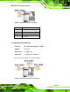
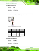
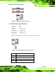
Figure 3-3: CPU Fan Connector Location
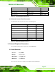
Pin Description
1 GND
2 +12 V
3 FANIN1
4 Fan Control1
Table 3-4: CPU Fan Connector Pinouts
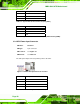
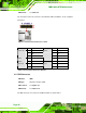
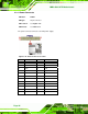
3.2.3 System Fan Connectors
CN Label: SYS_FAN1, SYS_FAN2, SYS_FAN3
CN Type:
3-pin wafer
CN Location:
See
Figure 3-4
CN Pinouts:
See
Table 3-5 and Table 3-6
The fan connector attaches to a system cooling fan.
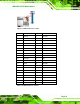
Figure 3-4: System Fan Connector Locations