
User guide

2011/8/172011/8/17
IMBA-G410 ATX Motherboard
Page 33
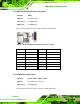
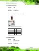
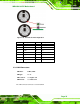
Figure 3-20: USB Connector Pinout Locations
Pin Description Pin Description
1 +5V 2 GND
3 USBP4/6# 4 USBP5/7
5 USBP4/6 6 USBP5/7#
7 GND 8 +5V
Table 3-20: USB Port Connector Pinouts
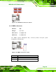
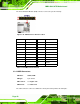
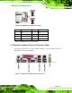
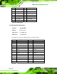
3.3 External Peripheral Interface Connector Panel
The figure below shows the external peripheral interface connector (EPIC) panel. The
EPIC panel consists of the following:
Figure 3-21: External Peripheral Interface Connector