User Manual
Manuals
Brands
IEI Integration Manuals
Hardware
IMBA-Q454 v1.01
11
12
13
14
15
16
17
18
19
20
IMBA-Q454-R10 User Manual
Page 20
1.2 Dat
a Flow
7
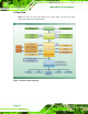
Figure 1-4
shows the data flow between the
system chipset, the CPU an
d other
components installed on th
e motherboard.
Figure 1-4: Data Flow Block Diagram
1
...
...
18
19
20
21
22
...
...
213