IMBA-Q670 ATX Motherboard IEI Technology Corp. MODEL: IMBA-Q670 ATX LGA1155 Motherboard for Intel® Core™ i7/i5/i3 Quad/Dual Core CPU, Intel® Q67 Chipset, DDR3, VGA/DVI/HDMI, Dual Intel® PCIe GbE, Intel® AMT 7.0 Support, Two USB 3.0 Ports, Five COM Ports, Two SATA 6Gb/s Ports and RoHS User Manual Page i Rev. 2.
IMBA-Q670 ATX Motherboard Revision Date Version Changes 1 October, 2012 2.10 Updated for R21 version: - Changed audio codec from Realtek ALC888 to ALC662 24 February, 2012 2.01 Modified Table 3-16: RS-422/485Connector Pinouts 9 September, 2011 2.00 Modified for R20 version 16 August, 2011 1.02 Modified Section 4.3.1: AT/ATX Power Select Jumper Added Section 4.6: Intel® AMT Setup Procedure Added Chapter 6: Software Drivers 30 June, 2011 1.01 Modified Section 4.2.
IMBA-Q670 ATX Motherboard Copyright COPYRIGHT NOTICE The information in this document is subject to change without prior notice in order to improve reliability, design and function and does not represent a commitment on the part of the manufacturer. In no event will the manufacturer be liable for direct, indirect, special, incidental, or consequential damages arising out of the use or inability to use the product or documentation, even if advised of the possibility of such damages.
IMBA-Q670 ATX Motherboard Table of Contents 1 INTRODUCTION.......................................................................................................... 1 1.1 INTRODUCTION........................................................................................................... 2 1.2 BENEFITS ................................................................................................................... 2 1.3 FEATURES ..........................................................................
IMBA-Q670 ATX Motherboard 3.2.11 Keyboard/Mouse Connector........................................................................... 28 3.2.12 Parallel Port Connector ................................................................................ 29 3.2.13 PCI Slots ........................................................................................................ 30 3.2.14 PCIe x1 Slot ................................................................................................... 31 3.2.
IMBA-Q670 ATX Motherboard 4.5 EXTERNAL PERIPHERAL INTERFACE CONNECTION ................................................... 62 4.5.1 Audio Connector .............................................................................................. 62 4.5.2 DVI Display Device Connection...................................................................... 63 4.5.3 HDMI Connection............................................................................................ 64 4.5.4 LAN Connection....................
IMBA-Q670 ATX Motherboard 5.4 CHIPSET ................................................................................................................. 101 5.4.1 Northbridge Configuration ............................................................................ 102 5.4.2 Southbridge Configuration ............................................................................ 104 5.4.3 Integrated Graphics ....................................................................................... 108 5.4.
IMBA-Q670 ATX Motherboard B.5.1 Factory Restore ............................................................................................. 175 B.5.2 Backup System ............................................................................................... 176 B.5.3 Restore Your Last Backup.............................................................................. 177 B.5.4 Manual........................................................................................................... 178 B.
IMBA-Q670 ATX Motherboard List of Figures Figure 1-1: IMBA-Q670 ...................................................................................................................2 Figure 1-2: Connectors ..................................................................................................................4 Figure 1-3: IMBA-Q670 Dimensions (mm)....................................................................................5 Figure 1-4: Data Flow Diagram.......................................
IMBA-Q670 ATX Motherboard Figure 3-27: External Peripheral Interface Connector ..............................................................42 Figure 3-28: Audio Connector .....................................................................................................43 Figure 3-29: Ethernet Connector.................................................................................................44 Figure 3-30: Serial Port Connector Pinouts..............................................................
IMBA-Q670 ATX Motherboard Figure 6-11: Graphics Driver Setup Operations ..................................................................... 124 Figure 6-12: Graphics Driver Installation Finish Screen ....................................................... 124 Figure 6-13: Intel® Network Connection Menu....................................................................... 125 Figure 6-14: LAN Driver Welcome Screen ..............................................................................
IMBA-Q670 ATX Motherboard Figure B-7: Manual Recovery Environment for Windows ..................................................... 158 Figure B-8: Building the Recovery Partition........................................................................... 159 Figure B-9: Press Any Key to Continue .................................................................................. 159 Figure B-10: Press F3 to Boot into Recovery Mode...............................................................
IMBA-Q670 ATX Motherboard Figure B-42: Disable Automatically Restart............................................................................
IMBA-Q670 ATX Motherboard List of Tables Table 1-1: IMBA-Q670 Specifications ...........................................................................................8 Table 2-1: Packing List.................................................................................................................12 Table 2-2: Optional Items.............................................................................................................13 Table 3-1: Peripheral Interface Connectors ......................
IMBA-Q670 ATX Motherboard Table 3-28: Serial Port Connector Pinouts ................................................................................46 Table 3-29: VGA Connector Pinouts...........................................................................................47 Table 3-30: DVI Connector Pinouts.............................................................................................47 Table 4-1: Jumpers ......................................................................................
IMBA-Q670 ATX Motherboard BIOS Menus BIOS Menu 1: Main .......................................................................................................................75 BIOS Menu 2: Advanced ..............................................................................................................76 BIOS Menu 3: ACPI Configuration ..............................................................................................77 BIOS Menu 4: TPM Configuration .......................................
IMBA-Q670 ATX Motherboard Chapter 1 1 Introduction Page 1
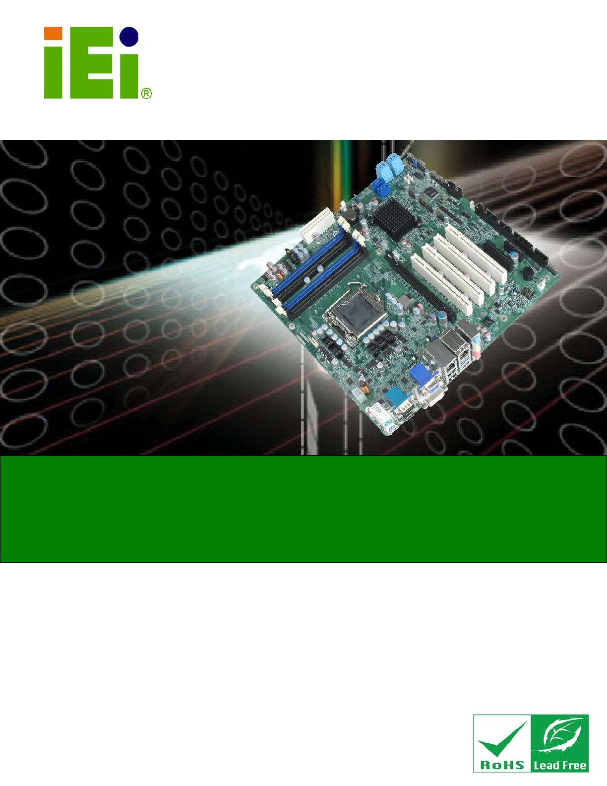
IMBA-Q670 ATX Motherboard 1.1 Introduction Figure 1-1: IMBA-Q670 The IMBA-Q670 is an ATX motherboard. It accepts a Socket LGA1155 Intel® Core™ i3/i5/i7 processor and supports four 240-pin 1333/1066 MHz dual-channel DDR3 DIMM modules up to 16.0 GB maximum. The IMBA-Q670 includes a VGA, HDMI, and DVI-D port. Expansion and I/O include four PCI card slots, one PCIe x16 card slot, one PCIe x4 card slot, one PCIe x1 slot, two USB 3.0 ports on the rear panel by NEC D720200F1, four USB 2.
IMBA-Q670 ATX Motherboard 1.
IMBA-Q670 ATX Motherboard 1.4 Connectors The connectors on the IMBA-Q670 are shown in the figure below.
IMBA-Q670 ATX Motherboard 1.5 Dimensions The main dimensions of the IMBA-Q670 are shown in the diagram below.
IMBA-Q670 ATX Motherboard 1.6 Data Flow Figure 1-4 shows the data flow between the system chipset, the CPU and other 7 components installed on the motherboard.
IMBA-Q670 ATX Motherboard 1.7 Technical Specifications IMBA-Q670 technical specifications are listed below. Specification/Model IMBA-Q670 Form Factor ATX CPU Supported LGA1155 Intel® Core™ i7/i5/i3 quad/dual core CPU Chipset Intel® Q67 Integrated Graphics Supports DirectX 10.1/OpenGL 3.0 Full MPEG2, VC1, AVC Decode Memory Four 240-pin 1333/1066 MHz dual-channel DDR3 SDRAM unbuffered DIMMs support (system max. 16.0 GB) Graphic Engine Support for DX10.1 and OpenGL3.
IMBA-Q670 ATX Motherboard Specification/Model IMBA-Q670 Display port One VGA Integrated in the Intel® Q67 One HDMI Integrated in the Intel® Q67 One DVI-D Integrated in the Intel® Q67 Ethernet Two RJ-45 GbE ports Keyboard/Mouse Dual PS/2 port One internal keyboard and mouse connector via 6-pin wafer TPM One via 20-pin header Serial Ports One external RS-232 serial port Four RS-232 via internal box headers One RS-422/485 via internal 4-pin wafer Parallel Port One parallel port via internal 26-pin b
IMBA-Q670 ATX Motherboard Chapter 2 2 Packing List Page 9
IMBA-Q670 ATX Motherboard 2.1 Anti-static Precautions WARNING! Static electricity can destroy certain electronics. Make sure to follow the ESD precautions to prevent damage to the product, and injury to the user. Make sure to adhere to the following guidelines: Wear an anti-static wristband: Wearing an anti-static wristband can prevent electrostatic discharge. Self-grounding: Touch a grounded conductor every few minutes to discharge any excess static buildup.
IMBA-Q670 ATX Motherboard 2.3 Packing List NOTE: If any of the components listed in the checklist below are missing, do not proceed with the installation. Contact the IEI reseller or vendor the IMBA-Q670 was purchased from or contact an IEI sales representative directly by sending an email to sales@iei.com.tw.
IMBA-Q670 ATX Motherboard Quantity Item and Part Number 1 Quick Installation Guide Image Table 2-1: Packing List 2.
IMBA-Q670 ATX Motherboard Item and Part Number Image Dual RS-232 cable (P/N: 19800-000051-RS) 20-pin INFINEON TPM module, S/W management tool (P/N: TPM-IN01-R11) Table 2-2: Optional Items Page 13
IMBA-Q670 ATX Motherboard Chapter 3 3 Connectors Page 14
IMBA-Q670 ATX Motherboard 3.1 Peripheral Interface Connectors This chapter details all the jumpers and connectors. 3.1.1 IMBA-Q670 Layout The figures below show all the connectors and jumpers.
IMBA-Q670 ATX Motherboard 3.1.2 Peripheral Interface Connectors The table below lists all the connectors on the board.
IMBA-Q670 ATX Motherboard Connector Type Label Serial port, RS-422/485 4-pin wafer COM4 Serial port, RS-232 10-pin box header COM1, COM2, COM3, COM5 SMBus connector 4-pin wafer SMBUS_1 SPDIF connector 5-pin header SPDIF1 SPI ROM connector 8-pin header JSPI1 TPM connector 20-pin header TPM1 USB connectors 8-pin header USB1, USB2, USB3, USB4 Table 3-1: Peripheral Interface Connectors 3.1.
IMBA-Q670 ATX Motherboard 3.2 Internal Peripheral Connectors The section describes all of the connectors on the IMBA-Q670. 3.2.1 ATX Power Connector CN Label: ATX1 CN Type: 24-pin ATX CN Location: See Figure 3-2 CN Pinouts: See Table 3-3 The ATX power connector connects to an ATX power supply. Figure 3-2: ATX Power Connector Pinout Location Pin Description Pin Description 1 +3.3V 13 +3.3V 2 +3.
IMBA-Q670 ATX Motherboard Pin Description Pin Description 8 NC 20 NC 9 +5V 21 +5V 10 +12V 22 +5V 11 +12V 23 +5V 12 +3.3V 24 GND Table 3-3: ATX Power Connector Pinouts 3.2.2 Battery Connectors CAUTION: Risk of explosion if battery is replaced by and incorrect type. Only certified engineers should replace the on-board battery. Dispose of used batteries according to instructions and local regulations.
IMBA-Q670 ATX Motherboard Figure 3-3: Battery Connector Locations Pin Description 1 GND 2 Battery+ Table 3-4: Battery Connector (BT2) Pinouts 3.2.3 CPU Power Connector CN Label: CPU12V1 CN Type: 4-pin Molex CN Location: See Figure 3-4 CN Pinouts: See Table 3-5 The CPU power input connector provides power to the CPU.
IMBA-Q670 ATX Motherboard Figure 3-4: CPU Power Connector Location PIN NO. DESCRIPTION 1 GND 2 GND 3 +12V 4 +12V Table 3-5: CPU Power Connector Pinouts 3.2.4 DDR3 DIMM Slots CN Label: CHA_DIMM1, CHA_DIMM2, CHB_DIMM1, CHB_DIMM2 CN Type: DDR3 DIMM slot CN Location: See Figure 3-5 8 The DIMM slots are for DDR3 DIMM memory modules.
IMBA-Q670 ATX Motherboard Figure 3-5: DDR3 DIMM Slot Locations 3.2.5 Digital I/O Connector CN Label: DIO1 CN Type: 10-pin header CN Location: See Figure 3-6 CN Pinouts: See Table 3-6 The digital I/O connector provides programmable input and output for external devices. The digital I/O provides 4-bit output and 4-bit input.
IMBA-Q670 ATX Motherboard Figure 3-6: Digital I/O Connector Location PIN NO. DESCRIPTION PIN NO. DESCRIPTION 1 GND 2 VCC 3 Output 3 4 Output 2 5 Output 1 6 Output 0 7 Input 3 8 Input 2 9 Input 1 10 Input 0 Table 3-6: Digital I/O Connector Pinouts 3.2.6 Fan Connector (CPU) CN Label: CPU_FAN1 CN Type: 4-pin wafer CN Location: See Figure 3-7 CN Pinouts: See Table 3-7 The fan connector attaches to a CPU cooling fan.
IMBA-Q670 ATX Motherboard Figure 3-7: CPU Fan Connector Location PIN NO. DESCRIPTION 1 GND 2 +12 V 3 FANIO1 4 PWM Table 3-7: CPU Fan Connector Pinouts 3.2.7 Fan Connector (System) CN Label: SYS_FAN1, SYS_FAN2 CN Type: 3-pin wafer CN Location: See Figure 3-8 CN Pinouts: See Table 3-8 The fan connector attaches to a cooling fan.
IMBA-Q670 ATX Motherboard Figure 3-8: System Fan Connector Locations PIN NO. DESCRIPTION 1 FANIO 2 +12 V (PWM) 3 GND Table 3-8: System Fan Connector Pinouts 3.2.8 Front Panel Audio Connector CN Label: FP_AUDIO1 CN Type: 10-pin header CN Location: See Figure 3-9 CN Pinouts: See Table 3-9 This connector connects to speakers, a microphone and an audio input.
IMBA-Q670 ATX Motherboard Figure 3-9: Front Panel Audio Connector Location Pin Description Pin Description 1 LMIC2_L 2 AUD GND 3 LMIC2_R 4 PRESENCE# 5 LLINE2-R 6 MIC2-JD 7 F_SENSE 8 NC 9 LLINE2-L 10 LINE2-JD Table 3-9: Front Panel Audio Connector Pinouts 3.2.
IMBA-Q670 ATX Motherboard Figure 3-10: Front Panel Connector Location FUNCTION PIN DESCRIPTION FUNCTION PIN DESCRIPTION Power LED 1 ACPILED Speaker 2 Beep Power 3 NC 4 NC 5 GND 6 NC 7 PWRBT_SW#_C 8 PC Beep 9 GND 10 NC 11 HDDLED 12 EXTRST- 13 HDDLED- 14 GND Power Button HDD LED Reset Table 3-10: Front Panel Connector Pinouts 3.2.
IMBA-Q670 ATX Motherboard Figure 3-11: I2C Connector Location Pin Description 1 +5V_DUAL 2 PCH_GP38_PU 3 PCH_GP39_PU 4 GND Table 3-11: I2C Connector Pinouts 3.2.11 Keyboard/Mouse Connector CN Label: KB_MS1 CN Type: 6-pin wafer CN Location: See Figure 3-12 CN Pinouts: See Table 3-12 The keyboard/mouse connector connects to a PS/2 Y-cable that can be connected to a PS/2 keyboard and mouse.
IMBA-Q670 ATX Motherboard Figure 3-12: Keyboard/Mouse Connector Location Pin Description 1 +5 V KB DATA 2 MS DATA 3 MS CLK 4 KB DATA 5 KB CLK 6 GROUND Table 3-12: Keyboard/Mouse Connector Pinouts 3.2.12 Parallel Port Connector CN Label: LPT1 CN Type: 26-pin box header CN Location: See Figure 3-13 CN Pinouts: See Table 3-13 The parallel port connector connects to a parallel port connector interface or some other parallel port device such as a printer.
IMBA-Q670 ATX Motherboard Figure 3-13: Parallel Port Connector Location Pin Description Pin Description 1 RSTROBE# 2 RPD0 3 RPD1 4 RPD2 5 RPD3 6 RPD4 7 RPD5 8 RPD6 9 RPD7 10 SIO_ACK# 11 SIO_BUSY 12 SIO_PE 13 SIO_SLCT 14 SIO_AFD# 15 SIO_ERR# 16 SIO_INIT# 17 SIO_SLIN# 18 GND 19 GND 20 GND 21 GND 22 GND 23 GND 24 GND 25 GND 26 NC Table 3-13: Parallel Port Connector Pinouts 3.2.
IMBA-Q670 ATX Motherboard The PCI slot enables a PCI expansion module to be connected to the board. Figure 3-14: PCI Slot Locations 3.2.14 PCIe x1 Slot CN Label: PCIEX4_1 CN Type: PCIe x1 slot CN Location: See Figure 3-18 The PCIe x1 slot provides PCIe x1 signal for PCIe expansion cards.
IMBA-Q670 ATX Motherboard 3.2.15 PCIe x4 Slot CN Label: PCIEX4_2 CN Type: PCIe x4 slot CN Location: See Figure 3-18 The PCIe x4 slot is for PCIe x4 expansion cards. Figure 3-16: PCIe x4 Slot Location 3.2.16 PCIe x16 Slot CN Label: PCIEX16_1 CN Type: PCIe x16 slot CN Location: See Figure 3-17 The PCIe x16 expansion cards slot is for PCIe x16 expansion cards.
IMBA-Q670 ATX Motherboard Figure 3-17: PCIe x16 Slot Location 3.2.17 SATA 3Gb/s Drive Connector CN Label: SATA34, SATA56 CN Type: 14-pin SATA connector CN Location: See Figure 3-18 CN Pinouts: See Table 3-14 The SATA drive connectors can be connected to SATA drives and support up to 3Gb/s data transfer rate.
IMBA-Q670 ATX Motherboard Figure 3-18: SATA 3Gb/s Drive Connector Location Pin Description Pin Description 1 GND 8 GND 2 SATATXP_A 9 SATATXP_B 3 SATATXN_A 10 SATATXN_B 4 GND 11 GND 5 SATARXN_A 12 SATARXN_B 6 SATARXP_A 13 SATARXP_B 7 GND 14 GND Table 3-14: SATA 3Gb/s Drive Connector Pinouts 3.2.
IMBA-Q670 ATX Motherboard Figure 3-19: SATA 6Gb/s Drive Connector Location Pin Description 1 GND 2 SATATXP 3 SATATXN 4 GND 5 SATARXN 6 SATARXP 7 GND Table 3-15: SATA 6Gb/s Drive Connector Pinouts 3.2.
IMBA-Q670 ATX Motherboard NOTE: These pins are shared with those on the main serial port. Use either the pins on the main connector, or on this connector, but not both. This connector provides RS-422 or RS-485 communications. Figure 3-20: RS-422/485 Connector Location PIN NO. DESCRIPTION PIN NO. DESCRIPTION 1 RXD485# 3 TXD485+ 2 RXD485+ 4 TXD485# Table 3-16: RS-422/485Connector Pinouts 3.2.
IMBA-Q670 ATX Motherboard Figure 3-21: Serial Port Connector Location PIN NO. DESCRIPTION PIN NO. DESCRIPTION 1 -NDCD1 6 -NCTS1 2 -NDSR1 7 -NDTR1 3 NSIN1 8 -XRI1 4 -NRTS1 9 GND 5 NSOUT1 10 GND Table 3-17: Serial Port Connector Pinouts 3.2.21 SMBus Connector CN Label: SMBUS_1 CN Type: 4-pin wafer CN Location: See Figure 3-22 CN Pinouts: See Table 3-18 The SMBus (System Management Bus) connector provides low-speed system management communications.
IMBA-Q670 ATX Motherboard Figure 3-22: SMBus Connector Location Pin Description 1 +5V_DUAL 2 SMBCLK 3 SMBDATA 4 GND Table 3-18: SMBus Connector Pinouts 3.2.22 SPDIF Connector CN Label: SPDIF1 CN Type: 5-pin header CN Location: See Figure 3-23 CN Pinouts: See Table 3-19 Use the SPDIF connector to connect digital audio devices to the system.
IMBA-Q670 ATX Motherboard Figure 3-23: SPDIF Connector Location PIN DESCRIPTION 1 +5V 2 NC 3 SPDIFOUT 4 GND 5 SPDIFIN Table 3-19: SPDIF Connector Pinouts 3.2.23 SPI ROM Connector CN Label: JSPI1 CN Type: 8-pin header CN Location: See Figure 3-8 CN Pinouts: See Table 3-8 The SPI connector is used to flash the BIOS.
IMBA-Q670 ATX Motherboard Figure 3-24: SPI Connector Location PIN NO. DESCRIPTION PIN NO. DESCRIPTION 1 +3.3V 2 GND 3 SPI_CS0 4 SPI_CLK 5 SPI_SO0 6 SPI_SI 7 NC 8 NC Table 3-20: SPI Connector Pinouts 3.2.24 TPM Connector CN Label: TPM1 CN Type: 20-pin header CN Location: See Figure 3-8 CN Pinouts: See Table 3-8 The TPM connector connects to a TPM module.
IMBA-Q670 ATX Motherboard Figure 3-25: TPM Connector Location PIN NO. DESCRIPTION PIN NO. DESCRIPTION 1 LCLK 2 GND2 3 LERAME# 4 KEY 5 LRESRT# 6 +5V 7 LAD3 8 LAD2 9 +3V 10 LAD1 11 LAD0 12 GND3 13 SCL 14 SDA 15 SB3V 16 SERIRQ 17 GND1 18 GLKRUN# 19 LPCPD# 20 LDRQ# Table 3-21: TPM Connector Pinouts 3.2.
IMBA-Q670 ATX Motherboard Figure 3-26: USB Connector Pinout Locations PIN NO. DESCRIPTION PIN NO. DESCRIPTION 1 +5V 2 GND 3 DATA- 4 DATA+ 5 DATA+ 6 DATA- 7 GND 8 +5V Table 3-22: USB Port Connector Pinouts 3.3 External Peripheral Interface Connector Panel The figure below shows the external peripheral interface connector (EPIC) panel.
IMBA-Q670 ATX Motherboard 3.3.1 Audio Connector CN Label: AUDIO_CV1 CN Type: Audio jack CN Location: See Figure 3-27 The audio jacks connect to external audio devices. Line In port (Light Blue): Connects a CD-ROM, DVD player, or other audio devices. Line Out port (Lime): Connects to a headphone or a speaker. With multi-channel configurations, this port can also connect to front speakers. Microphone (Pink): Connects a microphone. Figure 3-28: Audio Connector 3.3.
IMBA-Q670 ATX Motherboard PIN DESCRIPTION PIN DESCRIPTION 3 MDIA2- 4 MDIA1- 5 MDIA1+ 6 MDIA2+ 7 MDIA0- 8 MDIA0+ Table 3-23: LAN Pinouts Figure 3-29: Ethernet Connector LED Description LED Description A on: linked B off: 10 Mb/s blinking: data is being sent/received green: 100 Mb/s orange: 1000 Mb/s Table 3-24: Connector LEDs The USB connector can be connected to a USB device. The USB 2.0 ports are labeled as USB01 and the USB 3.0 ports are labels as USB23.
IMBA-Q670 ATX Motherboard The HDMI port connects to an HDMI device. PIN NO. DESCRIPTION PIN NO. DESCRIPTION 1 HDMI_DATA2 13 N/C 2 GND 14 N/C 3 HDMI_DATA2# 15 HDMI_SCL 4 HDMI_DATA1 16 HDMI_SDA 5 GND 17 GND 6 HDMI_DATA1# 18 +5V 7 HDMI_DATA0 19 HDMI_HPD 8 GND 20 HDMI_GND 9 HDMI_DATA0# 21 HDMI_GND 10 HDMI_CLK 22 HDMI_GND 11 GND 23 HDMI_GND 12 HDMI_CLK# Table 3-26: HDMI Connector Pinouts 3.3.
IMBA-Q670 ATX Motherboard 3.3.5 Serial Port Connectors (COM6) CN Label: COM6 CN Type: DB-9 connector CN Location: See Figure 3-27 CN Pinouts: See Table 3-28 and Figure 3-30 The serial port connects to a RS-232 serial communications device. PIN NO. DESCRIPTION PIN NO. DESCRIPTION 1 NDCD 6 NDSR 2 NRXD 7 NRTS 3 NTXD 8 NCTS 4 NDTR 9 NRI 5 GND Table 3-28: Serial Port Connector Pinouts Figure 3-30: Serial Port Connector Pinouts 3.3.
IMBA-Q670 ATX Motherboard PIN DESCRIPTION PIN DESCRIPTION 1 CRT_RED 2 CRT_GREEN 3 CRT_BLUE 4 NC 5 GND 6 GND 7 GND 8 GND 9 +5V CRT 10 CRT_PLUG# 11 NC 12 CRT_DDC_DATA 13 CRT_HSYNC 14 CRT_VSYNC 15 CRT_DDC_CLK Table 3-29: VGA Connector Pinouts Figure 3-31: VGA Connector The DVI connector connects to a monitor that supports DVI video input.
IMBA-Q670 ATX Motherboard Chapter 4 4 Installation Page 48
IMBA-Q670 ATX Motherboard 4.1 Anti-static Precautions WARNING: Failure to take ESD precautions during the installation of the IMBA-Q670 may result in permanent damage to the IMBA-Q670 and severe injury to the user. Electrostatic discharge (ESD) can cause serious damage to electronic components, including the IMBA-Q670. Dry climates are especially susceptible to ESD.
IMBA-Q670 ATX Motherboard WARNING: The installation instructions described in this manual should be carefully followed in order to prevent damage to the components and injury to the user. Before and during the installation please DO the following: Read the user manual: o The user manual provides a complete description of the IMBA-Q670 installation instructions and configuration options. Wear an electrostatic discharge cuff (ESD): o Electronic components are easily damaged by ESD.
IMBA-Q670 ATX Motherboard 4.2.1 Socket LGA1155 CPU Installation WARNING: CPUs are expensive and sensitive components. When installing the CPU please be careful not to damage it in anyway. Make sure the CPU is installed properly and ensure the correct cooling kit is properly installed. DO NOT touch the pins at the bottom of the CPU. When handling the CPU, only hold it on the sides. To install the CPU, follow the steps below.
IMBA-Q670 ATX Motherboard Figure 4-2: Remove Protective Cover Step 3: Inspect the CPU socket. Make sure there are no bent pins and make sure the socket contacts are free of foreign material. If any debris is found, remove it with compressed air. Step 4: Orientate the CPU properly. The contact array should be facing the CPU socket. Step 5: Correctly position the CPU. Match the Pin 1 mark with the cut edge on the CPU socket. Step 6: Align the CPU pins. Locate pin 1 and the two orientation notches on the CPU.
IMBA-Q670 ATX Motherboard Figure 4-3: Insert the Socket LGA1155 CPU Step 8: Close the CPU socket. Close the load plate and pull the load lever back a little to have the load plate be able to secure to the knob. Engage the load lever by pushing it back to its original position (Figure 4-4). There will be some resistance, but will not require extreme pressure. Figure 4-4: Close the Socket LGA1155 Step 9: Connect the 12 V power to the board. Connect the 12 V power from the power supply to the board.
IMBA-Q670 ATX Motherboard 4.2.2 Socket LGA1155 Cooling Kit Installation WARNING: DO NOT attempt to install a push-pin cooling fan. The pre-installed support bracket prevents the board from bending and is ONLY compatible with captive screw type cooling fans. Figure 4-5: Cooling Kits (CF-1156A-RS and CF-1156B-RS) The cooling kit can be bought from IEI. The cooling kit has a heatsink and fan.
IMBA-Q670 ATX Motherboard Figure 4-6: Cooling Kit Support Bracket Step 2: Place the cooling kit onto the socket LGA1155 CPU. Make sure the CPU cable can be properly routed when the cooling kit is installed. Step 3: Mount the cooling kit. Gently place the cooling kit on top of the CPU. Make sure the four threaded screws on the corners of the cooling kit properly pass through the holes of the cooling kit bracket. Step 4: Secure the cooling kit by fastening the four retention screws of the cooling kit.
IMBA-Q670 ATX Motherboard 4.2.3 DIMM Installation To install a DIMM, please follow the steps below and refer to Figure 4-7. Figure 4-7: DIMM Installation Step 1: Open the DIMM socket handles. Open the two handles outwards as far as they can. See Figure 4-7. Step 2: Align the DIMM with the socket. Align the DIMM so the notch on the memory lines up with the notch on the memory socket. See Figure 4-7. Step 3: Insert the DIMM. Once aligned, press down until the DIMM is properly seated.
IMBA-Q670 ATX Motherboard 4.3 Jumper Settings NOTE: A jumper is a metal bridge used to close an electrical circuit. It consists of two or three metal pins and a small metal clip (often protected by a plastic cover) that slides over the pins to connect them. To CLOSE/SHORT a jumper means connecting the pins of the jumper with the plastic clip and to OPEN a jumper means removing the plastic clip from a jumper. The hardware jumpers must be set before installation. Jumpers are shown in Table 4-1.
IMBA-Q670 ATX Motherboard Setting Description Closed ATX power (Default) Open AT power Table 4-2: AT/ATX Power Mode Jumper Settings Figure 4-8: AT/ATX Power Mode Jumper Location 4.3.2 Clear CMOS Jumper Jumper Label: J_CMOS1 Jumper Type: 3-pin header Jumper Settings: See Table 4-3 Jumper Location: See Figure 4-9 To reset the BIOS, move the jumper to the "Clear BIOS" position for 3 seconds or more, and then move back to the default position.
IMBA-Q670 ATX Motherboard Figure 4-9: Clear BIOS Jumper Location 4.3.3 Wake-on LAN Jumper CN Label: WOL_SEL1 CN Type: 3-pin header CN Location: See Figure 4-10 CN Pinouts: See Table 4-4 The Wake-on LAN connector allows the user to enable or disable the Wake-on LAN (WOL) function. PIN NO.
IMBA-Q670 ATX Motherboard Figure 4-10: Wake-on LAN Connector Pinout Locations 4.4 Internal Peripheral Device Connections This section outlines the installation of peripheral devices to the onboard connectors. 4.4.1 SATA Drive Connection The IMBA-Q670 is shipped with four SATA drive cables. To connect the SATA drives to the connectors, please follow the steps below. Step 1: Locate the connectors. The locations of the SATA drive connectors are shown in Chapter 3. Step 2: Insert the cable connector.
IMBA-Q670 ATX Motherboard Figure 4-11: SATA Drive Cable Connection Step 3: Connect the cable to the SATA disk. Connect the connector on the other end of the cable to the connector at the back of the SATA drive. See Figure 4-12. Step 4: Connect the SATA power cable (optional). Connect the SATA power connector to the back of the SATA drive. See Figure 4-12.
IMBA-Q670 ATX Motherboard Figure 4-12: SATA Power Drive Connection The SATA power cable can be bought from IEI. See Optional Items in Section 2.4. 4.5 External Peripheral Interface Connection This section describes connecting devices to the external connectors on the IMBA-Q670. 4.5.1 Audio Connector The audio jacks on the external audio connector enable the IMBA-Q670 to be connected to a stereo sound setup. Each jack supports both input and output.
IMBA-Q670 ATX Motherboard Step 2: Plug the audio plugs into the audio jacks. Plug the audio plugs into the audio jacks. If the plugs on your speakers are different, an adapter will need to be used to plug them into the audio jacks. Figure 4-13: Audio Connector Step 3: Check audio clarity. Check that the sound is coming through the right speakers by adjusting the balance front to rear and left to right. 4.5.
IMBA-Q670 ATX Motherboard Step 3: Insert the DVI-I connector. Once the connectors are properly aligned with the male connector, insert the male connector from the digital display device into the female connector on the IMBA-Q670. See Figure 4-14. Figure 4-14: DVI Connector Step 4: Secure the connector. Secure the DVI-I connector from the digital display device to the external interface by tightening the two retention screws on either side of the connector. Step 0: 4.5.
IMBA-Q670 ATX Motherboard Step 3: Insert the HDMI connector. Gently insert the HDMI connector. The connector should engage with a gentle push. If the connector does not insert easily, check again that the connector is aligned correctly, and that the connector is being inserted with the right way up. Step 0: Figure 4-15: HDMI Connection 4.5.4 LAN Connection There are two external RJ-45 LAN connectors. The RJ-45 connectors enable connection to an external network.
IMBA-Q670 ATX Motherboard Figure 4-16: LAN Connection Step 3: Insert the LAN cable RJ-45 connector. Once aligned, gently insert the LAN cable RJ-45 connector into the on-board RJ-45 connector. Step 0: 4.5.5 PS/2 Keyboard and Mouse Connection The IMBA-Q670 has a dual PS/2 connector on the external peripheral interface panel. The dual PS/2 connector is used to connect to a keyboard and mouse to the system. Follow the steps below to connect a keyboard and mouse to the IMBA-Q670.
IMBA-Q670 ATX Motherboard Figure 4-17: PS/2 Keyboard/Mouse Connector 4.5.6 Serial Device Connection The IMBA-Q670 has a single female DB-9 connector on the external peripheral interface panel for a serial device. Follow the steps below to connect a serial device to the IMBA-Q670. Step 1: Locate the DB-9 connector. The location of the DB-9 connector is shown in Chapter 3. Step 2: Insert the serial connector.
IMBA-Q670 ATX Motherboard Figure 4-18: Serial Device Connector Step 3: Secure the connector. Secure the serial device connector to the external interface by tightening the two retention screws on either side of the connector. Step 0: 4.5.7 USB Connection (Dual Connector) The external USB Series "A" receptacle connectors provide easier and quicker access to external USB devices. Follow the steps below to connect USB devices to the IMBA-Q670. Step 1: Locate the USB Series "A" receptacle connectors.
IMBA-Q670 ATX Motherboard Figure 4-19: USB Connector 4.5.8 VGA Monitor Connection The IMBA-Q670 has a single female DB-15 connector on the external peripheral interface panel. The DB-15 connector is connected to a CRT or VGA monitor. To connect a monitor to the IMBA-Q670, please follow the instructions below. Step 1: Locate the female DB-15 connector. The location of the female DB-15 connector is shown in Chapter 3. Step 2: Align the VGA connector.
IMBA-Q670 ATX Motherboard Figure 4-20: VGA Connector Step 4: Secure the connector. Secure the DB-15 VGA connector from the VGA monitor to the external interface by tightening the two retention screws on either side of the connector. Step 0: 4.6 Intel® AMT Setup Procedure The IMBA-Q670 is featured with the Intel® Active Management Technology (AMT). To enable the Intel® AMT function, follow the steps below. Step 1: Make sure the CHA_DIMM1 socket is installed with one DDR3 DIMM.
IMBA-Q670 ATX Motherboard process. Enter the Intel® current ME password as it requires (the Intel® default password is admin). NOTE: To change the password, enter a new password following the strong password rule (containing at least one upper case letter, one lower case letter, one digit and one special character, and be at least eight characters).
IMBA-Q670 ATX Motherboard Chapter 5 5 BIOS Page 72
IMBA-Q670 ATX Motherboard 5.1 Introduction The BIOS is programmed onto the BIOS chip. The BIOS setup program allows changes to certain system settings. This chapter outlines the options that can be changed. 5.1.1 Starting Setup The UEFI BIOS is activated when the computer is turned on. The setup program can be activated in one of two ways. 1. Press the DEL or F2 key as soon as the system is turned on or 2. Press the DEL or F2 key when the “Press DEL or F2 to enter SETUP” message appears on the screen. 0.
IMBA-Q670 ATX Motherboard Key Function Esc key Main Menu – Quit and not save changes into CMOS Status Page Setup Menu and Option Page Setup Menu -Exit current page and return to Main Menu F1 General help, only for Status Page Setup Menu and Option Page Setup Menu F2 Previous values F3 Load optimized defaults F4 Save changes and Exit BIOS Table 5-1: BIOS Navigation Keys 5.1.
IMBA-Q670 ATX Motherboard 5.2 Main The Main BIOS menu (BIOS Menu 1) appears when the BIOS Setup program is entered. The Main menu gives an overview of the basic system information. Aptio Setup Utility – Copyright (C) 2011 American Megatrends, Inc. Main Advanced Chipset Boot Security Save & Exit BIOS Information BIOS Vendor Core Version Compliency Project Version Build Date American Megatrends 4.6.4.0 0.03 UEFI 2.0 B216AR10.ROM 07/22/2011 17:06:33 Set the Date. Use Tab to switch between Data elements.
IMBA-Q670 ATX Motherboard Î System Date [xx/xx/xx] Use the System Date option to set the system date. Manually enter the day, month and year. Î System Time [xx:xx:xx] Use the System Time option to set the system time. Manually enter the hours, minutes and seconds. 5.3 Advanced Use the Advanced menu (BIOS Menu 2) to configure the CPU and peripheral devices through the following sub-menus: WARNING! Setting the wrong values in the sections below may cause the system to malfunction.
IMBA-Q670 ATX Motherboard 5.3.1 ACPI Settings The ACPI Settings menu (BIOS Menu 3) configures the Advanced Configuration and Power Interface (ACPI) options. Aptio Setup Utility – Copyright (C) 2010 American Megatrends, Inc. Advanced ACPI Settings ACPI Sleep State [S1 (CPU Stop Clock)] Select the highest ACPI sleep state the system will enter when the SUSPEND button is pressed. ---------------------ÅÆ: Select Screen ↑ ↓: Select Item Enter Select + - Change Opt.
IMBA-Q670 ATX Motherboard 5.3.2 Trusted Computing Use the Trusted Computing menu (BIOS Menu 4) to configure settings related to the Trusted Computing Group (TCG) Trusted Platform Module (TPM). Aptio Setup Utility – Copyright (C) 2011 American Megatrends, Inc. Advanced TPM Configuration TPM SUPPORT [Disable] Current TPM Status Information NO TPM Hardware Enables or Disables TPM support. O.S. will not show TPM. Reset of platform is required.
IMBA-Q670 ATX Motherboard Aptio Setup Utility – Copyright (C) 2011 American Megatrends, Inc. Advanced CPU Configuration Socket specific CPU Information > CPU Information Intel Virtualization Technology [Disabled] ---------------------- ÅÆ: Select Screen ↑ ↓: Select Item Enter Select + - Change Opt. F1 General Help F2 Previous Values F3 Optimized Defaults F4 Save & Exit ESC Exit Version 2.11.1210. Copyright (C) 2011 American Megatrends, Inc.
IMBA-Q670 ATX Motherboard Aptio Setup Utility – Copyright (C) 2011 American Megatrends, Inc. Advanced CPU Configuration Intel(R) Core(TM) i5-2400 CPU 0 @ 3.10GHz CPU Signature 206a7 Microcode Patch 14 Max CPU Speed 3100 MHz Min CPU Speed 1600 MHz Processor Cores 4 Intel HT Technology Not Supported Intel VT-x Technology Supported Intel SMX Technology supported L1 L1 L2 L3 ---------------------ÅÆ: Select Screen ↑ ↓: Select Item Enter Select + - Change Opt.
IMBA-Q670 ATX Motherboard 5.3.4 SATA Configuration Use the SATA Configuration menu (BIOS Menu 7) to change and/or set the configuration of the SATA devices installed in the system. Aptio Setup Utility – Copyright (C) 2011 American Megatrends, Inc. Advanced SATA Configuration (1) IDE Mode. (2) AHCI Mode. (3) RAID Mode.
IMBA-Q670 ATX Motherboard Î Î Disable Disables SATA devices. Î IDE Mode Configures SATA devices as normal IDE device. Î AHCI Mode Î RAID Mode DEFAULT Configures SATA devices as AHCI device. Configures SATA devices as RAID device. Staggered Spin-up [Disabled] Staggered Spin-up allows the system to power up one drive at a time to prevent excess power consumption. Use the Staggered Spin-up option to enable or disable the staggered spin-up function.
IMBA-Q670 ATX Motherboard Aptio Setup Utility – Copyright (C) 2011 American Megatrends, Inc. Advanced Intel Trusted Execution Technology Configuration Intel TXT support only can be enabled/disabled if SMX is enabled. VT and VT-d support must also be enabled prior to TXT. Secure Mode Extensons (SMX) Enabled Intel TXT(LT) Support [Disabled] --------------------ÅÆ: Select Screen ↑ ↓: Select Item Enter Select + - Change Opt.
IMBA-Q670 ATX Motherboard Î USB Support [Enabled] Use the USB Support option to enable or disable USB support on the system. Î Î Disabled Î Enabled USB support disabled DEFAULT USB support enabled Legacy USB Support [Enabled] Use the Legacy USB Support BIOS option to enable USB mouse and USB keyboard support. Normally if this option is not enabled, any attached USB mouse or USB keyboard does not become available until a USB compatible operating system is fully booted with all USB drivers loaded.
IMBA-Q670 ATX Motherboard 5.3.7 Super IO Configuration Use the Super IO Configuration menu (BIOS Menu 10) to set or change the configurations for the FDD controllers, parallel ports and serial ports. Aptio Setup Utility – Copyright (C) 2011 American Megatrends, Inc.
IMBA-Q670 ATX Motherboard 5.3.7.1 Serial Port n Configuration Use the Serial Port n Configuration menu (BIOS Menu 11) to configure the serial port n. Aptio Setup Utility – Copyright (C) 2011 American Megatrends, Inc. Advanced Serial Port n Configuration Serial Port Device Settings Enable or Disable Serial Port (COM) [Enabled] IO=3F8h; IRQ=4 --------------------ÅÆ: Select Screen ↑ ↓: Select Item Enter Select = - Change Opt.
IMBA-Q670 ATX Motherboard Î Î Î Î IO=3F8h; Serial Port I/O port address is 3F8h and the interrupt IRQ=3, 4 address is IRQ3, 4 IO=2F8h; Serial Port I/O port address is 2F8h and the interrupt IRQ=3, 4 address is IRQ3, 4 IO=2C0h; Serial Port I/O port address is 2C0h and the interrupt IRQ=3, 4 address is IRQ3, 4 IO=2C8h; Serial Port I/O port address is 2C8h and the interrupt IRQ=3, 4 address is IRQ3, 4 5.3.7.1.
IMBA-Q670 ATX Motherboard Î IO=2C8h; Serial Port I/O port address is 2C8h and the interrupt IRQ=3, 4 address is IRQ3, 4 5.3.7.1.3 Serial Port 3 Configuration Î Serial Port [Enabled] Use the Serial Port option to enable or disable the serial port. Î Î Disabled Î Enabled Disable the serial port DEFAULT Enable the serial port Change Settings [Auto] Use the Change Settings option to change the serial port IO port address and interrupt address.
IMBA-Q670 ATX Motherboard 5.3.7.1.4 Serial Port 4 Configuration Î Serial Port [Enabled] Use the Serial Port option to enable or disable the serial port. Î Î Disabled Î Enabled Disable the serial port DEFAULT Enable the serial port Change Settings [Auto] Use the Change Settings option to change the serial port IO port address and interrupt address. Î Auto DEFAULT The serial port IO port address and interrupt address are automatically detected.
IMBA-Q670 ATX Motherboard 5.3.7.1.5 Serial Port 5 Configuration Î Serial Port [Enabled] Use the Serial Port option to enable or disable the serial port. Î Î Disabled Î Enabled Disable the serial port DEFAULT Enable the serial port Change Settings [Auto] Use the Change Settings option to change the serial port IO port address and interrupt address. Î Auto DEFAULT The serial port IO port address and interrupt address are automatically detected.
IMBA-Q670 ATX Motherboard Î Î Disabled Î Enabled Disable the serial port DEFAULT Enable the serial port Change Settings [Auto] Use the Change Settings option to change the serial port IO port address and interrupt address. Î Auto DEFAULT The serial port IO port address and interrupt address are automatically detected.
IMBA-Q670 ATX Motherboard 5.3.7.2 Parallel Port Configuration Use the Parallel Port Configuration menu (BIOS Menu 11) to configure the serial port n. Aptio Setup Utility – Copyright (C) 2010 American Megatrends, Inc. Advanced Parallel Port Configuration Parallel Port Device Settings Change the Printer Port mode [Enabled] IO=378h; IRQ=7 --------------------ÅÆ: Select Screen ↑ ↓: Select Item Enter Select F1 General Help F2 Previous Values F3 Optimized Defaults F4 Save ESC Exit Version 2.11.1210.
IMBA-Q670 ATX Motherboard Î Î IO=3BCh; Parallel Port I/O port address is 3BCh and the IRQ=7 interrupt address is IRQ7 Device Mode [Printer Mode] Use the Device Mode option to select the mode the parallel port operates in. Configuration options are listed below. Printer Mode SPP Mode EPP-1.9 and SPP Mode EPP-1.7 and SPP Mode ECP Mode ECP and EPP 1.9 Mode ECP and EPP 1.7 Mode Default 5.3.
IMBA-Q670 ATX Motherboard Î PC Health Status The following system parameters and values are shown. The system parameters that are monitored are: System Temperatures: o o System Temperature Fan Speeds: o o CPU Temperature CPU Fan Speed System Fan Speed Voltages: o o o o o o o o VCC3V Vcore Vcc +1.05V VDDR VSB3V VBAT 5VSB 5.3.8.1 FAN 1 Configuration Use the FAN 1 Configuration submenu (BIOS Menu 14) to configure fan 1 temperature and speed settings.
IMBA-Q670 ATX Motherboard Aptio Setup Utility – Copyright (C) 2011 American Megatrends, Inc. Advanced PC Health Status CPU Smart Fan control Target Temp Sensor Temperature Bound 1 Temperature Bound 2 Temperature Bound 3 Temperature Bound 4 Segment 1 Speed (%) Segment 2 Speed (%) Segment 3 Speed (%) Segment 4 Speed (%) Segment 5 Speed (%) Full Speed Count [Auto by RPM] [CPU Temperature] 60 50 40 30 100 85 70 60 50 3000 --------------------ÅÆ: Select Screen ↑ ↓: Select Item Enter Select + - Change Opt.
IMBA-Q670 ATX Motherboard Î Î Î System Sets the target temperature sensor to the System Temperature1 Temperature1 setting. System Sets the target temperature sensor to the System Temperature2 Temperature2 setting. Temperature Bound n Use the + or – key to change the fan Temperature Bound n value. Enter a decimal number between 0 and 127. Î Segment n Speed (%) Use the + or – key to change the fan Segment n Speed value in percentage. Enter a decimal number between 0 and 100.
IMBA-Q670 ATX Motherboard Aptio Setup Utility – Copyright (C) 2011 American Megatrends, Inc. Advanced PC Health Status CPU Smart Fan control Target Temp Sensor Temperature Bound 1 Temperature Bound 2 Temperature Bound 3 Temperature Bound 4 Segment 1 Speed (PWM) Segment 1 Speed (PWM) Segment 1 Speed (PWM) Segment 1 Speed (PWM) Segment 1 Speed (PWM) [Auto by Duty-Cycle] [CPU Temperature] 60 50 40 30 100 85 70 60 50 --------------------ÅÆ: Select Screen ↑ ↓: Select Item Enter Select + - Change Opt.
IMBA-Q670 ATX Motherboard Î Î Î System Sets the target temperature sensor to the System Temperature1 Temperature1 setting. System Sets the target temperature sensor to the System Temperature2 Temperature2 setting. Temperature Bound n Use the + or – key to change the fan Temperature Bound n value. Enter a decimal number between 0 and 127. Î Segment 1 Speed (PWM) Use the + or – key to change the fan Segment 1 Speed value in Pulse Width Modulation (PWM). Enter a decimal number between 0 and 100.
IMBA-Q670 ATX Motherboard Aptio Setup Utility – Copyright (C) 2011 American Megatrends, Inc.
IMBA-Q670 ATX Motherboard Î Î The target terminal type is ANSI ANSI Bits per second [115200] Use the Bits per second option to specify the serial port transmission speed. The speed must match the other side. Long or noisy lines may require lower speeds. Î 9600 Sets the serial port transmission speed at 9600. Î 19200 Sets the serial port transmission speed at 19200. Î 38400 Sets the serial port transmission speed at 38400. Î 57600 Sets the serial port transmission speed at 57600.
IMBA-Q670 ATX Motherboard Î Disabled Î Enabled DEFAULT Auto recovery function disabled Auto recovery function enabled 5.4 Chipset Use the Chipset menu (BIOS Menu 18) to access the Northbridge, Southbridge, Integrated Graphics, and ME Subsystem configuration menus. WARNING! Setting the wrong values for the Chipset BIOS selections in the Chipset BIOS menu may cause the system to malfunction. Aptio Setup Utility – Copyright (C) 2011 American Megatrends, Inc.
IMBA-Q670 ATX Motherboard 5.4.1 Northbridge Configuration Use the Northbridge Chipset Configuration menu (BIOS Menu 19) to configure the Northbridge chipset. Aptio Setup Utility – Copyright (C) 2011 American Megatrends, Inc. Chipset Memory Information Total Memory 2048 MB (DDR3 1333) Memory Memory Memory Memory 2048 0 0 0 Slot0 Slot1 Slot2 Slot3 Initate Graphic Adapter IGD Memory MB MB MB MB (DDR3 (DDR3 (DDR3 (DDR3 Select which graphics controller to use as the primary boot device.
IMBA-Q670 ATX Motherboard Î IGD Memory [64 M] Use the IGD Memory option to specify the amount of system memory that can be used by the Internal graphics device.
IMBA-Q670 ATX Motherboard Î 480 MB of memory used by internal graphics 480 M device Î 512 MB of memory used by internal graphics 512 M device Î PCI Express Port [Enabled] Use the PCI Express Port option to enable or disable the PCI Express port. Î Î Disabled Î Enabled Disables the PCI Express port. DEFAULT Enables the PCI Express port. VT-d [Disabled] Use the VT-d option to enable or disable VT-d support. Î Disabled Î Enabled DEFAULT Disables VT-d support. Enables VT-d support. 5.4.
IMBA-Q670 ATX Motherboard Aptio Setup Utility – Copyright (C) 2011 American Megatrends, Inc.
IMBA-Q670 ATX Motherboard Î GbE PXE Boot [Enabled] Use the GbE PXE Boot option to enable or disable the boot option for GbE devices. Î Î Disabled Î Enabled DEFAULT Disables the GbE PXE Boot option Enables the GbE PXE Boot option Restore on AC Power Loss [Power Off] Use the Restore on AC Power Loss BIOS option to specify what state the system returns to if there is a sudden loss of power to the system.
IMBA-Q670 ATX Motherboard Î Î Disabled Î Enabled Disables Resume on Ring option DEFAULT Enables Resume on Ring option Resume on PS/2 [Enabled] Use the Resume on PS/2 option to enable or disable resuming from PS/2 activation. Î Î Disabled Î Enabled Disables Resume on PS/2 option DEFAULT Enables Resume on PS/2 option Azalia HD Audio [Enabled] Use the Azalia HD Audio option to enable or disable the High Definition Audio controller.
IMBA-Q670 ATX Motherboard Î PCIe LAN PXE Boot [Disabled] Use the PCIe LAN PXE Boot option to enable or disable the boot option for the PCIe LAN PXE. Î Î Disabled Î Enabled DEFAULT Disables PCIe LAN PXE Boot option Enables PCIe LAN PXE Boot option PCIe USB3.0 Controller [Enabled] Use the PCIe USB3.0 Controller option to enable or disable the PCI Express USB 3.0 controller. Î Î Disabled Î Enabled The onboard USB 3.0 controller is disabled DEFAULT The onboard USB 3.
IMBA-Q670 ATX Motherboard Aptio Setup Utility – Copyright (C) 2011 American Megatrends, Inc. Advanced Intel IGD SWSCI OpRegion Configuration DVMT Mode Select DVMT/FIXED Memory Select DVMT Mode used by Internal Graphics Device [DVMT Mode] [Maximum] --------------------ÅÆ: Select Screen ↑ ↓: Select Item Enter Select +/-: Change Opt. F1 General Help F2 Previous Values F3 Optimized Defaults F4 Save ESC Exit Version 2.11.1211. Copyright (C) 2011 American Megatrends, Inc.
IMBA-Q670 ATX Motherboard AUTO CRT DVI HDMI DEFAULT 5.4.4 ME Subsystem Use the ME Subsystem menu (BIOS Menu 22) to configure the Intel® Management Engine (ME) configuration options. Aptio Setup Utility – Copyright (C) 2011 American Megatrends, Inc. Chipset Intel ME Subsystem Configuration MEBx Mode Help ME Version 7.0.10.1203 MEBx Mode [Normal] Unconfigure AMT/ME [Disabled] --------------------ÅÆ: Select Screen ↑ ↓: Select Item Enter Select + - Change Opt.
IMBA-Q670 ATX Motherboard Î Unconfigure AMT/ME [Disabled] Use the Unconfigure AMT/ME option to perform AMT/ME unconfigure without password operation. Î Disabled Î Enabled DEFAULT Disable AMT/ME unconfigure Enable AMT/ME unconfigure 5.5 Boot Use the Boot menu (BIOS Menu 23) to configure system boot options. Aptio Setup Utility – Copyright (C) 2011 American Megatrends, Inc.
IMBA-Q670 ATX Motherboard Î Does not enable the keyboard Number Lock Off automatically. To use the 10-keys on the keyboard, press the Number Lock key located on the upper left-hand corner of the 10-key pad. The Number Lock LED on the keyboard lights up when the Number Lock is engaged. Î Quiet Boot [Enabled] Use the Quiet Boot BIOS option to select the screen display when the system boots.
IMBA-Q670 ATX Motherboard 5.6 Security Use the Security menu (BIOS Menu 24) to set system and user passwords. Aptio Setup Utility – Copyright (C) 2011 American Megatrends, Inc. Main Advanced Chipset Boot Security Save & Exit Password Description Set Setup Administrator Password If ONLY the Administrator’s password is set, then this only limits access to Setup and is only asked for when entering Setup.
IMBA-Q670 ATX Motherboard 5.7 Exit Use the Exit menu (BIOS Menu 25) to load default BIOS values, optimal failsafe values and to save configuration changes. Aptio Setup Utility – Copyright (C) 2011 American Megatrends, Inc. Main Advanced Chipset Boot Security Save & Exit Save Changes and Reset Discard Changes and Reset Exit the system after saving the changes. Restore Defaults Save as User Defaults Restore User Defaults --------------------ÅÆ: Select Screen ↑ ↓: Select Item Enter Select + - Change Opt.
IMBA-Q670 ATX Motherboard Î Save as User Defaults Use the Save as User Defaults option to save the changes done so far as user defaults. Î Restore User Defaults Use the Restore User Defaults option to restore the user defaults to all the setup options.
IMBA-Q670 ATX Motherboard Chapter 6 6 Software Drivers Page 116
IMBA-Q670 ATX Motherboard 6.1 Available Software Drivers NOTE: The content of the CD may vary throughout the life cycle of the product and is subject to change without prior notice. Visit the IEI website or contact technical support for the latest updates. The following drivers can be installed on the system: Chipset Graphic LAN Audio USB 3.0 Intel® AMT o o Intel® Management Engine Components driver Intel® IT Director application Installation instructions are given below. 6.
IMBA-Q670 ATX Motherboard Figure 6-1: Introduction Screen Step 3: Click IMBA-Q670. Step 4: A new screen with a list of available drivers appears (Figure 6-2).
IMBA-Q670 ATX Motherboard Step 5: Install all of the necessary drivers in this menu. Step0: 6.3 Chipset Driver Installation To install the chipset driver, please do the following. Step 1: Access the driver list. (See Section 6.2) Step 2: Click “Chipset”. Step 3: Locate the setup file and double click on it. Step 4: The setup files are extracted as shown in Figure 6-3. Figure 6-3: Chipset Driver Screen Step 5: When the setup files are completely extracted the Welcome Screen in Figure 6-4 appears.
IMBA-Q670 ATX Motherboard Figure 6-4: Chipset Driver Welcome Screen Step 7: The license agreement in Figure 6-5 appears. Step 8: Read the License Agreement. Step 9: Click Yes to continue. Figure 6-5: Chipset Driver License Agreement Step 10: The Read Me file in Figure 6-6 appears.
IMBA-Q670 ATX Motherboard Step 11: Click Next to continue. Figure 6-6: Chipset Driver Read Me File Step 12: Setup Operations are performed as shown in Figure 6-7. Step 13: Once the Setup Operations are complete, click Next to continue.
IMBA-Q670 ATX Motherboard Step 14: The Finish screen in Figure 6-8 appears. Step 15: Select “Yes, I want to restart this computer now” and click Finish.Step 0: Figure 6-8: Chipset Driver Installation Finish Screen 6.4 Graphics Driver Installation To install the Graphics driver, please do the following. Step 1: Access the driver list. (See Section 6.2) Step 2: Click “VGA” and select the folder which corresponds to the operating system. Step 3: Double click the setup file.
IMBA-Q670 ATX Motherboard Figure 6-9: Graphics Driver Welcome Screen Step 6: The License Agreement in Figure 6-10 appears. Step 7: Click Yes to accept the agreement and continue. Figure 6-10: Graphics Driver License Agreement Step 8: Setup Operations are performed as shown in Figure 6-11.
IMBA-Q670 ATX Motherboard Step 9: Once the Setup Operations are complete, click Next to continue. Figure 6-11: Graphics Driver Setup Operations Step 10: The Finish screen in Figure 6-12 appears. Step 11: Select “Yes, I want to restart this computer now” and click Finish.
IMBA-Q670 ATX Motherboard 6.5 LAN Driver Installation To install the LAN driver, please do the following. Step 1: Access the driver list. (See Section 6.2) Step 2: Click “LAN”. Step 3: Locate the Autorun file and double click it. Step 4: The Intel® Network Connection menu in Figure 6-13 appears. Step 5: Click Install Drivers and Software. Figure 6-13: Intel® Network Connection Menu Step 6: The Welcome screen in Figure 6-14 appears.
IMBA-Q670 ATX Motherboard Figure 6-14: LAN Driver Welcome Screen Step 7: Click Next to continue. Step 8: The License Agreement in Figure 6-15 appears. Step 9: Accept the agreement by selecting “I accept the terms in the license agreement”. Step 10: Click Next to continue.
IMBA-Q670 ATX Motherboard Step 11: The Setup Options screen in Figure 6-16 appears. Step 12: Select program features to install. Step 13: Click Next to continue. Figure 6-16: LAN Driver Setup Options Step 14: The Ready to Install the Program screen in Figure 6-17 appears. Step 15: Click Install to proceed with the installation.
IMBA-Q670 ATX Motherboard Figure 6-17: LAN Driver Installation Step 16: The program begins to install. Step 17: When the driver installation is complete, the screen in Figure 6-18 appears. Step 18: Click Finish to exit.
IMBA-Q670 ATX Motherboard 6.6 Audio Driver Installation To install the audio driver, please do the following. Step 1: Access the driver list. (See Section 6.2) Step 2: Click “Audio” and select the folder which corresponds to the operating system. Step 3: Double click the setup file. Step 4: The InstallShield Wizard starts to extracting files (Figure 6-19). Figure 6-19: Audio Driver – Extracting Files Step 5: The Audio Driver Welcome message in Figure 6-20 appears.
IMBA-Q670 ATX Motherboard Figure 6-20: Audio Driver Welcome Screen Step 7: The audio driver installation begins. See Figure 6-21. Figure 6-21: Audio Driver Installation Step 8: When the installation is complete, the screen in Figure 6-22 appears. Step 9: Select “Yes, I want to restart my computer now” and click Finish.
IMBA-Q670 ATX Motherboard 6.7 USB 3.0 Driver Installation To install the touch panel software driver, please follow the steps below. Step 1: Access the driver list. (See Section 6.2) Step 2: Click “USB 3.0”. Step 3: Locate the setup file and double click on it. Step 4: A Welcome Screen appears (Figure 6-23). Step 5: Click Next to continue. Figure 6-23: USB 3.0 Driver Welcome Screen Step 6: The License Agreement shown in Figure 6-24 appears.
IMBA-Q670 ATX Motherboard Figure 6-24: USB 3.0 Driver License Agreement Step 9: Browse for an install location or use the one suggested (Figure 6-25). Step 10: Click NEXT to continue. Figure 6-25: USB 3.0 Driver Choose Install Location Step 11: The Ready to Install the Program screen in Figure 6-26 appears. Step 12: Click Install to proceed with the installation.
IMBA-Q670 ATX Motherboard Figure 6-26: USB 3.0 Driver Installation Step 13: The Install screen appears and displays the progress of the installation. Step 14: When the installation is complete, click Finish to exit setup. (Figure 6-27). Figure 6-27: USB 3.
IMBA-Q670 ATX Motherboard 6.8 Intel® AMT Driver and Application 6.8.
IMBA-Q670 ATX Motherboard Figure 6-28: Intel® ME Driver Welcome Screen Step 7: The license agreement in Figure 6-29 appears. Step 8: Read the License Agreement. Step 9: Click Yes to continue.
IMBA-Q670 ATX Motherboard Step 10: The Read Me file in Figure 6-30 appears. Step 11: Click Next to continue. Figure 6-30: Intel® ME Driver Read Me File Step 12: Setup Operations are performed as shown in Figure 6-31. Step 13: Once the Setup Operations are complete, click Next to continue.
IMBA-Q670 ATX Motherboard Figure 6-31: Intel® ME Driver Setup Operations Step 14: The Finish screen in Figure 6-32 appears. Step 15: Select “Yes, I want to restart this computer now” and click Finish.
IMBA-Q670 ATX Motherboard 6.8.2 Intel® IT Director Application Installation Intel® IT Director is an application that helps address key IT security, data protection and network health concerns of small businesses. To install the Intel® IT Director application, please do the following. NOTE: For Windows XP system, please make sure to install the .net Framework 3.5 before installing the Intel® IT Director application. The .net Framework 3.5 setup file is located at \7-iAMT, iTPM Driver & Utility\Microsoft .
IMBA-Q670 ATX Motherboard Figure 6-33: IT Director Welcome Screen Step 7: The license agreement in Figure 6-34 appears. Step 8: Accept the agreement by selecting “I accept the terms in the license agreement”. Step 9: Click Next to continue.
IMBA-Q670 ATX Motherboard Director application. Step 11: The Ready to Install the Program screen in Figure 6-35 appears. Step 12: Click Install to proceed with the installation. Figure 6-35: IT Director Installation Step 13: The program begins to install. Step 14: When the driver installation is complete, the screen in Figure 6-36 appears. Step 15: Click Next to configure the system for remote monitoring or Cancel to exit the program and configure the system later.
IMBA-Q670 ATX Motherboard Figure 6-36: IT Director Installation Complete Step 16: The Welcome Screen of the IT Director Configuration Tool in Figure 6-37 appears.
IMBA-Q670 ATX Motherboard NOTE: It is recommended to open the Intel® IT Director Getting Started Guide shown in Figure 6-37 to fully understand the configuration process. Step 17: Select whether this is the first computer you are creating a password for IT Director. (Figure 6-38). Figure 6-38: IT Director – Creating Password Step 18: Follow the instructions to create a new password or enter the password created previously. Step 19: When the configuration is complete, the screen in Figure 6-39 appears.
IMBA-Q670 ATX Motherboard Figure 6-39: IT Director Configuration Complete Step 0: NOTE: If the network connection doesn’t work after installing the Intel® IT Director in a Windows Vista system, please install the network adapter driver. The driver is located at \7-iAMT, iTPM Driver & Utility\AMT Hot Fix\V1.0C0206 of the driver CD. Follow the instruction in the Intel Website Message PDF file in the same folder to install the driver.
IMBA-Q670 ATX Motherboard Appendix A A BIOS Options Page 144
IMBA-Q670 ATX Motherboard Below is a list of BIOS configuration options in the BIOS chapter. System Overview .................................................................................................................75 Memory Information ............................................................................................................75 System Date [xx/xx/xx] ........................................................................................................76 System Time [xx:xx:xx] ....
IMBA-Q670 ATX Motherboard Target Temp. Sensor [CPU Temperature] .........................................................................95 Temperature Bound n..........................................................................................................96 Segment n Speed (%) ..........................................................................................................96 Full Speed Count ..................................................................................................
IMBA-Q670 ATX Motherboard Bootup NumLock State [On]............................................................................................ 111 Quiet Boot [Enabled] ........................................................................................................ 112 Option ROM Messages [Keep Current] .......................................................................... 112 Administrator Password .................................................................................................
IMBA-Q670 ATX Motherboard Appendix B B One Key Recovery Page 148
IMBA-Q670 ATX Motherboard B.1 One Key Recovery Introduction The IEI one key recovery is an easy-to-use front end for the Norton Ghost system backup and recovery tool. This tool provides quick and easy shortcuts for creating a backup and reverting to that backup or reverting to the factory default settings.
IMBA-Q670 ATX Motherboard After completing the five initial setup procedures as described above, users can access the recovery tool by pressing while booting up the system. The detailed information of each function is described in Section B.5. NOTE: The initial setup procedures for Linux system are described in Section B.3. B.1.1 System Requirement NOTE: The recovery CD can only be used with IEI products. The software will fail to run and a warning message will appear when used on non-IEI hardware.
IMBA-Q670 ATX Motherboard partitions. Please take the following table as a reference when calculating the size of the partition. OS OS Image after Ghost Compression Ratio Windows® 7 7 GB 5 GB 70% Windows® XPE 776 MB 560 MB 70% Windows® CE 6.0 36 MB 28 MB 77% NOTE: Specialized tools are required to change the partition size if the operating system is already installed. B.1.2 Supported Operating System The recovery CD is compatible with both Microsoft Windows and Linux operating systems (OS).
IMBA-Q670 ATX Motherboard Linux o o o o o o o o o o o o o o Fedora Core 12 (Constantine) Fedora Core 11 (Leonidas) Fedora Core 10 (Cambridge) Fedora Core 8 (Werewolf) Fedora Core 7 (Moonshine) RedHat RHEL-5.4 RedHat 9 (Ghirke) Ubuntu 8.10 (Intrepid) Ubuntu 7.10 (Gutsy) Ubuntu 6.10 (Edgy) Debian 5.0 (Lenny) Debian 4.0 (Etch) SuSe 11.2 SuSe 10.3 NOTE: Installing unsupported OS versions may cause the recovery tool to fail. B.
IMBA-Q670 ATX Motherboard The detailed descriptions are described in the following sections. NOTE: The setup procedures described below are for Microsoft Windows operating system users. For Linux, most of the setup procedures are the same except for several steps described in Section B.3. B.2.1 Hardware and BIOS Setup Step 1: Make sure the system is powered off and unplugged. Step 2: Install a hard drive or SSD in the system. An unformatted and unpartitioned disk is recommended.
IMBA-Q670 ATX Motherboard Step 2: Boot the system from recovery CD. When prompted, press any key to boot from the recovery CD. It will take a while to launch the recovery tool. Please be patient! Figure B-2: Launching the Recovery Tool Step 3: The recovery tool setup menu is shown as below. Figure B-3: Recovery Tool Setup Menu Step 4: Press <6> then .
IMBA-Q670 ATX Motherboard Figure B-4: Command Prompt Step 5: The command prompt window appears. Type the following commands (marked in red) to create two partitions. One is for the OS installation; the other is for saving recovery files and images which will be an invisible partition.
IMBA-Q670 ATX Motherboard Figure B-5: Partition Creation Commands Page 156
IMBA-Q670 ATX Motherboard NOTE: Use the following commands to check if the partitions were created successfully. Step 6: Press any key to exit the recovery tool and automatically reboot the system. Please continue to the following procedure: Build the Recovery Partition.Step0: B.2.3 Install Operating System, Drivers and Applications Install the operating system onto the unlabelled partition.
IMBA-Q670 ATX Motherboard B.2.4 Building the Recovery Partition Step 1: Put the recover CD in the optical drive. Step 2: Start the system. Step 3: Boot the system from the recovery CD. When prompted, press any key to boot from the recovery CD. It will take a while to launch the recovery tool. Please be patient! Figure B-6: Launching the Recovery Tool Step 4: When the recovery tool setup menu appears, press <2> then .
IMBA-Q670 ATX Motherboard Step 5: The Symantec Ghost window appears and starts configuring the system to build a recovery partition. In this process the partition created for recovery files in Section B.2.2 is hidden and the recovery tool is saved in this partition. Figure B-8: Building the Recovery Partition Step 6: After completing the system configuration, press any key in the following window to reboot the system. Figure B-9: Press Any Key to Continue Step 7: Eject the recovery CD.
IMBA-Q670 ATX Motherboard B.2.5 Create Factory Default Image NOTE: Before creating the factory default image, please configure the system to a factory default environment, including driver and application installations. To create a factory default image, please follow the steps below. Step 1: Turn on the system. When the following screen displays (Figure B-10), press the key to access the recovery tool.
IMBA-Q670 ATX Motherboard Figure B-12: About Symantec Ghost Window Step 4: Use mouse to navigate to the option shown below (Figure B-13). Figure B-13: Symantec Ghost Path Step 5: Select the local source drive (Drive 1) as shown in Figure B-14. Then click OK.
IMBA-Q670 ATX Motherboard Figure B-14: Select a Local Source Drive Step 6: Select a source partition (Part 1) from basic drive as shown in Figure B-15. Then click OK. Figure B-15: Select a Source Partition from Basic Drive Step 7: Select 1.2: [Recovery] NTFS drive and enter a file name called iei (Figure B-16). Click Save. The factory default image will then be saved in the selected recovery drive and named IEI.GHO. WARNING: The file name of the factory default image must be iei.GHO.
IMBA-Q670 ATX Motherboard Figure B-16: File Name to Copy Image to Step 8: When the Compress Image screen in Figure B-17 prompts, click High to make the image file smaller.
IMBA-Q670 ATX Motherboard Step 9: The Proceed with partition image creation window appears, click Yes to continue. Figure B-18: Image Creation Confirmation Step 10: The Symantec Ghost starts to create the factory default image (Figure B-19). Figure B-19: Image Creation Complete Step 11: When the image creation completes, a screen prompts as shown in Figure B-20. Click Continue and close the Ghost window to exit the program.
IMBA-Q670 ATX Motherboard Step 12: The recovery tool main menu window is shown as below. Press any key to reboot the system. Step0: Figure B-21: Press Any Key to Continue B.3 Auto Recovery Setup Procedure The auto recovery function allows a system to automatically restore from the factory default image after encountering a Blue Screen of Death (BSoD) or a hang for around 10 minutes. To use the auto recovery function, follow the steps described in the following sections.
IMBA-Q670 ATX Motherboard Step 1: Follow the steps described in Section B.2.1 ~ Section B.2.3 to setup BIOS, create partitions and install operating system. Step 2: Install the auto recovery utility into the system by double clicking the Utility/AUTORECOVERY-SETUP.exe in the One Key Recovery CD. This utility MUST be installed in the system, otherwise, the system will automatically restore from the factory default image every ten (10) minutes.
IMBA-Q670 ATX Motherboard Step 4: Reboot the system from the recovery CD. When prompted, press any key to boot from the recovery CD. It will take a while to launch the recovery tool. Please be patient! Figure B-24: Launching the Recovery Tool Step 5: When the recovery tool setup menu appears, press <4> then . Figure B-25: Auto Recovery Environment for Windows Step 6: The Symantec Ghost window appears and starts configuring the system to build an auto recovery partition.
IMBA-Q670 ATX Motherboard Figure B-26: Building the Auto Recovery Partition Step 7: After completing the system configuration, the following message prompts to confirm whether to create a factory default image. Type Y to have the system create a factory default image automatically. Type N within 6 seconds to skip this process (The default option is YES). It is suggested to choose YES for this option.
IMBA-Q670 ATX Motherboard Step 8: The Symantec Ghost starts to create the factory default image (Figure B-28). Figure B-28: Image Creation Complete Step 9: After completing the system configuration, press any key in the following window to restart the system. Figure B-29: Press any key to continue Step 10: Eject the One Key Recovery CD and restart the system. Step 11: Press the key as soon as the system is turned on to enter the BIOS.
IMBA-Q670 ATX Motherboard Main Advanced PCIPNP BIOS SETUP UTILITY Boot Security Chipset Exit iEi Feature ⎯⎯⎯⎯⎯⎯⎯⎯⎯⎯⎯⎯⎯⎯⎯⎯⎯⎯⎯⎯⎯⎯⎯⎯⎯⎯⎯ Auto Recovery Function [Enabled] Recover from PXE [Disabled] ÅÆ ↑ ↓ Enter F1 F10 ESC Select Screen Select Item Go to SubScreen General Help Save and Exit Exit v02.61 ©Copyright 1985-2006, American Megatrends, Inc. BIOS Menu 26: IEI Feature Step 13: Save changes and restart the system.
IMBA-Q670 ATX Motherboard Partition 1: / Partition 2: SWAP NOTE: Please reserve enough space for partition 3 for saving recovery images. Figure B-30: Partitions for Linux Step 3: Create a recovery partition. Insert the recovery CD into the optical disk drive. Follow Step 1 ~ Step 3 described in Section B.2.2. Then type the following commands (marked in red) to create a partition for recovery images.
IMBA-Q670 ATX Motherboard recovery partition. After completing the system configuration, press any key to reboot the system. Eject the recovery CD. Figure B-31: Manual Recovery Environment for Linux Step 5: Access the recovery tool main menu by modifying the “menu.lst”. To first access the recovery tool main menu, the menu.lst must be modified. In Linux, enter Administrator (root). When prompt appears, type: cd /boot/grub vi menu.lst Figure B-32: Access menu.
IMBA-Q670 ATX Motherboard Step 7: The recovery tool menu appears. (Figure B-33) Figure B-33: Recovery Tool Menu Step 8: Create a factory default image. Follow Step 2 ~ Step 12 described in Section B.2.5 to create a factory default image. Step0: B.5 Recovery Tool Functions After completing the initial setup procedures as described above, users can access the recovery tool by pressing while booting up the system. However, if the setup procedure in Section B.
IMBA-Q670 ATX Motherboard Figure B-34: Recovery Tool Main Menu The recovery tool has several functions including: 1. Factory Restore: Restore the factory default image (iei.GHO) created in Section B.2.5. 2. Backup system: Create a system backup image (iei_user.GHO) which will be saved in the hidden partition. 3. Restore your last backup: Restore the last system backup image 4. Manual: Enter the Symantec Ghost window to configure manually. 5. Quit: Exit the recovery tool and restart the system.
IMBA-Q670 ATX Motherboard B.5.1 Factory Restore To restore the factory default image, please follow the steps below. Step 1: Type <1> and press in the main menu. Step 2: The Symantec Ghost window appears and starts to restore the factory default. A factory default image called iei.GHO is created in the hidden Recovery partition. Figure B-35: Restore Factory Default Step 3: The screen shown in Figure B-36 appears when completed. Press any key to reboot the system.
IMBA-Q670 ATX Motherboard B.5.2 Backup System To backup the system, please follow the steps below. Step 1: Type <2> and press in the main menu. Step 2: The Symantec Ghost window appears and starts to backup the system. A backup image called iei_user.GHO is created in the hidden Recovery partition. Figure B-37: Backup System Step 3: The screen shown in Figure B-38 appears when system backup is complete. Press any key to reboot the system.
IMBA-Q670 ATX Motherboard B.5.3 Restore Your Last Backup To restore the last system backup, please follow the steps below. Step 1: Type <3> and press in the main menu. Step 2: The Symantec Ghost window appears and starts to restore the last backup image (iei_user.GHO). Figure B-39: Restore Backup Step 3: The screen shown in Figure B-40 appears when backup recovery is complete. Press any key to reboot the system.
IMBA-Q670 ATX Motherboard B.5.4 Manual To restore the last system backup, please follow the steps below. Step 1: Type <4> and press in the main menu. Step 2: The Symantec Ghost window appears. Use the Ghost program to backup or recover the system manually. Figure B-41: Symantec Ghost Window Step 3: When backup or recovery is completed, press any key to reboot the system.
IMBA-Q670 ATX Motherboard B.6 Restore Systems from a Linux Server through LAN The One Key Recovery allows a client system to automatically restore to a factory default image saved in a Linux system (the server) through LAN connectivity after encountering a Blue Screen of Death (BSoD) or a hang for around 10 minutes. To be able to use this function, the client system and the Linux system MUST reside in the same domain.
IMBA-Q670 ATX Motherboard B.6.1 Configure DHCP Server Settings Step 1: Install the DHCP #yum install dhcp (CentOS, commands marked in red) #apt-get install dhcp3-server (Debian, commands marked in blue) Step 2: Confirm the operating system default settings: dhcpd.conf. CentOS Use the following command to show the DHCP server sample location: #vi /etc/dhcpd.conf The DHCP server sample location is shown as below: Use the following command to copy the DHCP server sample to etc/dhcpd.
IMBA-Q670 ATX Motherboard filename “pxelinux.0”; B.6.2 Configure TFTP Settings Step 1: Install the tftp, httpd and syslinux. #yum install tftp-server httpd syslinux (CentOS) #apt-get install tftpd-hpa xinetd syslinux (Debian) Step 2: Enable the TFTP server by editing the “/etc/xinetd.d/tftp” file and make it use the remap file. The “-vvv” is optional but it could definitely help on getting more information while running the remap file. For example: CentOS #vi /etc/xinetd.
IMBA-Q670 ATX Motherboard Debian Replace the TFTP settings from “inetd” to “xinetd” and annotate the “inetd” by adding “#”. #vi /etc/inetd.conf Modify: #tftp dgram udp wait root /usr/sbin....... (as shown below) #vi /etc/xinetd.d/tftp B.6.3 Configure One Key Recovery Server Settings Step 1: Copy the Utility/RECOVERYR10.TAR.BZ2 package from the One Key Recovery CD to the system (server side). Step 2: Extract the recovery package to /. #cp RecoveryR10.tar.bz2 / #cd / #tar –xvjf RecoveryR10.tar.
IMBA-Q670 ATX Motherboard B.6.4 Start the DHCP, TFTP and HTTP Start the DHCP, TFTP and HTTP. For example: CentOS #service xinetd restart #service httpd restart #service dhcpd restart Debian #/etc/init.d/xinetd reload #/etc/init.d/xinetd restart #/etc/init.d/dhcp3-server restart B.6.5 Create Shared Directory Step 1: Install the samba. #yum install samba Step 2: Create a shared directory for the factory default image. #mkdir /share #cd /share #mkdir /image #cp iei.
IMBA-Q670 ATX Motherboard Modify: [image] comment = One Key Recovery path = /share/image browseable = yes writable = yes public = yes create mask = 0644 directory mask = 0755 Step 4: Edit “/etc/samba/smb.conf” for your environment. For example: Step 5: Modify the hostname #vi /etc/hostname Modify: RecoveryServer B.6.6 Setup a Client System for Auto Recovery Step 1: Disable the automatically restart function before creating the factory default image. Go to: My Computer Æ Properties Æ Advanced.
IMBA-Q670 ATX Motherboard Figure B-42: Disable Automatically Restart Step 2: Configure the following BIOS options of the client system. Advanced → iEi Feature → Auto Recovery Function → Enabled Advanced → iEi Feature → Recover from PXE → Enabled Boot → Launch PXE OpROM → Enabled Step 3: Continue to configure the Boot Option Priorities BIOS option of the client system: Boot Option #1 Æ remain the default setting to boot from the original OS. Boot Option #2 Æ select the boot from LAN option.
IMBA-Q670 ATX Motherboard MUST be installed in the system, otherwise, the system will automatically restore from the factory default image every ten (10) minutes. Step 6: Restart the client system from LAN. If the system encounters a Blue Screen of Death (BSoD) or a hang for around 10 minutes, it will automatically restore from the factory default image. The following screens will show when the system starts auto recovering.
IMBA-Q670 ATX Motherboard NOTE: A firewall or a SELinux is not in use in the whole setup process described above. If there is a firewall or a SELinux protecting the system, modify the configuration information to accommodate them. B.7 Other Information B.7.1 Using AHCI Mode or ALi M5283 / VIA VT6421A Controller When the system uses AHCI mode or some specific SATA controllers such as ALi M5283 or VIA VT6421A, the SATA RAID/AHCI driver must be installed before using one key recovery.
IMBA-Q670 ATX Motherboard Step 5: When the following window appears, press to select “Specify Additional Device”.
IMBA-Q670 ATX Motherboard Step 6: In the following window, select a SATA controller mode used in the system. Then press . The user can now start using the SATA HDD. Step 7: After pressing , the system will get into the recovery tool setup menu. Continue to follow the setup procedure from Step 4 in Section B.2.2 Create Partitions to finish the whole setup process.Step7: B.7.
IMBA-Q670 ATX Motherboard Appendix C C Terminology Page 190
IMBA-Q670 ATX Motherboard AC ’97 Audio Codec 97 (AC’97) refers to a codec standard developed by Intel® in 1997. ACPI Advanced Configuration and Power Interface (ACPI) is an OS-directed configuration, power management, and thermal management interface. AHCI Advanced Host Controller Interface (AHCI) is a SATA Host controller register-level interface. ATA The Advanced Technology Attachment (ATA) interface connects storage devices including hard disks and CD-ROM drives to a computer.
IMBA-Q670 ATX Motherboard DIMM Dual Inline Memory Modules are a type of RAM that offer a 64-bit data bus and have separate electrical contacts on each side of the module. DIO The digital inputs and digital outputs are general control signals that control the on/off circuit of external devices or TTL devices. Data can be read or written to the selected address to enable the DIO functions.
IMBA-Q670 ATX Motherboard LVDS Low-voltage differential signaling (LVDS) is a dual-wire, high-speed differential electrical signaling system commonly used to connect LCD displays to a computer. POST The Power-on Self Test (POST) is the pre-boot actions the system performs when the system is turned-on. RAM Random Access Memory (RAM) is volatile memory that loses data when power is lost. RAM has very fast data transfer rates compared to other storage like hard drives.
IMBA-Q670 ATX Motherboard Appendix D D Digital I/O Interface Page 194
IMBA-Q670 ATX Motherboard D.1 Introduction The DIO connector on the IMBA-Q670 is interfaced to GPIO ports on the Super I/O chipset. The DIO has both 4-bit digital inputs and 4-bit digital outputs. The digital inputs and digital outputs are generally control signals that control the on/off circuit of external devices or TTL devices. Data can be read or written to the selected address to enable the DIO functions. NOTE: For further information, please refer to the datasheet for the Super I/O chipset. D.
IMBA-Q670 ATX Motherboard INT 15H Initiates the INT 15H BIOS call D.3.2 Enable the DIO Output Function The BIOS interrupt call INT 15H controls the digital I/O. An assembly program to enable digital I/O output functions is listed below.
IMBA-Q670 ATX Motherboard Appendix E E Watchdog Timer Page 197
IMBA-Q670 ATX Motherboard NOTE: The following discussion applies to DOS environment. Contact IEI support or visit the IEI website for specific drivers for other operating systems. The Watchdog Timer is provided to ensure that standalone systems can always recover from catastrophic conditions that cause the CPU to crash. This condition may have occurred by external EMIs or a software bug.
IMBA-Q670 ATX Motherboard NOTE: When exiting a program it is necessary to disable the Watchdog Timer, otherwise the system resets.
IMBA-Q670 ATX Motherboard Appendix F F Hazardous Materials Disclosure Page 200
IMBA-Q670 ATX Motherboard F.1 Hazardous Materials Disclosure Table for IPB Products Certified as RoHS Compliant Under 2002/95/EC Without Mercury The details provided in this appendix are to ensure that the product is compliant with the Peoples Republic of China (China) RoHS standards. The table below acknowledges the presences of small quantities of certain materials in the product, and is applicable to China RoHS only.
IMBA-Q670 ATX Motherboard Part Name Toxic or Hazardous Substances and Elements Lead Mercury Cadmium Hexavalent Polybrominated Polybrominated (Pb) (Hg) (Cd) Chromium Biphenyls Diphenyl (CR(VI)) (PBB) Ethers (PBDE) Housing X O O O O X Display X O O O O X Printed Circuit X O O O O X X O O O O O X O O O O X Fan Assembly X O O O O X Power Supply X O O O O X O O O O O O Board Metal Fasteners Cable Assembly Assemblies Battery O: This toxic or h
IMBA-Q670 ATX Motherboard 此附件旨在确保本产品符合中国 RoHS 标准。以下表格标示此产品中某有毒物质的含量符 合中国 RoHS 标准规定的限量要求。 本产品上会附有”环境友好使用期限”的标签,此期限是估算这些物质”不会有泄漏或突变”的 年限。本产品可能包含有较短的环境友好使用期限的可替换元件,像是电池或灯管,这些元 件将会单独标示出来。 部件名称 有毒有害物质或元素 铅 汞 镉 六价铬 多溴联苯 多溴二苯 (Pb) (Hg) (Cd) (CR(VI)) (PBB) 醚 (PBDE) 壳体 X O O O O X 显示 X O O O O X 印刷电路板 X O O O O X 金属螺帽 X O O O O O 电缆组装 X O O O O X 风扇组装 X O O O O X 电力供应组装 X O O O O X 电池 O O O O O O O: 表示该有毒有害物质在该部件所有物质材料中的含量均在 SJ/T11363-2006 标准规定的限量