
Instruction Manual
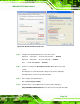
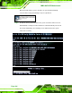
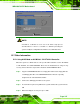
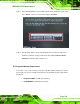
Table Of Contents
- 1 Introduction
- 2 Packing List
- 3 Connectors
- 3.1 Peripheral Interface Connectors
- 3.2 Internal Peripheral Connectors
- 3.2.1 ATX Power Connector
- 3.2.2 Battery Connectors
- 3.2.3 CPU Power Connector
- 3.2.4 DDR3 DIMM Slots
- 3.2.5 Digital I/O Connector
- 3.2.6 Fan Connector (CPU)
- 3.2.7 Fan Connector (System)
- 3.2.8 Front Panel Audio Connector
- 3.2.9 Front Panel Connector
- 3.2.10 I2C Connector
- 3.2.11 Keyboard/Mouse Connector
- 3.2.12 Parallel Port Connector
- 3.2.13 PCI Slots
- 3.2.14 PCIe x1 Slot
- 3.2.15 PCIe x4 Slot
- 3.2.16 PCIe x16 Slot
- 3.2.17 SATA 3Gb/s Drive Connector
- 3.2.18 SATA 6Gb/s Drive Connector
- 3.2.19 Serial Port Connector, RS-422/485
- 3.2.20 Serial Port Connectors, RS-232
- 3.2.21 SMBus Connector
- 3.2.22 SPDIF Connector
- 3.2.23 SPI ROM Connector
- 3.2.24 TPM Connector
- 3.2.25 USB Connectors
- 3.3 External Peripheral Interface Connector Panel
- 4 Installation
- 5 BIOS
- 5.1 Introduction
- 5.2 Main
- 5.3 Advanced
- 5.4 Chipset
- 5.5 Boot
- 5.6 Security
- 5.7 Exit
- 6 Software Drivers
- A BIOS Options
- B One Key Recovery
- C Terminology
- D Digital I/O Interface
- E Watchdog Timer
- F Hazardous Materials Disclosure

IMBA-Q670 ATX Motherboard
Page 189
Step 6: In the following window, select a SATA controller mode used in the system. Then
press <Enter>. The user can now start using the SATA HDD.
Step 7: After pressing <Enter>, the system will get into the recovery tool setup menu.
Continue to follow the setup procedure from Step 4 in Section
B.2.2 Create
Partitions to finish the whole setup process. Step 7:
B.7.2 System Memory Requirement
To be able to access the recovery tool by pressing <F3> while booting up the system,
please make sure to have enough system memory. The minimum memory requirement is
listed below.
Using Award BIOS: 128 MB system memory
Using AMI BIOS: 512 MB system memory.