
Instruction Manual
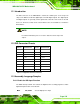
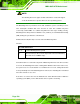
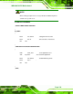
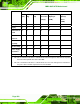
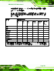
Table Of Contents
- 1 Introduction
- 2 Packing List
- 3 Connectors
- 3.1 Peripheral Interface Connectors
- 3.2 Internal Peripheral Connectors
- 3.2.1 ATX Power Connector
- 3.2.2 Battery Connectors
- 3.2.3 CPU Power Connector
- 3.2.4 DDR3 DIMM Slots
- 3.2.5 Digital I/O Connector
- 3.2.6 Fan Connector (CPU)
- 3.2.7 Fan Connector (System)
- 3.2.8 Front Panel Audio Connector
- 3.2.9 Front Panel Connector
- 3.2.10 I2C Connector
- 3.2.11 Keyboard/Mouse Connector
- 3.2.12 Parallel Port Connector
- 3.2.13 PCI Slots
- 3.2.14 PCIe x1 Slot
- 3.2.15 PCIe x4 Slot
- 3.2.16 PCIe x16 Slot
- 3.2.17 SATA 3Gb/s Drive Connector
- 3.2.18 SATA 6Gb/s Drive Connector
- 3.2.19 Serial Port Connector, RS-422/485
- 3.2.20 Serial Port Connectors, RS-232
- 3.2.21 SMBus Connector
- 3.2.22 SPDIF Connector
- 3.2.23 SPI ROM Connector
- 3.2.24 TPM Connector
- 3.2.25 USB Connectors
- 3.3 External Peripheral Interface Connector Panel
- 4 Installation
- 5 BIOS
- 5.1 Introduction
- 5.2 Main
- 5.3 Advanced
- 5.4 Chipset
- 5.5 Boot
- 5.6 Security
- 5.7 Exit
- 6 Software Drivers
- A BIOS Options
- B One Key Recovery
- C Terminology
- D Digital I/O Interface
- E Watchdog Timer
- F Hazardous Materials Disclosure
IMBA-Q670 ATX Motherboard
Page 195
D.1 Introduction
The DIO connector on the IMBA-Q670 is interfaced to GPIO ports on the Super I/O
chipset. The DIO has both 4-bit digital inputs and 4-bit digital outputs. The digital inputs
and digital outputs are generally control signals that control the on/off circuit of external
devices or TTL devices. Data can be read or written to the selected address to enable the
DIO functions.
NOTE:
For further information, please refer to the datasheet for the Super I/O
chipset.
D.2 DIO Connector Pinouts
PIN NO. DESCRIPTION PIN NO.
DESCRIPTION
1 GND 2 +5V
3 D_IN0 4 D_OUT0
5 D_IN1 6 D_OUT1
7 D_IN2 8 D_OUT2
9 D_IN3 10 D_OUT3
11 D_8IN0 12 D_8OUT0
13 D_8IN1 14 D_8OUT1
15 D_8IN2 16 D_8OUT2
17 D_8IN3 18 D_8OUT3
Table 6-1: Digital I/O Connector Pinouts
D.3 Assembly Language Samples
D.3.1 Enable the DIO Input Function
The BIOS interrupt call INT 15H controls the digital I/O. An assembly program to enable
digital I/O input functions is listed below.
MOV AX, 6F08H
Sets the digital port as input