
Instruction Manual
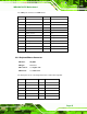
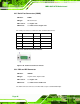
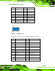
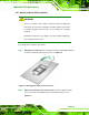
Table Of Contents
- 1 Introduction
- 2 Packing List
- 3 Connectors
- 3.1 Peripheral Interface Connectors
- 3.2 Internal Peripheral Connectors
- 3.2.1 ATX Power Connector
- 3.2.2 Battery Connectors
- 3.2.3 CPU Power Connector
- 3.2.4 DDR3 DIMM Slots
- 3.2.5 Digital I/O Connector
- 3.2.6 Fan Connector (CPU)
- 3.2.7 Fan Connector (System)
- 3.2.8 Front Panel Audio Connector
- 3.2.9 Front Panel Connector
- 3.2.10 I2C Connector
- 3.2.11 Keyboard/Mouse Connector
- 3.2.12 Parallel Port Connector
- 3.2.13 PCI Slots
- 3.2.14 PCIe x1 Slot
- 3.2.15 PCIe x4 Slot
- 3.2.16 PCIe x16 Slot
- 3.2.17 SATA 3Gb/s Drive Connector
- 3.2.18 SATA 6Gb/s Drive Connector
- 3.2.19 Serial Port Connector, RS-422/485
- 3.2.20 Serial Port Connectors, RS-232
- 3.2.21 SMBus Connector
- 3.2.22 SPDIF Connector
- 3.2.23 SPI ROM Connector
- 3.2.24 TPM Connector
- 3.2.25 USB Connectors
- 3.3 External Peripheral Interface Connector Panel
- 4 Installation
- 5 BIOS
- 5.1 Introduction
- 5.2 Main
- 5.3 Advanced
- 5.4 Chipset
- 5.5 Boot
- 5.6 Security
- 5.7 Exit
- 6 Software Drivers
- A BIOS Options
- B One Key Recovery
- C Terminology
- D Digital I/O Interface
- E Watchdog Timer
- F Hazardous Materials Disclosure
IMBA-Q670 ATX Motherboard
Page 47
PIN DESCRIPTION PIN DESCRIPTION
1 CRT_RED 2 CRT_GREEN
3 CRT_BLUE 4 NC
5 GND 6 GND
7 GND 8 GND
9 +5V CRT 10 CRT_PLUG#
11 NC 12 CRT_DDC_DATA
13 CRT_HSYNC 14 CRT_VSYNC
15 CRT_DDC_CLK
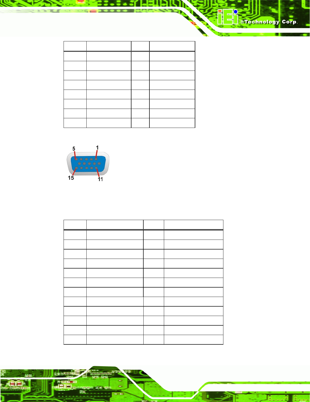
Table 3-29: VGA Connector Pinouts
Figure 3-31: VGA Connector
The DVI connector connects to a monitor that supports DVI video input.
PIN DESCRIPTION PIN DESCRIPTION
1 DVI_TMDS_C_DATA2# 2 DVI_TMDS_C_DATA2
3 GND 4 NC
5 NC 6 DVI_DDC_SCLK
7 DVI_DDC_SDATA 8 NC
9 DVI_TMDS_C_DATA1# 10 DVI_TMDS_C_DATA1
11 GND 12 NC
13 NV 14 +5V_DVI
15 GND 16 DVI_HPD
17 DVI_TMDS_C_DATA0# 18 DVI_TMDS_C_DATA0
19 GND 20 NC
21 NC 22 GND
23 DVI_TMDS_C_CLK 24 DVI_TMDS_C_CLK#
Table 3-30: DVI Connector Pinouts