
Instruction Manual
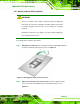
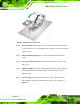
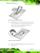
Table Of Contents
- 1 Introduction
- 2 Packing List
- 3 Connectors
- 3.1 Peripheral Interface Connectors
- 3.2 Internal Peripheral Connectors
- 3.2.1 ATX Power Connector
- 3.2.2 Battery Connectors
- 3.2.3 CPU Power Connector
- 3.2.4 DDR3 DIMM Slots
- 3.2.5 Digital I/O Connector
- 3.2.6 Fan Connector (CPU)
- 3.2.7 Fan Connector (System)
- 3.2.8 Front Panel Audio Connector
- 3.2.9 Front Panel Connector
- 3.2.10 I2C Connector
- 3.2.11 Keyboard/Mouse Connector
- 3.2.12 Parallel Port Connector
- 3.2.13 PCI Slots
- 3.2.14 PCIe x1 Slot
- 3.2.15 PCIe x4 Slot
- 3.2.16 PCIe x16 Slot
- 3.2.17 SATA 3Gb/s Drive Connector
- 3.2.18 SATA 6Gb/s Drive Connector
- 3.2.19 Serial Port Connector, RS-422/485
- 3.2.20 Serial Port Connectors, RS-232
- 3.2.21 SMBus Connector
- 3.2.22 SPDIF Connector
- 3.2.23 SPI ROM Connector
- 3.2.24 TPM Connector
- 3.2.25 USB Connectors
- 3.3 External Peripheral Interface Connector Panel
- 4 Installation
- 5 BIOS
- 5.1 Introduction
- 5.2 Main
- 5.3 Advanced
- 5.4 Chipset
- 5.5 Boot
- 5.6 Security
- 5.7 Exit
- 6 Software Drivers
- A BIOS Options
- B One Key Recovery
- C Terminology
- D Digital I/O Interface
- E Watchdog Timer
- F Hazardous Materials Disclosure
IMBA-Q670 ATX Motherboard
Page 51
4.2.1 Socket LGA1155 CPU Installation
WARNING:
CPUs are expensive and sensitive components. When installing the
CPU please be careful not to damage it in anyway. Make sure the CPU
is installed properly and ensure the correct cooling kit is properly
installed.
DO NOT touch the pins at the bottom of the CPU. When handling the
CPU, only hold it on the sides.
To install the CPU, follow the steps below.
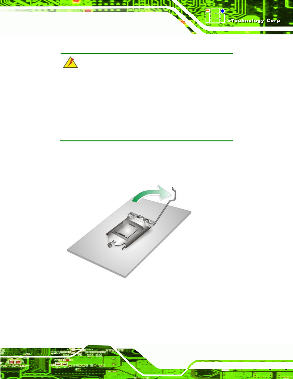
Step 1: Disengage the load lever by pressing the lever down and slightly outward to
clear the retention tab. Fully open the lever. See
Figure 4-1.
Figure 4-1: Disengage the CPU Socket Load Lever
Step 2: Open the socket and remove the protective cover. The black protective
cover can be removed by pulling up on the tab labeled "Remove". See
Figure 4-2.