
Instruction Manual
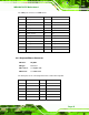
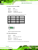
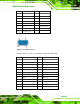
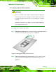
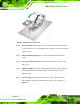
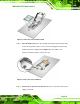
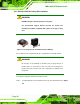
Table Of Contents
- 1 Introduction
- 2 Packing List
- 3 Connectors
- 3.1 Peripheral Interface Connectors
- 3.2 Internal Peripheral Connectors
- 3.2.1 ATX Power Connector
- 3.2.2 Battery Connectors
- 3.2.3 CPU Power Connector
- 3.2.4 DDR3 DIMM Slots
- 3.2.5 Digital I/O Connector
- 3.2.6 Fan Connector (CPU)
- 3.2.7 Fan Connector (System)
- 3.2.8 Front Panel Audio Connector
- 3.2.9 Front Panel Connector
- 3.2.10 I2C Connector
- 3.2.11 Keyboard/Mouse Connector
- 3.2.12 Parallel Port Connector
- 3.2.13 PCI Slots
- 3.2.14 PCIe x1 Slot
- 3.2.15 PCIe x4 Slot
- 3.2.16 PCIe x16 Slot
- 3.2.17 SATA 3Gb/s Drive Connector
- 3.2.18 SATA 6Gb/s Drive Connector
- 3.2.19 Serial Port Connector, RS-422/485
- 3.2.20 Serial Port Connectors, RS-232
- 3.2.21 SMBus Connector
- 3.2.22 SPDIF Connector
- 3.2.23 SPI ROM Connector
- 3.2.24 TPM Connector
- 3.2.25 USB Connectors
- 3.3 External Peripheral Interface Connector Panel
- 4 Installation
- 5 BIOS
- 5.1 Introduction
- 5.2 Main
- 5.3 Advanced
- 5.4 Chipset
- 5.5 Boot
- 5.6 Security
- 5.7 Exit
- 6 Software Drivers
- A BIOS Options
- B One Key Recovery
- C Terminology
- D Digital I/O Interface
- E Watchdog Timer
- F Hazardous Materials Disclosure
IMBA-Q670 ATX Motherboard
Page 54
4.2.2 Socket LGA1155 Cooling Kit Installation
WARNING:
DO NOT attempt to install a push-pin cooling fan.
The pre-installed support bracket prevents the board from
bending and is ONLY compatible with captive screw type cooling
fans.
Figure 4-5: Cooling Kits (CF-1156A-RS and CF-1156B-RS)
The cooling kit can be bought from IEI. The cooling kit has a heatsink and fan.
WARNING:
Do not wipe off (accidentally or otherwise) the pre-sprayed layer of
thermal paste on the bottom of the heat sink. The thermal paste
between the CPU and the heat sink is important for optimum heat
dissipation.
To install the cooling kit, follow the instructions below.
Step 1: A cooling kit bracket is pre-installed on the rear of the motherboard. See
Figure
4-6.