
Instruction Manual
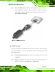
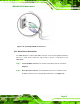
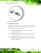
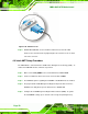
Table Of Contents
- 1 Introduction
- 2 Packing List
- 3 Connectors
- 3.1 Peripheral Interface Connectors
- 3.2 Internal Peripheral Connectors
- 3.2.1 ATX Power Connector
- 3.2.2 Battery Connectors
- 3.2.3 CPU Power Connector
- 3.2.4 DDR3 DIMM Slots
- 3.2.5 Digital I/O Connector
- 3.2.6 Fan Connector (CPU)
- 3.2.7 Fan Connector (System)
- 3.2.8 Front Panel Audio Connector
- 3.2.9 Front Panel Connector
- 3.2.10 I2C Connector
- 3.2.11 Keyboard/Mouse Connector
- 3.2.12 Parallel Port Connector
- 3.2.13 PCI Slots
- 3.2.14 PCIe x1 Slot
- 3.2.15 PCIe x4 Slot
- 3.2.16 PCIe x16 Slot
- 3.2.17 SATA 3Gb/s Drive Connector
- 3.2.18 SATA 6Gb/s Drive Connector
- 3.2.19 Serial Port Connector, RS-422/485
- 3.2.20 Serial Port Connectors, RS-232
- 3.2.21 SMBus Connector
- 3.2.22 SPDIF Connector
- 3.2.23 SPI ROM Connector
- 3.2.24 TPM Connector
- 3.2.25 USB Connectors
- 3.3 External Peripheral Interface Connector Panel
- 4 Installation
- 5 BIOS
- 5.1 Introduction
- 5.2 Main
- 5.3 Advanced
- 5.4 Chipset
- 5.5 Boot
- 5.6 Security
- 5.7 Exit
- 6 Software Drivers
- A BIOS Options
- B One Key Recovery
- C Terminology
- D Digital I/O Interface
- E Watchdog Timer
- F Hazardous Materials Disclosure
IMBA-Q670 ATX Motherboard
Page 65
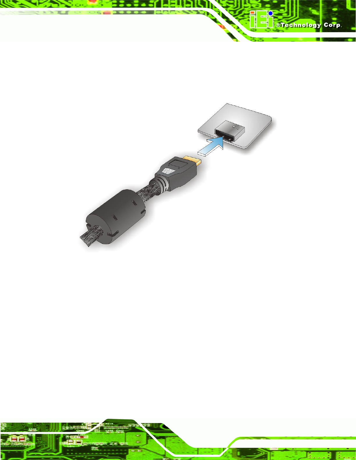
Step 3: Insert the HDMI connector. Gently insert the HDMI connector. The connector
should engage with a gentle push. If the connector does not insert easily, check
again that the connector is aligned correctly, and that the connector is being
inserted with the right way up. Step 0:
Figure 4-15: HDMI Connection
4.5.4 LAN Connection
There are two external RJ-45 LAN connectors. The RJ-45 connectors enable connection
to an external network. To connect a LAN cable with an RJ-45 connector, please follow
the instructions below.
Step 1: Locate the RJ-45 connectors. The locations of the USB connectors are shown
in Chapter 4.
Step 2: Align the connectors. Align the RJ-45 connector on the LAN cable with one of
the RJ-45 connectors on the IMBA-Q670. See
Figure 4-16.