
Instruction Manual
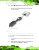
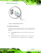
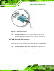
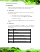
Table Of Contents
- 1 Introduction
- 2 Packing List
- 3 Connectors
- 3.1 Peripheral Interface Connectors
- 3.2 Internal Peripheral Connectors
- 3.2.1 ATX Power Connector
- 3.2.2 Battery Connectors
- 3.2.3 CPU Power Connector
- 3.2.4 DDR3 DIMM Slots
- 3.2.5 Digital I/O Connector
- 3.2.6 Fan Connector (CPU)
- 3.2.7 Fan Connector (System)
- 3.2.8 Front Panel Audio Connector
- 3.2.9 Front Panel Connector
- 3.2.10 I2C Connector
- 3.2.11 Keyboard/Mouse Connector
- 3.2.12 Parallel Port Connector
- 3.2.13 PCI Slots
- 3.2.14 PCIe x1 Slot
- 3.2.15 PCIe x4 Slot
- 3.2.16 PCIe x16 Slot
- 3.2.17 SATA 3Gb/s Drive Connector
- 3.2.18 SATA 6Gb/s Drive Connector
- 3.2.19 Serial Port Connector, RS-422/485
- 3.2.20 Serial Port Connectors, RS-232
- 3.2.21 SMBus Connector
- 3.2.22 SPDIF Connector
- 3.2.23 SPI ROM Connector
- 3.2.24 TPM Connector
- 3.2.25 USB Connectors
- 3.3 External Peripheral Interface Connector Panel
- 4 Installation
- 5 BIOS
- 5.1 Introduction
- 5.2 Main
- 5.3 Advanced
- 5.4 Chipset
- 5.5 Boot
- 5.6 Security
- 5.7 Exit
- 6 Software Drivers
- A BIOS Options
- B One Key Recovery
- C Terminology
- D Digital I/O Interface
- E Watchdog Timer
- F Hazardous Materials Disclosure
IMBA-Q670 ATX Motherboard
Page 68
Figure 4-18: Serial Device Connector
Step 3: Secure the connector. Secure the serial device connector to the external
interface by tightening the two retention screws on either side of the connector.
Step 0:
4.5.7 USB Connection (Dual Connector)
The external USB Series "A" receptacle connectors provide easier and quicker access to
external USB devices. Follow the steps below to connect USB devices to the IMBA-Q670.
Step 1: Locate the USB Series "A" receptacle connectors. The location of the USB
Series "A" receptacle connectors are shown in Chapter 3.
Step 2: Insert a USB Series "A" plug. Insert the USB Series "A" plug of a device into
the USB Series "A" receptacle on the external peripheral interface. See
Figure 4-19.