IOWA-LX-600 Half-size CPU Card )zIOWA-LX-600 CPU Card IEI Technology Corp. MODEL: IOWA-LX-600 Half-size ISA CPU Card with on-board AMD Geode LX 600 VGA, LAN, USB 2.0, CF, COM, Parallel Port and Audio RoHS Compliant User Manual Page I Rev. 1.
IOWA-LX-600 Half-size CPU Card Revision Date Version Changes 31 March, 2011 1.
IOWA-LX-600 Half-size CPU Card Copyright COPYRIGHT NOTICE The information in this document is subject to change without prior notice in order to improve reliability, design and function and does not represent a commitment on the part of the manufacturer. In no event will the manufacturer be liable for direct, indirect, special, incidental, or consequential damages arising out of the use or inability to use the product or documentation, even if advised of the possibility of such damages.
IOWA-LX-600 Half-size CPU Card Table of Contents 1 INTRODUCTION.......................................................................................................... 1 1.1 INTRODUCTION........................................................................................................... 2 1.2 MODEL VARIATIONS ................................................................................................... 2 1.3 BENEFITS .............................................................................
IOWA-LX-600 Half-size CPU Card 3.2.10 IDE Connector (40-pin)................................................................................. 26 3.2.11 Infrared Interface Connector (5-pin) ............................................................. 27 3.2.12 Keyboard/Mouse Connector .......................................................................... 28 3.2.13 Parallel Port Connector ................................................................................ 29 3.2.14 Power Connector ..........
IOWA-LX-600 Half-size CPU Card 4.8.2 ATA Flat Cable Connection ............................................................................. 54 4.8.3 USB Cable........................................................................................................ 55 4.9 EXTERNAL PERIPHERAL INTERFACE CONNECTION ................................................... 56 4.9.1 LAN Connection (Single Connector) ............................................................... 56 4.9.2 PS/2 Y-Cable Connection.........
IOWA-LX-600 Half-size CPU Card B.2.2 Create Partitions ............................................................................................ 111 B.2.3 Install Operating System, Drivers and Applications ......................................114 B.2.4 Build-up Recovery Partition...........................................................................115 B.2.5 Create Factory Default Image........................................................................117 B.3 SETUP PROCEDURE FOR LINUX .........
IOWA-LX-600 Half-size CPU Card List of Figures Figure 1-1: IOWA-LX-600 ...............................................................................................................2 Figure 1-2: Connectors ..................................................................................................................4 Figure 1-3: IOWA-LX-600 Dimensions (mm) ................................................................................5 Figure 1-4: Data Flow Block Diagram ..............................
IOWA-LX-600 Half-size CPU Card Figure 4-4: AT/ATX Power Select Jumper Location..................................................................48 Figure 4-5: CompactFlash® Setup Jumper Location ...............................................................49 Figure 4-6: COM 3 Function Select Jumper Location...............................................................50 Figure 4-7: LVDS Voltage Selection Jumper Locations ...........................................................
IOWA-LX-600 Half-size CPU Card Figure B-22: Partitions for Linux.............................................................................................. 123 Figure B-23: System Configuration for Linux......................................................................... 124 Figure B-24: Access menu.lst in Linux (Text Mode) .............................................................. 124 Figure B-25: Recovery Tool Menu ...............................................................................
IOWA-LX-600 Half-size CPU Card List of Tables Table 1-1: IOWA-LX-600 Model Variations ...................................................................................3 Table 1-2: Technical Specifications..............................................................................................8 Table 3-1: Peripheral Interface Connectors ...............................................................................16 Table 3-2: Rear Panel Connectors ...................................................
IOWA-LX-600 Half-size CPU Card Table 4-4: COM 3 Function Select Jumper Settings .................................................................49 Table 4-5: LVDS Voltage Selection Jumper Settings................................................................50 Table 4-6: LCD Clock Select Jumper Settings...........................................................................51 Table 5-1: BIOS Navigation Keys ...............................................................................................
IOWA-LX-600 Half-size CPU Card List of BIOS Menus BIOS Menu 1: Award BIOS Setup Utility ....................................................................................64 BIOS Menu 2: Standard CMOS Features....................................................................................67 BIOS Menu 3: IDE Channel Master..............................................................................................69 BIOS Menu 4: IDE Channel Master.......................................................
IOWA-LX-600 Half-size CPU Card Chapter 1 1 Introduction Page 1
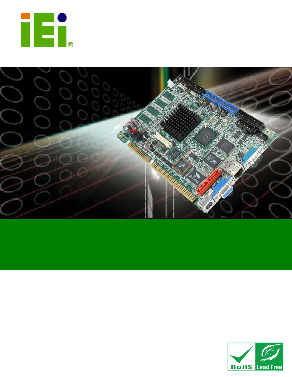
IOWA-LX-600 Half-size CPU Card 1.1 Introduction Figure 1-1: IOWA-LX-600 The IOWA-LX-600 is an AMD Geode™ LX based based half-size ISA CPU card. The IOWA-LX-600 has a Front Side Bus (FSB) of 366 MHz, 128 MB of RAM on-board and is upgradeable with a further 512 MB of SDRAM. Multiple input/output options include VGA and 24-bit TTL for video output, a parallel port, two serial ports, an infrared port and 10/100BASE-T Ethernet. The IOWA-LX-600 supports up to two IDE drives and one floppy drive.
IOWA-LX-600 Half-size CPU Card MODEL IOWA-LX-600 IOWA-LX-600S CPU Speed 366 MHz 366 MHz Onboard Memory 128 MB 128 MB SATA No Yes Table 1-1: IOWA-LX-600 Model Variations 1.
IOWA-LX-600 Half-size CPU Card 1.5 Connectors The connectors on the IOWA-LX-600 are shown in the figure below.
IOWA-LX-600 Half-size CPU Card 1.6 Dimensions The dimensions of the board are listed below: Length: 184.99 mm Width: 122.
IOWA-LX-600 Half-size CPU Card 1.7 Data Flow Figure 1-4 shows the data flow between the two on-board chipsets and other components 5 installed on the motherboard and described in the following sections of this chapter.
IOWA-LX-600 Half-size CPU Card 1.8 Technical Specifications IOWA-LX-600 technical specifications are listed in table below. Specification IOWA-LX-600 Form Factor Half-size CPU Supported AMD Geode LX 600 with a 366 MHz FSB and 128KB L2 cache Express Chipset AMD Geode CS5536 Memory On-board 128 MB 200/266 MHz DDR SDRAM One 200-pin SO-DIMM sockets support 200/266 MHz DDR SDRAM SO-DIMMs (system max.
IOWA-LX-600 Half-size CPU Card Specification IOWA-LX-600 Serial Ports Two RS-232 One RS-422/485 via pin header USB 2.0/1.
IOWA-LX-600 Half-size CPU Card Chapter 2 2 Unpacking Page 9
IOWA-LX-600 Half-size CPU Card 2.1 Anti-static Precautions WARNING! Static electricity can destroy certain electronics. Make sure to follow the ESD precautions to prevent damage to the product, and injury to the user. Make sure to adhere to the following guidelines: Wear an anti-static wristband: Wearing an anti-static wristband can prevent electrostatic discharge. Self-grounding: Touch a grounded conductor every few minutes to discharge any excess static buildup.
IOWA-LX-600 Half-size CPU Card 2.3 Packing List NOTE: If any of the components listed in the checklist below are missing, do not proceed with the installation. Contact the IEI reseller or vendor the IOWA-LX-600 was purchased from or contact an IEI sales representative directly by sending an email to sales@iei.com.tw.
IOWA-LX-600 Half-size CPU Card 1 Utility CD 1 Quick Installation Guide 2.3.
IOWA-LX-600 Half-size CPU Card Chapter 3 3 Connectors Page 13
IOWA-LX-600 Half-size CPU Card 3.1 Peripheral Interface Connectors This chapter details all the jumpers and connectors. 3.1.1 IOWA-LX-600 Layout The figures below show all the connectors and jumpers.
IOWA-LX-600 Half-size CPU Card 3.1.2 Peripheral Interface Connectors The table below lists all the connectors on the board.
IOWA-LX-600 Half-size CPU Card USB connector 8-pin header CN13 VCC ISA power connector 3-pin header CN1 Table 3-1: Peripheral Interface Connectors 3.1.3 External Interface Panel Connectors The table below lists the connectors on the external I/O panel. Connector Type Label Ethernet connector RJ-45 CN22 Keyboard and mouse connector PS/2 CN24 Serial port DB-9 male CN21 VGA connector DB-15 female CN23 Table 3-2: Rear Panel Connectors 3.
IOWA-LX-600 Half-size CPU Card Figure 3-2: ATX Power Supply Enable Connector Location PIN DESCRIPTION 1 GND 2 PS-ON 3 +5V Standby Table 3-3: ATX Power Supply Enable Connector Pinouts 3.2.2 Audio Connector (10-pin) CN Label: CN19 CN Type: 10-pin box header (2x5) CN Location: See Figure 3-3 CN Pinouts: See Table 3-4 5 5 The 10-pin audio connector is connected to external audio devices including speakers and microphones for the input and output of audio signals to and from the system.
IOWA-LX-600 Half-size CPU Card Figure 3-3: Audio Connector Pinouts (10-pin) PIN DESCRIPTION PIN DESCRIPTION 1 Line out (Right) 2 Line in (Right) 3 GND 4 GND 5 Line out (Left) 6 Line in (Left) 7 GND 8 GND 9 MIC1 in 10 MIC2 in Table 3-4: Audio Connector Pinouts (10-pin) 3.2.
IOWA-LX-600 Half-size CPU Card Figure 3-4: Backlight Inverter Connector Pinout Locations PIN DESCRIPTION 1 GND 2 GND 3 +12V 4 GND 5 LCD Enable Table 3-5: Backlight Inverter Connector Pinouts 3.2.4 Battery Connector CN Label: CN14 CN Type: 2-pin wafer (1x2) CN Location: See Figure 3-5 CN Pinouts: See Table 3-6 5 5 The battery connector is connected to a backup battery.
IOWA-LX-600 Half-size CPU Card Figure 3-5: Battery Connector Location PIN NO. DESCRIPTION 1 Battery+ 2 Ground Table 3-6: Battery Connector Pinouts 3.2.5 CompactFlash® Socket CN Label: CN28 (solder side) CN Type: 50-pin CF Type II slot CN Location: See Figure 3-6 CN Pinouts: See Table 3-7 5 5 A CF Type I or Type II memory card can be inserted to the CF socket on the solder side of the IOWA-LX-600.
IOWA-LX-600 Half-size CPU Card Figure 3-6: CF Card Socket Location PIN DESCRIPTION PIN DESCRIPTION 1 GROUND 26 CFD2 2 SDD3 27 SDD11 3 SDD4 28 SDD12 4 SDD5 29 SDD13 5 SDD6 30 SDD14 6 SDD7 31 SDD15 7 SDCS1# 32 SDCS3# 8 GROUND 33 N/C 9 GROUND 34 SDIOR# 10 GROUND 35 SDIOW# 11 GROUND 36 VCC 12 GROUND 37 IRQ15 13 VCC 38 VCC 14 GROUND 39 MASTER/SLAVE 15 GROUND 40 N/C 16 GROUND 41 RESET# 17 GROUND 42 SIORDY 18 SDA2 43 SDDREQ 19 SDA1 44
IOWA-LX-600 Half-size CPU Card PIN DESCRIPTION PIN DESCRIPTION 23 SDD2 48 SDD9 24 N/C 49 SDD10 25 CFD1 50 GROUND Table 3-7: CF Card Socket Pinouts 3.2.6 Digital Input/Output (DIO) Connector CN Label: CN16 CN Type: 10-pin header (2x5) CN Location: See Figure 3-7 CN Pinouts: See Table 3-8 5 5 The digital input/output connector is managed through a Super I/O chip. The DIO connector pins are user programmable.
IOWA-LX-600 Half-size CPU Card 5 Output 2 6 Output 3 7 Input 0 8 Input 1 9 Input 2 10 Input 3 Table 3-8: DIO Connector Pinouts 3.2.7 Fan Connector (+5V) CN Label: CN8 CN Type: 3-pin wafer CN Location: See Figure 3-8 CN Pinouts: See Table 3-9 5 5 The cooling fan connector provides a 5V, 500mA current to a system cooling fan. The connector has a "rotation" pin to get rotation signals from fans. Please note that only specified fans can issue the rotation signals.
IOWA-LX-600 Half-size CPU Card 3.2.8 Floppy Disk Connector CN Label: CN9 CN Type: 34-pin header (2x17) CN Location: See Figure 3-9 CN Pinouts: See Table 3-10 5 5 The floppy disk connector is connected to a floppy disk drive.
IOWA-LX-600 Half-size CPU Card PIN DESCRIPTION PIN DESCRIPTION 19 GROUND 20 STEP# 21 GROUND 22 WDATA# 23 GROUND 24 WGATE# 25 GROUND 26 TRK0# 27 GROUND 28 WP# 29 N/C 30 RDATA# 31 GROUND 32 HDSEL# 33 N/C 34 DSKCHG# Table 3-10: FDD Connector Pinouts 3.2.
IOWA-LX-600 Half-size CPU Card PIN DESCRIPTION PIN DESCRIPTION 1 PWRBTN 2 +5V 3 GROUND 4 GROUND 5 +5V 6 RESET 7 HDDLED- 8 GROUND Table 3-11: Front Panel Connector Pinouts 3.2.10 IDE Connector (40-pin) CN Label: CN11 CN Type: 40-pin box header (2x20) CN Location: See Figure 3-11 CN Pinouts: See Table 3-12 5 5 One 40-pin IDE device connector on the IOWA-LX-600 supports connectivity to two hard disk drives.
IOWA-LX-600 Half-size CPU Card PIN DESCRIPTION PIN DESCRIPTION 1 RESET# 2 GROUND 3 DATA 7 4 DATA 8 5 DATA 6 6 DATA 9 7 DATA 5 8 DATA 10 9 DATA 4 10 DATA 11 11 DATA 3 12 DATA 12 13 DATA 2 14 DATA 13 15 DATA 1 16 DATA 14 17 DATA 0 18 DATA 15 19 GROUND 20 N/C 21 DRQ 22 GROUND 23 IOW# 24 GROUND 25 IOR# 26 GROUND 27 CHRDY 28 (PULL LOW TO GND) 29 DACK# 30 GROUND 31 INTERRUPT 32 N/C 33 SA1 34 N/C 35 SA0 36 SA2 37 HDC CS0# 38 HDC CS1# 3
IOWA-LX-600 Half-size CPU Card Figure 3-12: Infrared Connector Pinout Locations PIN DESCRIPTION 1 VCC 2 NC 3 IR-RX 4 GND 5 IR-TX Table 3-13: Infrared Connector Pinouts 3.2.12 Keyboard/Mouse Connector CN Label: CN25 CN Type: 6-pin wafer (1x6) CN Location: See Figure 3-13 CN Pinouts: See Table 3-14 6 6 The keyboard and mouse connector can be connected to a standard PS/2 cable or PS/2 Y-cable to add keyboard and mouse functionality to the system.
IOWA-LX-600 Half-size CPU Card Figure 3-13: Keyboard/Mouse Connector Location PIN DESCRIPTION 1 +5V 2 Mouse Data 3 Mouse Clock 4 Keyboard Data 5 Keyboard Clock 6 Ground Table 3-14: Keyboard/Mouse Connector Pinouts 3.2.13 Parallel Port Connector CN Label: CN17 CN Type: 26-pin box header CN Location: See Figure 3-14 CN Pinouts: See Table 3-15 6 6 The 26-pin parallel port connector connects to a parallel port connector interface or some other parallel port device such as a printer.
IOWA-LX-600 Half-size CPU Card Figure 3-14: Parallel Port Connector Location PIN DESCRIPTION PIN DESCRIPTION 1 STROBE# 2 AUTO FORM FEED # 3 DATA 0 4 ERROR# 5 DATA 1 6 INITIALIZE 7 DATA 2 8 PRINTER SELECT LN# 9 DATA 3 10 GROUND 11 DATA 4 12 GROUND 13 DATA 5 14 GROUND 15 DATA 6 16 GROUND 17 DATA 7 18 GROUND 19 ACKNOWLEDGE 20 GROUND 21 BUSY 22 GROUND 23 PAPER EMPTY 24 GROUND 25 PRINTER SELECT 26 N/C Table 3-15: Parallel Port Connector Pinouts 3.2.
IOWA-LX-600 Half-size CPU Card CN Location: See Figure 3-15 CN Pinouts: See Table 3-16 6 6 The 4-pin power connector is connected to a power supply. Figure 3-15: Power Connector Location PIN DESCRIPTION 1 +5V 2 GND 3 GND 4 +12V Table 3-16: Power Connector Pinouts 3.2.15 SATA Drive Connectors (Optional) CN Label: CN26 and CN27 CN Type: 7-pin SATA drive connectors CN Location: See Figure 3-16 CN Pinouts: See Table 3-17 6 6 The SATA connectors connect to SATA 1.
IOWA-LX-600 Half-size CPU Card Figure 3-16: SATA Drive Connector Locations PIN DESCRIPTION 1 GND 2 TX+ 3 TX- 4 GND 5 RX- 6 RX+ 7 GND Table 3-17: SATA Drive Connector Pinouts 3.2.16 Serial Port Connector (RS-232/422/485) CN Label: CN18 CN Type: 14-pin box header (2x7) CN Location: See Figure 3-17 CN Pinouts: See Table 3-18 6 6 This connector provides RS-232 communications via pin 1 ~ pin 10 as COM2.
IOWA-LX-600 Half-size CPU Card Figure 3-17: Internal Serial Port Connector Pinout Locations PIN DESCRIPTION PIN DESCRIPTION 1 Data Carrier Direct (DCD) 2 Data Set Ready (DSR) 3 Receive Data (RXD) 4 Request To Send (RTS) 5 Transmit Data (TXD) 6 Clear To Send (CTS) 7 Data Terminal Ready (DTR) 8 Ring Indicator (RI) 9 Ground (GND) 10 Ground (GND) 11 TxD485+ 12 TxD485# 13 RxD485+ 14 RxD485# Table 3-18: Internal Serial Port Connector Pinouts 3.2.
IOWA-LX-600 Half-size CPU Card Figure 3-18: TFT LCD Connector Pinout Locations PIN DESCRIPTION PIN DESCRIPTION 1 VCD_VCC 2 VCD_VCC 3 GROUND 4 GROUND 5 VCD_VCC 6 VCD_VCC 7 I_SDATA 8 GROUND 9 TFT_B0 10 TFT_B1 11 TFT_B2 12 TFT_B3 13 TFT_B4 14 TFT_B5 15 TFT_B6 16 TFT_B7 17 TFT_G0 18 TFT_G1 19 TFT_G2 20 TFT_G3 21 TFT_G4 22 TFT_G5 23 TFT_G6 24 TFT_G7 25 TFT_R0 26 TFT_R1 27 TFT_R2 28 TFT_R3 29 TFT_R4 30 TFT_R5 31 TFT_R6 32 TFT_R7 33 GROUND 34
IOWA-LX-600 Half-size CPU Card 3.2.18 Internal USB Connectors CN Label: CN12 and CN13 CN Type: 8-pin header (2x4) CN Location: See Figure 3-19 CN Pinouts: See Table 3-20 6 6 The 2x4 USB pin connectors each provide connectivity to two USB 2.0 ports. Each USB connector can support two USB devices. The USB ports are used for I/O bus expansion.
IOWA-LX-600 Half-size CPU Card 3.2.19 -VCC Power Connector CN Label: CN1 CN Type: 3-pin header (1x3) CN Location: See Figure 3-19 CN Pinouts: See Table 3-20 6 6 The –VCC power connector provides –5V and –12V power to legacy expansion ISA devices installed on the backplane. The power supply is connected to the –VCC power connecter and transmitted to the ISA devices through the backplane.
IOWA-LX-600 Half-size CPU Card 3.3 External Peripheral Interface Connectors The IOWA-LX-600 external peripheral interface connectors are listed below and shown in Figure 3-21: 6 1 x PS/2 Keyboard/Mouse connector 1 x RJ-45 Ethernet connector 1 x Serial communications port 1 x VGA port Figure 3-21: IOWA-LX-600 On-board External Interface Connectors 3.3.
IOWA-LX-600 Half-size CPU Card PIN DESCRIPTION PIN DESCRIPTION 1 KEYBBOARD DATA 2 MOUSE DATA 3 GND 4 GND 5 KEYBOARD CLOCK 6 MOUSE CLOCK Table 3-22: PS/2 Connector Pinouts 3.3.2 RJ-45 Ethernet Connector CN Label: CN22 CN Type: RJ-45 CN Location: See Figure 3-21 CN Pinouts: See Table 3-23 6 6 The RJ-45 Ethernet connector on the IOWA-LX-600 provides connectivity to a 10/100 megabit Ethernet connection between the IOWA-LX-600 and a Local Area Network (LAN) through a network hub.
IOWA-LX-600 Half-size CPU Card Figure 3-23: RJ-45 Connector The RJ-45 Ethernet connector has two status LEDs, one green and one yellow. The green LED indicates activity on the port and the yellow LED indicates the port is linked. SPEED LED LINK LED Status Description GREEN ON: 100MB Status Description YELLOW OFF: 10MB ON: Linked Flashing: Activity Table 3-24: J7 Connector LEDs 3.3.
IOWA-LX-600 Half-size CPU Card Figure 3-24: COM1 Pinout Locations 3.3.4 VGA Connector CN Label: CN23 CN Type: DB-15 CN Location: See Figure 3-21 CN Pinouts: See Table 3-26 6 6 The standard 15-pin female DB-15 VGA connector connects to a CRT or LCD monitor directly.
IOWA-LX-600 Half-size CPU Card Chapter 4 4 Installation Page 41
IOWA-LX-600 Half-size CPU Card 4.1 Anti-static Precautions WARNING: Failure to take ESD precautions during the installation of the IOWA-LX-600 may result in permanent damage to the IOWA-LX-600 and severe injury to the user. Electrostatic discharge (ESD) can cause serious damage to electronic components, including the IOWA-LX-600. Dry climates are especially susceptible to ESD.
IOWA-LX-600 Half-size CPU Card 4.2 Installation Considerations NOTE: The following installation notices and installation considerations should be read and understood before the IOWA-LX-600 is installed. All installation notices pertaining to the installation of the IOWA-LX-600 should be strictly adhered to. Failing to adhere to these precautions may lead to severe damage of the IOWA-LX-600 and injury to the person installing the motherboard. 4.2.
IOWA-LX-600 Half-size CPU Card o When working with the IOWA-LX-600, make sure that it is disconnected from all power supplies and that no electricity is being fed into the system. Before and during the installation of the IOWA-LX-600 DO NOT: Remove any of the stickers on the PCB board. These stickers are required for warranty validation. Use the product before verifying all the cables and power connectors are properly connected.
IOWA-LX-600 Half-size CPU Card Figure 4-1: SO-DIMM Installation Step 1: Locate the SO-DIMM socket. Place the IOWA-LX-600 on an anti-static pad with the solder side facing up. Step 2: Align the SO-DIMM with the socket. The SO-DIMM must be oriented in such a way that the notch in the middle of the SO-DIMM must be aligned with the plastic bridge in the socket. Step 3: Insert the SO-DIMM. Push the SO-DIMM chip into the socket at an angle. (See Figure 4-1) 6 Step 4: Open the SO-DIMM socket arms.
IOWA-LX-600 Half-size CPU Card To install the a CF card (Type I or Type II) onto the IOWA-LX-600, please follow the steps below: Step 1: Locate the CF card socket. Place the IOWA-LX-600 on an anti-static pad with the solder side facing up. Locate the CF card on the solder side. Step 2: Align the CF card. Make sure the CF card is properly aligned with the CF socket. Step 3: Insert the CF card. Gently insert the CF card into the socket making sure the socket pins are properly inserted into the socket.
IOWA-LX-600 Half-size CPU Card 4.6 Jumper Settings NOTE: A jumper is a metal bridge used to close an electrical circuit. It consists of two or three metal pins and a small metal clip (often protected by a plastic cover) that slides over the pins to connect them. To CLOSE/SHORT a jumper means connecting the pins of the jumper with the plastic clip and to OPEN a jumper means removing the Figure 4-3: Jumper Locations plastic clip from a jumper.
IOWA-LX-600 Half-size CPU Card The AT/ATX Power Select jumper specifies the systems power mode as AT or ATX. AT/ATX Power Select jumper settings are shown in Table 4-2. 6 Setting Description Short Use AT power (Default) Open Use ATX power Table 4-2: AT/ATX Power Select Jumper Settings The location of the AT/ATX Power Select jumper is shown in Figure 4-4 below. 6 Figure 4-4: AT/ATX Power Select Jumper Location 4.6.
IOWA-LX-600 Half-size CPU Card Setting Description Short 1-2 Slave Short 2-3 Master Table 4-3: CompactFlash® Setup Jumper Settings Figure 4-5: CompactFlash® Setup Jumper Location 4.6.3 COM 3 Function Select Jumper Label: JP3 Jumper Type: 3-pin header Jumper Settings: See Table 4-4 Jumper Location: See Figure 4-6 6 6 The COM 3 Function Select jumper sets the communication protocol used by the third serial communications port (COM 3) as RS-422 or RS-485.
IOWA-LX-600 Half-size CPU Card Figure 4-6: COM 3 Function Select Jumper Location 4.6.4 LCD Voltage Select WARNING: Incorrect voltages can destroy the LCD panel. Make sure to select a voltage that matches the voltage required by the LCD panel. Jumper Label: JP5 Jumper Type: 3-pin header Jumper Settings: See Table 4-5 Jumper Location: See Figure 4-7 6 6 The LCD voltage selection jumper sets the voltage of the power supplied to the LCD panel. Setting Description Short 1-2 +3.
IOWA-LX-600 Half-size CPU Card Figure 4-7: LVDS Voltage Selection Jumper Locations 4.6.5 LCD Clock Select Jumper Jumper Label: JP6 Jumper Type: 3-pin header Jumper Settings: See Table 4-1 Jumper Location: See Figure 4-8 6 6 This jumper inverts the LCD clock of the LCD connector (CN10).
IOWA-LX-600 Half-size CPU Card 4.7 Chassis Installation 4.7.1 Airflow WARNING: Airflow is critical to the cooling of the CPU and other onboard components. The chassis in which the IOWA-LX-600 must have air vents to allow cool air to move into the system and hot air to move out. The IOWA-LX-600 must be installed in a chassis with ventilation holes on the sides allowing airflow to travel through the heat sink surface.
IOWA-LX-600 Half-size CPU Card 4.8 Internal Peripheral Device Connections This section outlines the installation of peripheral devices to the onboard connectors 4.8.1 5.1 Channel Audio Kit Installation The audio kit attaches to the audio connector. The audio kit provides 5.1 channel audio. To install the audio kit, please refer to the steps below: Step 1: Connect the cable to the audio kit. Connect the included cable to the audio kit. Make sure pin 1 aligns with the marked pin.
IOWA-LX-600 Half-size CPU Card 4.8.2 ATA Flat Cable Connection The IDE cable can connect to one or two IDE devices. To connect the IDE devices, follow the steps below. Step 1: Locate the IDE connector. Locate the IDE connector on the board. Step 2: Insert the connector. Connect the IDE cable connector to the on-board connector. See Figure 4-10. A key on the front of the cable connector ensures it 6 can only be inserted in one direction.
IOWA-LX-600 Half-size CPU Card 4.8.3 USB Cable The IOWA-LX-600 is shipped with a dual port USB 2.0 cable. To connect the USB cable connector, please follow the steps below. Step 1: Locate the connectors. The locations of the USB connectors are shown in Chapter 3. WARNING: If the USB pins are not properly aligned, the USB device can burn out. Step 2: Align the connectors. The cable has two connectors. Correctly align pin 1on each cable connector with pin 1 on the IOWA-LX-600 USB connector.
IOWA-LX-600 Half-size CPU Card Step 4: Attach the bracket to the chassis. The USB 2.0 connectors are attached to a bracket. To secure the bracket to the chassis please refer to the installation instructions that came with the chassis.Step 0: 4.9 External Peripheral Interface Connection Devices can be connected to the external connectors. To install external devices, follow the directions in the subsections below. 4.9.1 LAN Connection (Single Connector) There is one external RJ-45 LAN connector.
IOWA-LX-600 Half-size CPU Card Step 3: Insert the LAN cable RJ-45 connector. Once aligned, gently insert the LAN cable RJ-45 connector into the on-board RJ-45 connector. Step 0: 4.9.2 PS/2 Y-Cable Connection The IOWA-LX-600 has a PS/2 connector on the external peripheral interface panel. The dual PS/2 connector is connected to the PS/2 Y-cable that came with the IOWA-LX-600. One of the PS/2 cables is connected to a keyboard and the other to a mouse to the system.
IOWA-LX-600 Half-size CPU Card distinguished from each other by looking at the small graphic at the top of the connector. Step 0: 4.9.3 Serial Device Connection The IOWA-LX-600 has a single female DB-9 connector on the external peripheral interface panel for a serial device. Follow the steps below to connect a serial device to the IOWA-LX-600. Step 1: Locate the DB-9 connector. The location of the DB-9 connector is shown in Chapter 3. Step 2: Insert the serial connector.
IOWA-LX-600 Half-size CPU Card Step 3: Secure the connector. Secure the serial device connector to the external interface by tightening the two retention screws on either side of the connector. Step 0: 4.9.4 VGA Monitor Connection The IOWA-LX-600 has a single female DB-15 connector on the external peripheral interface panel. The DB-15 connector is connected to a CRT or VGA monitor. To connect a monitor to the IOWA-LX-600, please follow the instructions below. Step 1: Locate the female DB-15 connector.
IOWA-LX-600 Half-size CPU Card Step 4: Secure the connector. Secure the DB-15 VGA connector from the VGA monitor to the external interface by tightening the two retention screws on either side of the connector. Step 0: 4.10 Software Installation All the drivers for the IOWA-LX-600 are on the CD that came with the system. To install the drivers, please follow the steps below. Step 1: Insert the CD into a CD drive connected to the system.
IOWA-LX-600 Half-size CPU Card Step 3: Click IOWA-LX. Step 4: A new screen with a list of available drivers appears (Figure 4-17). 6 Figure 4-17: Available Drivers Step 5: Install all of the necessary drivers in this menu.
IOWA-LX-600 Half-size CPU Card Chapter 5 5 BIOS Screens Page 62
IOWA-LX-600 Half-size CPU Card 5.1 Introduction The BIOS is programmed onto the BIOS chip. The BIOS setup program allows changes to certain system settings. This chapter outlines the options that can be changed. 5.1.1 Starting Setup The UEFI BIOS is activated when the computer is turned on. The setup program can be activated in one of two ways. 1. Press the DELETE key as soon as the system is turned on or 2. Press the DELETE key when the “Press Del to enter SETUP” message appears on the screen.
IOWA-LX-600 Half-size CPU Card F10 Save changes and Exit BIOS Table 5-1: BIOS Navigation Keys 5.1.3 Getting Help When F1 is pressed a small help window describing the appropriate keys to use and the possible selections for the highlighted item appears. To exit the Help Window press ESC or the F1 key again. 5.1.4 Unable to Reboot After Configuration Changes If the system cannot be booted after changes are made, restore the CMOS defaults. Refer to Section 3.2.4 for more information. 6 5.1.
IOWA-LX-600 Half-size CPU Card NOTE: The following sections will completely describe the menus listed below and the configuration options available to users. The following menu options are seen in BIOS Menu 1. 6 Standard CMOS Features: Changes the basic system configuration. Advanced BIOS Features: Changes the advanced system settings. Advanced Chipset Features: Changes the chipset configuration features. Integrated Peripherals: Changes the settings for integrated peripherals.
IOWA-LX-600 Half-size CPU Card Set User Password Use the Set User Password option to set the supervisor password. By default no user password is set. To install a user password, select this field and enter the password. After this option is selected, a red dialogue box appears with “Enter Password: ”. Type the password and press ENTER. Retype the original password into the “Confirm Password: ” dialogue box and press ENTER.
IOWA-LX-600 Half-size CPU Card Phoenix - AwardBIOS CMOS Setup Utility Standard CMOS Features Date (mm:dd:yy) Time (hh:mm:ss) Mon, Jan 1 2007 0:29:49 Item Help Menu Level > > IDE Primary Master > IDE Primary Slave Drive A [ None] [ None] [1.44M, 3.5 in.
IOWA-LX-600 Half-size CPU Card Drive A [None] Use the Drive A/B configuration to specify the floppy drive type installed in the system. The floppy drive configuration options are: None 360K, 5.25 in. 1.2M, 5.25 in. 720K, 3.5 in. 1.44M, 3.5in (Default) 2.88M, 3.5 in. Base Memory: The Base Memory is NOT user configurable. The POST determines the amount of base (or conventional) memory installed in the system.
IOWA-LX-600 Half-size CPU Card Phoenix - AwardBIOS CMOS Setup Utility IDE Primary Master IDE HDD Auto-Detection [Press Enter] IDE Primary Master Access Mode [Auto] [Auto] Item Help Menu Level > Capacity 0 MB Cylinder Header Precomp Landing Zone Sector 0 0 0 0 0 To auto-detect the HDD’s size, head...
IOWA-LX-600 Half-size CPU Card device on the IDE channel in BIOS. Access Mode [Auto] The Access Mode option can only be configured if the BIOS configuration option is set to either Manual or Auto. Use the Access Mode option to determine the hard disk BIOS translation modes. Most systems now use hard drives with large capacities and therefore either the LBA translation mode or auto mode should be selected. Select this mode if the HDD capacity is less than CHS 504MB.
IOWA-LX-600 Half-size CPU Card Landing Zone The Landing Zone specification indicates where the disk head will park itself after the system powers off. Sector The Sector specification indicates how many logical sectors the HDD has been divided into. 5.3 Advanced BIOS Features Use the Advanced BIOS Features menu (BIOS Menu 4) to configure the CPU and 6 peripheral device configuration options.
IOWA-LX-600 Half-size CPU Card Virus Warning [Disabled] NOTE: Many disk diagnostic programs can cause the above warning message to appear when the program attempts to access the boot sector table. If you are running such a program, it is recommended that the virus protection function be disabled beforehand. Use the Virus Warning option to enable BIOS to monitor the boot sector and partition table of the HDD for any attempted modification.
IOWA-LX-600 Half-size CPU Card through the LAN. SATA Boot ROM Control [Disabled] Use the SATA Boot ROM Control option to configure SATA IDE use in DOS mode. Disabled (Default) Enabled Disables SATA IDE use in DOS mode. Enables SATA IDE use in DOS mode. Boot Device Use the Boot Device options to select the order of the devices the system boots from.
IOWA-LX-600 Half-size CPU Card Boot Other Device [Enabled] Use the Boot Other Device option to determine whether the system uses a second or third boot device if the first boot device is not found. The system does not look for second and third boot Disabled devices if the first one is not found. Enabled (Default) The system looks for second and third boot devices if the first one is not found.
IOWA-LX-600 Half-size CPU Card The keyboard controller does the switching. Normal Fast (Default) The chipset does the switching. Typematic Rate Setting [Disabled] Use the Typematic Rate Setting configuration option to specify if only one character is allowed to appear on the screen if a key is continuously held down. When this option is enabled, the BIOS reports as before, but it then waits a moment, and, if the key is still held down, it begins to report that the key has been pressed repeatedly.
IOWA-LX-600 Half-size CPU Card 250 (Default) 250 milliseconds 500 500 milliseconds 750 750 milliseconds 1000 1000 milliseconds Security Option [Setup] Use the Security Option to limit access to both the system and Setup, or just Setup. Setup (Default) The system does not boot and access to Setup is denied if the correct password is not entered at the prompt. The system boots, but access to Setup is denied if the System correct password is not entered at the prompt.
IOWA-LX-600 Half-size CPU Card HDD S.M.A.R.T Capability [Disabled] Self-Monitoring Analysis and Reporting Technology (SMART) feature can help predict impending drive failures. The S.M.A.R.T BIOS option enables or disables this function. Disabled (Default) Select this value to prevent the BIOS from using the SMART feature. Select this value to allow the BIOS to use the SMART Enabled feature on support hard disk drives.
IOWA-LX-600 Half-size CPU Card NOTE: Identical baud rate setting musts be set on the host (a management computer running a terminal software) and the slave Agent after boot [Disabled] Use the Agent after boot option to keep agent running after bootup. Disabled (Default) Stop agent running after bootup Keep agent running after bootup Enabled Full Screen LOGO Show [Enabled] Use the Full Screen LOGO Show option to specify whether to display the full-screen logo when the system boots.
IOWA-LX-600 Half-size CPU Card 5.4 Advanced Chipset Features Use the Advanced Chipset Features menu (BIOS Menu 5) to change chipset 6 configuration options. Phoenix - AwardBIOS CMOS Setup Utility Advanced Chipset Features CPU Frequency Memory Frequency Video Memory Size [366 MHz] [Auto] [ 32 M] Output display > Flat Panel Configuration Onboard Audio Onboard USB1.1 Onboard USB2.
IOWA-LX-600 Half-size CPU Card Video Memory Size [32 M] Use the Frame Buffer Size option to specify the amount of memory allocated to the integrated graphics processor when the system boots up. Configuration options are. Disable 8M 16 M 32 M (Default) 64 M 128 M 254 M Output Display [Panel & CRT] Use the Output Display configuration to specify the display devices the system is connected to.
IOWA-LX-600 Half-size CPU Card Onboard USB 2.0 [Enabled] Use the Onboard USB 2.0 option to enable or disable the chipset USB controller. Enabled (Default) Chipset USB 2.0 controller enabled Chipset USB 2.0 controller disabled Disabled Onboard IDE [Enabled] Use the Onboard IDE option to specify if the system uses the integrated primary IDE channel or not. The primary IDE channel is not used. Disabled Enabled (Default) The primary IDE channel is used.
IOWA-LX-600 Half-size CPU Card Phoenix - AwardBIOS CMOS Setup Utility Flat Panel Configuration Resolution Data Bus Type Refresh Rate HSYNC Polarity VSYNC Polarity Active SHFCLK Active Period LP Active Period [800x600] [9-24 bits, 1 ppc] [ 60 Hz] [Normal low] [Normal low] [Free running] [Free running] ↑ ↓:Move Enter:Select +/-/PU/PD:Value F10:Save F5=Previous Values F6:Fail-Safe Defaults Item Help Menu Level > Configure the panel resolution Esc:Exit F1:General Help F7 Optimized Defaults BIOS Menu 6: Fla
IOWA-LX-600 Half-size CPU Card Data Bus Type [9 – 24 bits, 1 ppc] The Data Bus Type option can only be configured if the Flat Panel Type option is not set to Auto. Use the Data Bus Type option to set the bus type and the data bus width used to transfer data between the system and the flat panel screen connected to the system.
IOWA-LX-600 Half-size CPU Card VSYNC Polarity Active [Normal low] The VGSYNC Polarity Active option can only be configured if the Flat Panel Type option is not set to Auto. Use the VGSYNC Polarity Active option to set the polarity of the VSYNC signal to the panel. The VGSYNC Polarity Active options are: Normal high Normal low (Default) SHFCLK Active Period [Free Running] Use the SHFCLK Active Period option to set the SHFCLK.
IOWA-LX-600 Half-size CPU Card Phoenix - AwardBIOS CMOS Setup Utility Integrated Peripherals > > X X X X Master Drive PIO Mode Slave Drive PIO Mode IDE Primary Master UDMA IDE Primary Slave UDMA IDE DMA transfer access IT8888 ISA Decode IO IT8888 ISA Decode Memory IDE HDD Block Mode Onboard FDC Controller Onboard Serial Port 1 Onboard Serial Port 2 UART Mode Select RxD , TxD Active IR Transmission Delay UR2 Duplex Mode Use IR Pins [Auto] [Auto] [Auto] [Auto] [Enabled] [Press Enter] [Press Enter] [Enable
IOWA-LX-600 Half-size CPU Card PIO mode 4 selected with a maximum transfer rate of 16.6MBps. Mode 4 IDE UDMA [Auto] Use the IDE UDMA option below to select the Ultra DMA (UDMA) mode for the following HDDs: IDE Primary Master UDMA IDE Primary Slave UDMA The UDMA for the HDD device is disabled. Disabled Auto (Default) The computer selects the correct UDMA. IDE DMA transfer access [Enabled] Use the IDE DMA transfer access option to enable or disable DMA support for IDE devices connected to the system.
IOWA-LX-600 Half-size CPU Card Onboard FDC Controller [Enabled] Use the Onboard FDC Controller option to enable or disable the onboard floppy controller. If the system is not connected to a floppy disk or uses an adapter for the FDD, this option can be disabled. The FDD controller is disabled. Disabled Enabled (Default) The FDD controller is enabled. Onboard Serial Port 1 [3F8/IRQ4] Use the Onboard Serial Port 1 option to select the I/O address and IRQ for the onboard serial port 1.
IOWA-LX-600 Half-size CPU Card IrDA IrDA compliant serial infrared port ASKIR Amplitude shift keyed infrared port Normal (Default) RS-232C serial port RxD, TxD Active [Hi, Lo] The RxD, TxD Active option can only be selected if the UART Mode Select option is set to IrDA mode or ASKIR mode. Use the RxD, TxD Active option to set the infrared reception (RxD) and transmission (TxD) polarity.
IOWA-LX-600 Half-size CPU Card RxD2,TxD2 IR-Rx2Tx2 (Default) Onboard Serial Port3 [Disabled] Use the Onboard Serial Port 3 option to select the I/O address and IRQ for the onboard serial port 3. The serial port can be disabled or the I/O address and the IRQ can be automatically selected by the BIOS.
IOWA-LX-600 Half-size CPU Card The ECP parallel port operates in the extended capabilities port (ECP) mode. The ECP mode supports bi-directional communication between the system and the parallel port device and the transmission rates between the two are much faster than the SPP mode. The parallel port is compatible with both ECP and ECP+EPP EPP devices. Normal EPP Mode Select [EPP1.7] The Parallel Port EPP Type option is only available if the Parallel Port Mode option is set to EPP mode.
IOWA-LX-600 Half-size CPU Card Phoenix - AwardBIOS CMOS Setup Utility IT8888 ISA Decode IO Decode Decode Decode Decode Decode Decode Decode Decode Decode Decode Decode Decode Decode Decode Decode Decode Decode Decode Decode Decode Decode Decode Decode Decode I/O I/O I/O I/O I/O I/O I/O I/O I/O I/O I/O I/O I/O I/O I/O I/O I/O I/O I/O I/O I/O I/O I/O I/O Space Speed Addr. Size Space Speed Addr. Size Space Speed Addr. Size Space Speed Addr. Size Space Speed Addr. Size Space Speed Addr.
IOWA-LX-600 Half-size CPU Card Set the I/O speed to Slow Slow Speed Medium Speed (Default) Set the I/O speed to Medium Decode IO Address x [15:0] [Varying defaults] Use the Decode IO Address option to manually enter the IO address that should be used by this IO space.
IOWA-LX-600 Half-size CPU Card Phoenix - AwardBIOS CMOS Setup Utility IT8888 ISA Decode Memory Decode Memory Space X Decode Memory Speed X Decode Memory Addr. X Decode Memory Size Decode Memory Space X Decode Memory Speed X Decode Memory Addr. X Decode Memory Size Decode Memory Space X Decode Memory Speed X Decode Memory Addr. X Decode Memory Size Decode Memory Space X Decode Memory Speed X Decode Memory Addr.
IOWA-LX-600 Half-size CPU Card Fast Speed Set the Memory Speed to Fast Speed Decode Memory Address x [Varying defaults] Use the Decode Memory Address option to manually enter the memory address that should be used by this memory space. The defaults for the different memory spaces are shown below Memory Space 0: 0D0 Memory Space 1: 000 Memory Space 2: 000 Memory Space 3: 000 Decode Memory Size x [Varying defaults] Use the Decode Memory Size option to manually enter the size of the memory space.
IOWA-LX-600 Half-size CPU Card Phoenix - AwardBIOS CMOS Setup Utility Power Management Setup AC Power mode HDD Power Down Soft-Off by PWR-BTTN > RTC Alarm Item [ATX] [Disabled] [Instant-Off] [Press Enter] Item Help Menu Level > BIOS emulated AC Power mode. AT-No S1~S5 support.
IOWA-LX-600 Half-size CPU Card 45 Sec 1 Min 5 Min 10 Min 15 Min 30 Min 45 Min 60 Min 90 Min 120 Min Soft-Off by PWR-BTTN [Instant-Off] Use the Soft-Off by PWR-BTTN option to enabled the system to enter a very low-power-usage state when the power button is pressed. Instant-Off (Default) When the power button is pressed, the system is immediately shutdown. To shutdown the system the power button must be held Delay 4-sec down longer than four seconds otherwise the system enters a low power usage state.
IOWA-LX-600 Half-size CPU Card 5.7 PnP/PCI Configurations Use the PnP/PCI Configurations menu (BIOS Menu 11) to set the plug and play, and 6 PCI options. Phoenix - AwardBIOS CMOS Setup Utility PnP/PCI Configuraions PNP OS Installed Reset Configuration Data [No] [Disabled] Item Help Menu Level > Resources Controlled By x IRQ Resources x DMA Resources x Memory Resources PCI/VGA Palette Snoop [Auto(ESCD)] Press Enter Press Enter Press Enter To auto-detect the HDD’s size, head...
IOWA-LX-600 Half-size CPU Card Disabled (Default) ESCD will not be reconfigured ESCD will be reconfigured after you exit setup Enabled Resources Controlled By [Auto (ESCD)] Use the Resources Controlled By option to either manually configure all the boot and plug and play devices, or allow BIOS to configure these devices automatically. If BIOS is allowed to configure the devices automatically IRQs, DMA and memory base address fields cannot be set manually.
IOWA-LX-600 Half-size CPU Card whether designed for PCI or ISA bus architecture. DMA Resources [Press Enter] The DMA Resources menu can only be accessed if the Resources Controlled By option is set to Manual. Use DMA Resources to assign each system DMA channel a type. The DMA Resources menu has the following options: DMA-0 assigned to DMA-1 assigned to DMA-3 assigned to DMA-5 assigned to DMA-6 assigned to DMA-7 assigned to The above options all have the following default options.
IOWA-LX-600 Half-size CPU Card N/A (Default) C800 CC00 D000 D400 D800 DC00PC 5.8 Health Status The PC Health Status menu (BIOS Menu 12) has no user configurable options, but 6 shows system operating parameters that are essential to the stable operation of the system. Phoenix - AwardBIOS CMOS Setup Utility PC Health Status Current CPU Temperature Current CPU Fan Speed Vcore Vmem Vcc3 Vcc5 Vcc12 AVCC VBAT (V) Vcc3SB 19ºC/ 66ºF 0 RPM 1.20V 2.51V 3.39V 5.02V 12.03V 3.34V 3.31V 3.
IOWA-LX-600 Half-size CPU Card Current CPU Temperature Voltages The following voltages are monitored: Vcore Vmem Vcc3 Vcc5 Vcc12 AVCC VBAT Vcc3SB Page 101
IOWA-LX-600 Half-size CPU Card Appendix A A BIOS Menu Options Page 102
IOWA-LX-600 Half-size CPU Card Load Fail-Safe Defaults .......................................................................................................65 Load Optimized Defaults.....................................................................................................65 Set Supervisor Password....................................................................................................65 Set User Password ................................................................
IOWA-LX-600 Half-size CPU Card Security Option [Setup].......................................................................................................76 OS Select For DRAM > 64MB [Non-OS2]...........................................................................76 HDD S.M.A.R.T Capability [Disabled].................................................................................77 Console Redirection [Disable]............................................................................
IOWA-LX-600 Half-size CPU Card Use IR Pins [IR-Rx2Tx2] ......................................................................................................88 Onboard Serial Port3 [Disabled] ........................................................................................89 Onboard Parallel Port [378/IRQ7] .......................................................................................89 Parallel Port Mode [SPP] ..................................................................
IOWA-LX-600 Half-size CPU Card Appendix B B One Key Recovery Page 106
IOWA-LX-600 Half-size CPU Card B.1 One Key Recovery Introduction The IEI one key recovery is an easy-to-use front end for the Norton Ghost system backup and recovery tool. The one key recovery provides quick and easy shortcuts for creating a backup and reverting to that backup or for reverting to the factory default settings. The IEI One Key Recovery tool menu is shown below.
IOWA-LX-600 Half-size CPU Card B.1.1 System Requirement NOTE: The recovery CD can only be used with IEI products. The software will fail to run and a warning message will appear when used on non-IEI hardware. To create the system backup, the main storage device must be split into two partitions (three partitions for Linux). The first partition will be for the operating system, while the second partition will be invisible to the operating system and contain the backup made by the one key recovery software.
IOWA-LX-600 Half-size CPU Card NOTE: Specialized tools are required to change the partition size if the operating system is already installed. B.1.2 Supported Operating System The recovery CD is compatible with both Microsoft Windows and Linux operating system (OS). The supported OS versions are listed below. Microsoft Windows o o o o o o Windows XP (Service Pack 2 or 3 required) Windows Vista Windows 7 Windows CE 5.0 Windows CE 6.
IOWA-LX-600 Half-size CPU Card NOTE: Installing unsupported OS versions may cause the recovery tool to fail. B.2 Setup Procedure for Windows Prior to using the recovery tool to backup or restore Windows system, a few setup procedures are required. Step 1: Hardware and BIOS setup (see Section B.2.1) 7 Step 2: Create partitions (see Section B.2.2) 7 Step 3: Install operating system, drivers and system applications (see Section B.2.3) 7 Step 4: Build-up recovery partition (see Section B.2.
IOWA-LX-600 Half-size CPU Card Step 4: Turn on the system. Step 5: Press the key as soon as the system is turned on to enter the BIOS. Step 6: Select the connected optical disk drive as the 1st boot device. (Boot Device Priority Boot 1st Boot Device). Step 7: Save changes and restart the computer. Continue to the next section for instructions on partitioning the internal storage.Step0: B.2.
IOWA-LX-600 Half-size CPU Card Step 3: The recovery tool setup menu is shown as below. Figure B-3: Recovery Tool Setup Menu Step 4: Press <5> then . Figure B-4: Command Mode Step 5: The command prompt window appears. Type the following commands (marked in red) to create two partitions. One is for the OS installation; the other is for saving recovery files and images which will be an invisible partition.
IOWA-LX-600 Half-size CPU Card system32>format F: /fs:ntfs /q /v:Recovery /y system32>exit Figure B-5: Partition Creation Commands Page 113
IOWA-LX-600 Half-size CPU Card NOTE: Use the following commands to check if the partitions were created successfully. Step 6: Press any key to exit the recovery tool and automatically reboot the system. Please continue to the following procedure: Build-up Recovery Partition.Step0: B.2.3 Install Operating System, Drivers and Applications Install the operating system onto the unlabelled partition.
IOWA-LX-600 Half-size CPU Card B.2.4 Build-up Recovery Partition Step 1: Put the recover CD in the optical drive. Step 2: Start the system. Step 3: Boot the system from recovery CD. When prompted, press any key to boot from the recovery CD. It will take a while to launch the recovery tool. Please be patient! Figure B-6: Launching the Recovery Tool Step 4: When the recovery tool setup menu appears, press <2> then .
IOWA-LX-600 Half-size CPU Card recovery files in Section B.2.2 is hidden and the recovery tool is saved in this 7 partition. Figure B-8: Build-up Recovery Partition Step 6: After completing the system configuration, press any key in the following window to reboot the system. Figure B-9: Press any key to continue Step 7: Eject the recovery CD.
IOWA-LX-600 Half-size CPU Card B.2.5 Create Factory Default Image NOTE: Before creating the factory default image, please configure the system to a factory default environment, including driver and application installations. To create a factory default image, please follow the steps below. Step 1: Turn on the system. When the following screen displays (Figure B-10), press 7 the key to access the recovery tool.
IOWA-LX-600 Half-size CPU Card Figure B-12: About Symantec Ghost Window Step 4: Use mouse to navigate to the option shown below (Figure B-13). 7 Figure B-13: Symantec Ghost Path Step 5: Select the local source drive (Drive 1) as shown in Figure B-14. Then click OK.
IOWA-LX-600 Half-size CPU Card Figure B-14: Select a Local Source Drive Step 6: Select a source partition (Part 1) from basic drive as shown in Figure B-15. 7 Then click OK. Figure B-15: Select a Source Partition from Basic Drive Step 7: Select 1.2: [Recovery] NTFS drive and enter a file name called iei (Figure B-16). Click Save. The factory default image will then be saved in the 7 selected recovery drive and named IEI.GHO. WARNING: The file name of the factory default image must be iei.GHO.
IOWA-LX-600 Half-size CPU Card Figure B-16: File Name to Copy Image to Step 8: When the Compress Image screen in Figure B-17 prompts, click High to make 7 the image file smaller.
IOWA-LX-600 Half-size CPU Card Step 9: The Proceed with partition image creation window appears, click Yes to continue. Figure B-18: Image Creation Confirmation Step 10: The Symantec Ghost starts to create the factory default image (Figure B-19). 7 Figure B-19: Image Creation Process Step 11: When the image creation completes, a screen prompts as shown in Figure B-20. 7 Click Continue and close the Ghost window to exit the program.
IOWA-LX-600 Half-size CPU Card Step 12: The recovery tool main menu window is shown as below. Press any key to reboot the system. Step0: Figure B-21: Press Any Key to Continue B.3 Setup Procedure for Linux The initial setup procedures for Linux system are mostly the same with the procedure for Microsoft Windows. Please follow the steps below to setup recovery tool for Linux OS. Step 1: Hardware and BIOS setup. Refer to Section B.2.1. 7 Step 2: Install Linux operating system.
IOWA-LX-600 Half-size CPU Card NOTE: Please reserve enough space for partition 3 for saving recovery images. Figure B-22: Partitions for Linux Step 3: Create a recovery partition. Insert the recovery CD into the optical disk drive. Follow Step 1 ~ Step 3 described in Section B.2.2. Then type the following 7 commands (marked in red) to create a partition for recovery images.
IOWA-LX-600 Half-size CPU Card Figure B-23: System Configuration for Linux Step 5: Access the recovery tool main menu by modifying the “menu.lst”. To first access the recovery tool main menu, the menu.lst must be modified. In Linux system, enter Administrator (root). When prompt appears, type: cd /boot/grub vi menu.lst Figure B-24: Access menu.lst in Linux (Text Mode) Step 6: Modify the menu.lst as shown below.
IOWA-LX-600 Half-size CPU Card Step 7: The recovery tool menu appears. (Figure B-25) 78 Figure B-25: Recovery Tool Menu Step 8: Create a factory default image. Follow Step 2 ~ Step 12 described in Section B.2.5 to create a factory default image. 78 B.4 Recovery Tool Functions After completing the initial setup procedures as described above, users can access the recovery tool by pressing while booting up the system. The main menu of the recovery tool is shown below.
IOWA-LX-600 Half-size CPU Card Figure B-26: Recovery Tool Main Menu The recovery tool has several functions including: 1. Factory Restore: Restore the factory default image (iei.GHO) created in Section B.2.5. 78 2. Backup system: Create a system backup image (iei_user.GHO) which will be saved in the hidden partition. 3. Restore your last backup: Restore the last system backup image 4. Manual: Enter the Symantec Ghost window to configure manually. 5. Quit: Exit the recovery tool and restart the system.
IOWA-LX-600 Half-size CPU Card B.4.1 Factory Restore To restore the factory default image, please follow the steps below. Step 1: Type <1> and press in the main menu. Step 2: The Symantec Ghost window appears and starts to restore the factory default. A factory default image called iei.GHO is created in the hidden Recovery partition. Figure B-27: Restore Factory Default Step 3: The screen is shown as in Figure B-28 when completed. Press any key to 78 reboot the system.
IOWA-LX-600 Half-size CPU Card B.4.2 Backup System To backup the system, please follow the steps below. Step 1: Type <2> and press in the main menu. Step 2: The Symantec Ghost window appears and starts to backup the system. A backup image called iei_user.GHO is created in the hidden Recovery partition. Figure B-29: Backup System Step 3: The screen is shown as in Figure B-30 when system backup is completed. 78 Press any key to reboot the system.
IOWA-LX-600 Half-size CPU Card B.4.3 Restore Your Last Backup To restore the last system backup, please follow the steps below. Step 1: Type <3> and press in the main menu. Step 2: The Symantec Ghost window appears and starts to restore the last backup image (iei_user.GHO). Figure B-31: Restore Backup Step 3: The screen is shown as in Figure B-32 when backup recovery is completed. 78 Press any key to reboot the system.
IOWA-LX-600 Half-size CPU Card B.4.4 Manual To restore the last system backup, please follow the steps below. Step 1: Type <4> and press in the main menu. Step 2: The Symantec Ghost window appears. Use the Ghost program to backup or recover the system manually. Figure B-33: Symantec Ghost Window Step 3: When backup or recovery is completed, press any key to reboot the system.
IOWA-LX-600 Half-size CPU Card B.5 Other Information B.5.1 Using AHCI Mode or ALi M5283 / VIA VT6421A Controller When the system uses AHCI mode or some specific SATA controllers such as ALi M5283 or VIA VT6421A, the SATA RAID/AHCI driver must be installed before using one key recovery. Please follow the steps below to install the SATA RAID/AHCI driver. Step 1: Copy the SATA RAID/AHCI driver to a floppy disk and insert the floppy disk into a USB floppy disk drive.
IOWA-LX-600 Half-size CPU Card Step 5: When the following window appears, press to select “Specify Additional Device”. Step 6: In the following window, select a SATA controller mode used in the system. Then press . The user can now start using the SATA HDD.
IOWA-LX-600 Half-size CPU Card Step 7: After pressing , the system will get into the recovery tool setup menu. Continue to follow the setup procedure from Step 4 in Section B.2.2 Create 78 Partitions to finish the whole setup process.Step0: B.5.2 System Memory Requirement To be able to access the recovery tool by pressing while booting up the system, please make sure to have enough system memory. The minimum memory requirement is listed below.
IOWA-LX-600 Half-size CPU Card Appendix C C Terminology Page 134
IOWA-LX-600 Half-size CPU Card AC ’97 Audio Codec 97 (AC’97) refers to a codec standard developed by Intel® in 1997. ACPI Advanced Configuration and Power Interface (ACPI) is an OS-directed configuration, power management, and thermal management interface. AHCI Advanced Host Controller Interface (AHCI) is a SATA Host controller register-level interface. ATA The Advanced Technology Attachment (ATA) interface connects storage devices including hard disks and CD-ROM drives to a computer.
IOWA-LX-600 Half-size CPU Card computer is usually a male DE-9 connector. DAC The Digital-to-Analog Converter (DAC) converts digital signals to analog signals. DDR Double Data Rate refers to a data bus transferring data on both the rising and falling edges of the clock signal. DMA Direct Memory Access (DMA) enables some peripheral devices to bypass the system processor and communicate directly with the system memory.
IOWA-LX-600 Half-size CPU Card PCIe PCI Express (PCIe) is a communications bus that uses dual data lines for full-duplex (two-way) serial (point-to-point) communications between the SBC components and/or expansion cards and the SBC chipsets. Each line has a 2.5 Gbps data transmission rate and a 250 MBps sustained data transfer rate. POST The Power-on Self Test (POST) is the pre-boot actions the system performs when the system is turned-on.
IOWA-LX-600 Half-size CPU Card USB 2.0 supports 480Mbps data transfer rates. VGA The Video Graphics Array (VGA) is a graphics display system developed by IBM.
IOWA-LX-600 Half-size CPU Card Appendix D D Watchdog Timer Page 139
IOWA-LX-600 Half-size CPU Card NOTE: The following discussion applies to DOS environment. IEI support is contacted or the IEI website visited for specific drivers for more sophisticated operating systems, e.g., Windows and Linux. The Watchdog Timer is provided to ensure that standalone systems can always recover from catastrophic conditions that cause the CPU to crash. This condition may have occurred by external EMI or a software bug.
IOWA-LX-600 Half-size CPU Card NOTE: When exiting a program it is necessary to disable the Watchdog Timer, otherwise the system resets.
IOWA-LX-600 Half-size CPU Card Appendix E E Hazardous Materials Disclosure Page 142
IOWA-LX-600 Half-size CPU Card E.1 Hazardous Material Disclosure Table for IPB Products Certified as RoHS Compliant Under 2002/95/EC Without Mercury The details provided in this appendix are to ensure that the product is compliant with the Peoples Republic of China (China) RoHS standards. The table below acknowledges the presences of small quantities of certain materials in the product, and is applicable to China RoHS only.
IOWA-LX-600 Half-size CPU Card Part Name Toxic or Hazardous Substances and Elements Lead Mercury Cadmium Hexavalent Polybrominated Polybrominated (Pb) (Hg) (Cd) Chromium Biphenyls Diphenyl Ethers (CR(VI)) (PBB) (PBDE) Housing X O O O O X Display X O O O O X Printed Circuit X O O O O X X O O O O O X O O O O X Fan Assembly X O O O O X Power Supply X O O O O X O O O O O Board Metal Fasteners Cable Assembly Assemblies Battery O O: This toxi
IOWA-LX-600 Half-size CPU Card 此附件旨在确保本产品符合中国 RoHS 标准。以下表格标示此产品中某有毒物质的含量符 合中国 RoHS 标准规定的限量要求。 本产品上会附有”环境友好使用期限”的标签,此期限是估算这些物质”不会有泄漏或突变”的 年限。本产品可能包含有较短的环境友好使用期限的可替换元件,像是电池或灯管,这些元 件将会单独标示出来。 部件名称 有毒有害物质或元素 铅 汞 镉 六价铬 多溴联苯 多溴二苯醚 (Pb) (Hg) (Cd) (CR(VI)) (PBB) (PBDE) 壳体 X O O O O X 显示 X O O O O X 印刷电路板 X O O O O X 金属螺帽 X O O O O O 电缆组装 X O O O O X 风扇组装 X O O O O X 电力供应组装 X O O O O X 电池 O O O O O O O: 表示该有毒有害物质在该部件所有物质材料中的含量均在 SJ/T11363-2006 标准规定