
User Manual


Table Of Contents
- 1 Introduction
- 2 Unpacking
- 3 Connectors
- 3.1 Peripheral Interface Connectors
- 3.2 Internal Peripheral Connectors
- 3.2.1 ATX Power Enable Connector
- 3.2.2 Audio Connector (10-pin)
- 3.2.3 Backlight Inverter Connector
- 3.2.4 Battery Connector
- 3.2.5 CompactFlash® Socket
- 3.2.6 Digital Input/Output (DIO) Connector
- 3.2.7 Fan Connector (+5V)
- 3.2.8 Floppy Disk Connector
- 3.2.9 Front Panel Connector (8-pin)
- 3.2.10 IDE Connector (40-pin)
- 3.2.11 Infrared Interface Connector (5-pin)
- 3.2.12 Keyboard/Mouse Connector
- 3.2.13 Parallel Port Connector
- 3.2.14 Power Connector
- 3.2.15 SATA Drive Connectors (Optional)
- 3.2.16 Serial Port Connector (RS-232/422/485)
- 3.2.17 TTL Connector
- 3.2.18 Internal USB Connectors
- 3.2.19 -VCC Power Connector
- 3.3 External Peripheral Interface Connectors
- 4 Installation
- 5 BIOS Screens
- A BIOS Menu Options
- B One Key Recovery
- C Terminology
- D Watchdog Timer
- E Hazardous Materials Disclosure
IOWA-LX-600 Half-size CPU Card
Page 95
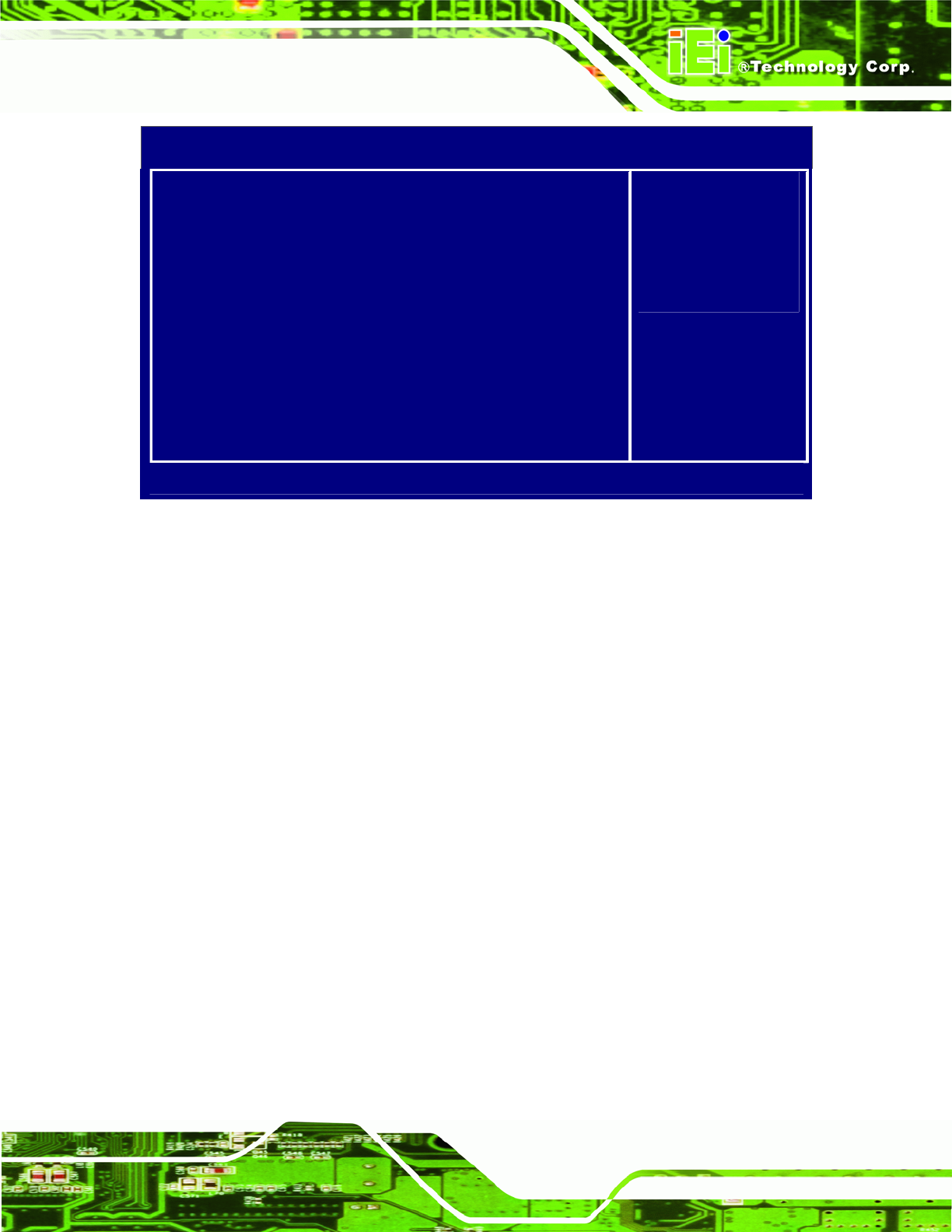
Phoenix - AwardBIOS CMOS Setup Utility
Power Management Setup
AC Power mode [ATX]
HDD Power Down [Disabled]
Soft-Off by PWR-BTTN [Instant-Off]
> RTC Alarm Item [Press Enter]
Item Help
Menu Level >
B
IOS emulated AC
Power mode.
AT-No S1~S5 support.
↑ ↓:Move Enter:Select +/-/PU/PD:Value F10:Save Esc:Exit F1:General Help
F5=Previous Values F6:Fail-Safe Defaults F7 Optimized Defaults
BIOS Menu 10: Power Management Setup
AC Power mode [ATX]
Use the AC Power mode option to specify whether an AT or ATX power supply is
connected to the system.
ATX
(Default) An ATX power supply is used.
AT
An AT power supply is used.
HDD Power Do wn [Disabled]
Use the HDD Power Down option to specify how long the computer must wait for no
activity before the HDD powers down. If this option is disabled, the HDD does not power
down. The following settings can be made.
Disabled (Default)
1 Sec
5 Sec
10 Sec
15 Sec
30 Sec