
User Manual


Table Of Contents
- 1 Introduction
- 2 Unpacking
- 3 Connectors
- 3.1 Peripheral Interface Connectors
- 3.2 Internal Peripheral Connectors
- 3.2.1 ATX Power Enable Connector
- 3.2.2 Audio Connector (10-pin)
- 3.2.3 Backlight Inverter Connector
- 3.2.4 Battery Connector
- 3.2.5 CompactFlash® Socket
- 3.2.6 Digital Input/Output (DIO) Connector
- 3.2.7 Fan Connector (+5V)
- 3.2.8 Floppy Disk Connector
- 3.2.9 Front Panel Connector (8-pin)
- 3.2.10 IDE Connector (40-pin)
- 3.2.11 Infrared Interface Connector (5-pin)
- 3.2.12 Keyboard/Mouse Connector
- 3.2.13 Parallel Port Connector
- 3.2.14 Power Connector
- 3.2.15 SATA Drive Connectors (Optional)
- 3.2.16 Serial Port Connector (RS-232/422/485)
- 3.2.17 TTL Connector
- 3.2.18 Internal USB Connectors
- 3.2.19 -VCC Power Connector
- 3.3 External Peripheral Interface Connectors
- 4 Installation
- 5 BIOS Screens
- A BIOS Menu Options
- B One Key Recovery
- C Terminology
- D Watchdog Timer
- E Hazardous Materials Disclosure
IOWA-LX-600 Half-size CPU Card
Page 126
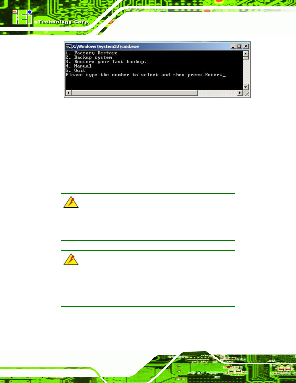
Figure B-26: Recovery Tool Main Menu
The recovery tool has several functions including:
1. Factory Restore: Restore the factory default image (iei.GHO ) created in
Section
787B.2.5.
2. Backup system: Create a system backup image (iei_user.GHO) which will
be saved in the hidden p artition.
3. Restore your last backup: Restore the last syste m backup image
4. Manual: Enter the Symantec Ghost window to configure manually.
5. Quit: Exit the recovery tool and restart the system.
WARNING:
Please do not turn off the system power during the process of system
recovery or backup.
WARNING:
All data in the system will be deleted during the system recovery.
Please backup the system files before restoring the system (either
Factory Restore or Restore Backup ).