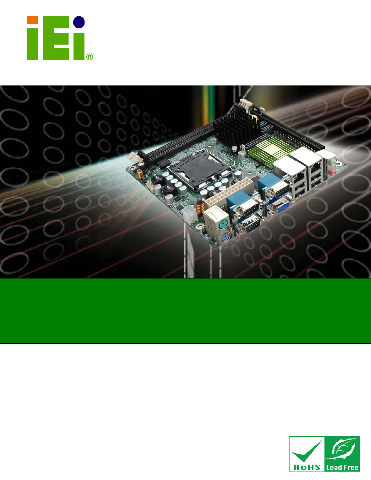
KINO-G410 Min i-ITX Mo th e rb o a rd IEI Te c h n o lo g y Co rp . MODEL: KINO-G410 Min i-ITX Mo th e rb o a rd fo r In te l® Co re ™2 Du o /Qu a d /Extre m e CP U, 800/1066/1333 MHz FS B, DDR3, VGA, LAN, S ATA 3Gb /s , P CIe x16, US B, HD Au d io , Ro HS Co m p lia n t Us e r Ma n u a l Page i Re v. 2.
KINO-G410 Min i-ITX Mo th e rb o a rd Re vis io n Date Version Changes 6 March, 2012 2.00 Update the version number 20 January, 2012 1.03 Update the BIOS section 17 August, 2011 1.02 Modified Figure 4-9 4 March, 2011 1.01 Modified VGA to LVDS connector pinouts (Table 3-16) 13 September, 2010 1.
KINO-G410 Min i-ITX Mo th e rb o a rd Co p yrig h t COP YRIGHT NOTICE The information in this document is subject to change without prior notice in order to improve reliability, design and function and does not represent a commitment on the part of the manufacturer. In no event will the manufacturer be liable for direct, indirect, special, incidental, or consequential damages arising out of the use or inability to use the product or documentation, even if advised of the possibility of such damages.
KINO-G410 Min i-ITX Mo th e rb o a rd Ta b le o f Co n te n ts 1 INTRODUCTION.......................................................................................................... 1 1.1 INTRODUCTION........................................................................................................... 2 1.2 BENEFITS ................................................................................................................... 2 1.3 FEATURES .......................................................
KINO-G410 Min i-ITX Mo th e rb o a rd 3.2.11 RS-232/422/485 Serial Port Connector ......................................................... 25 3.2.12 SATA Drive Connectors ................................................................................. 26 3.2.13 SMBus Connector .......................................................................................... 26 3.2.14 SPI Flash Connector ...................................................................................... 27 3.2.
KINO-G410 Min i-ITX Mo th e rb o a rd 4.7 SOFTWARE INSTALLATION ........................................................................................ 55 5 BIOS .............................................................................................................................. 56 5.1 INTRODUCTION......................................................................................................... 57 5.1.1 Starting Setup .........................................................................
KINO-G410 Min i-ITX Mo th e rb o a rd C.1.2 Supported Operating System ......................................................................... 106 C.2 SETUP PROCEDURE FOR WINDOWS ........................................................................ 107 C.2.1 Hardware and BIOS Setup ............................................................................ 107 C.2.2 Create Partitions ........................................................................................... 108 C.2.
KINO-G410 Min i-ITX Mo th e rb o a rd Lis t o f Fig u re s Figure 1-1: KINO-G410 ...................................................................................................................2 Figure 1-2: Connectors ..................................................................................................................3 Figure 1-3: Dimensions (mm) ........................................................................................................4 Figure 1-4: Data Flow Diagram ..........
KINO-G410 Min i-ITX Mo th e rb o a rd Figure 4-5: Cooling Kits ...............................................................................................................41 Figure 4-6: Securing the Heat sink to the KINO-G410 ..............................................................42 Figure 4-7: DIMM Installation .......................................................................................................43 Figure 4-8: Clear BIOS Jumper Location ...........................................
KINO-G410 Min i-ITX Mo th e rb o a rd Figure C-22: Partitions for Linux...............................................................................................120 Figure C-23: System Configuration for Linux ..........................................................................121 Figure C-24: Access menu.lst in Linux (Text Mode) ...............................................................121 Figure C-25: Recovery Tool Menu .......................................................................
KINO-G410 Min i-ITX Mo th e rb o a rd Lis t o f Ta b le s Table 1-1: Technical Specifications ..............................................................................................7 Table 2-1: Packing List .................................................................................................................10 Table 2-2: Optional Items .............................................................................................................12 Table 3–1: Internal Peripheral Connectors .
KINO-G410 Min i-ITX Mo th e rb o a rd BIOS Me n u s BIOS Menu 1: Main .......................................................................................................................59 BIOS Menu 2: Advanced ..............................................................................................................60 BIOS Menu 3: CPU Configuration ...............................................................................................61 BIOS Menu 4: IDE Configuration ........................
KINO-G410 Min i-ITX Mo th e rb o a rd Ch a p te r 1 1 In tro d u c tio n Page 1
KINO-G410 Min i-ITX Mo th e rb o a rd 1.1 In tro d u c tio n Figure 1-1: KINO-G410 The KINO-G410 is a Mini-ITX motherboard with an 800/1066/1333 MHz front side bus. The LGA775 socket accepts Intel® Core™2 Duo/Quad/Extreme processors and the card supports two DDR3 DIMMs up to 2.0 GB each (4.0 GB total). The KINO-G410 includes VGA output and an optional 24-bit LVDS output. One PCIe x16 expansion card may be added.
KINO-G410 Min i-ITX Mo th e rb o a rd RoHS compliant LGA775 CPU socket Supports two DDR3 DIMMs Two Gigabit Ethernet connectors Four SATA connectors Eight USB ports Six serial ports Support 24-bit LVDS by the optional VGA to LVDS converter module 1.4 Co n n e c to rs The connectors on the KINO-G410 are shown in the figure below.
KINO-G410 Min i-ITX Mo th e rb o a rd 1.5 Dim e n s io n s The main dimensions of the KINO-G410 are shown in the diagram below.
KINO-G410 Min i-ITX Mo th e rb o a rd 1.6 Da ta Flo w Figure 1-4 shows the data flow between the system chipset, the CPU and other components installed on the motherboard.
KINO-G410 Min i-ITX Mo th e rb o a rd 1.7 Te c h n ic a l Sp e c ific a tio n s KINO-G410 technical specifications are shown below. S p e c ific a tio n s KINO-G410 Fo rm Fa c to r Mini-ITX CP U S u p p o rte d Socket LGA775 Intel® Core™2 Duo/Quad/Extreme or Celeron® processor Fro n t S id e Bu s (FS B) 800/1066/1333 MHz No rth b rid g e Ch ip s e t Intel® G41 Me m o ry Two 240-pin 800/1066 MHz dual-channel DDR3 SDRAM DIMMs (system max.
KINO-G410 Min i-ITX Mo th e rb o a rd S e ria l P o rts Five RS-232 COM connectors One RS-232/422/485 COM connector US B 2.0/1.1 p o rts Four internal via pin header Four external USB ports P a ra lle l P o rt One parallel port via 26-pin header S e ria l ATA Four independent SATA channels with 3.0 Gb/s data transfer rates En viro n m e n ta l a n d P owe r S p e c ific a tio n s P owe r S u p p ly ATX supported P owe r Co n s u m p tio n 5 V @ 6.41 A Vcore_12 V @ 2.52 A 3.3 V @ 0.27 A (2.
KINO-G410 Min i-ITX Mo th e rb o a rd Ch a p te r 2 2 P a c kin g Lis t Page 8
KINO-G410 Min i-ITX Mo th e rb o a rd 2.1 An ti-s ta tic P re c a u tio n s WARNING! Static electricity can destroy certain electronics. Make sure to follow the ESD precautions to prevent damage to the product, and injury to the user. Make sure to adhere to the following guidelines: Wear an anti-static wristband: Wearing an anti-static wristband can prevent electrostatic discharge. Self-grounding: Touch a grounded conductor every few minutes to discharge any excess static buildup.
KINO-G410 Min i-ITX Mo th e rb o a rd 2.3 P a c kin g Lis t NOTE: If any of the components listed in the checklist below are missing, do not proceed with the installation. Contact the IEI reseller or vendor the KINO-G410 was purchased from or contact an IEI sales representative directly by sending an email to sales@iei.com.tw. The KINO-G410 is shipped with the following components: Qu a n tity Ite m a n d P a rt Nu m b e r 1 KINO-G410 SBC 2 SATA cable (P/N: 32000-062800-RS) 1 Mini jumper pack (2.
KINO-G410 Min i-ITX Mo th e rb o a rd 2.
KINO-G410 Min i-ITX Mo th e rb o a rd Ite m a n d P a rt Nu m b e r SATA power cable (P/N: 32100-088600-RS 32102-000100-100-RS 32102-000100-200-RS) VGA to LVDS (24-bit) converter module (P/N: VGA-LVDS-R10) Table 2-2: Optional Items P a g e 12 Im a g e
KINO-G410 Min i-ITX Mo th e rb o a rd Ch a p te r 3 3 Co n n e c to rs P a g e 13
KINO-G410 Min i-ITX Mo th e rb o a rd 3.1 P e rip h e ra l In te rfa c e Co n n e c to rs This chapter details all the jumpers and connectors. 3.1.1 La yo u t The figure below shows all the connectors and jumpers.
KINO-G410 Min i-ITX Mo th e rb o a rd 3.1.2 P e rip h e ra l In te rfa c e Co n n e c to rs The table below lists all the connectors on the board.
KINO-G410 Min i-ITX Mo th e rb o a rd Co n n e c to r Typ e La b e l Audio connector Audio jack AUDIO_CV1 Keyboard/Mouse connector PS/2 KBMS1 LAN connector RJ-45 LAN1, LAN2 Serial port connector DB-9 COM1, COM2, COM3 USB connector USB port USB01, USB23 VGA connector 15-pin Female VGA1 Table 3–2: External Peripheral Connectors 3.2 In te rn a l P e rip h e ra l Co n n e c to rs The section describes all of the connectors on the KINO-G410. 3.2.
KINO-G410 Min i-ITX Mo th e rb o a rd Pin Description 1 Battery+ (+3V) 2 Ground Table 3-3: Battery Connector Pinouts 3.2.2 CP U Fa n Co n n e c to r CN La b e l: CP U_FAN1 CN Typ e : 4-pin wafer CN Lo c a tio n : See Figure 3-3 CN P in o u ts : See Table 3-4 The fan connector attaches to a CPU cooling fan.
KINO-G410 Min i-ITX Mo th e rb o a rd 3.2.3 S ys te m Fa n Co n n e c to r CN La b e l: S YS _FAN1 CN Typ e : 3-pin wafer CN Lo c a tio n : See Figure 3-4 CN P in o u ts : See Table 3-5 The fan connector attaches to a system cooling fan. Figure 3-4: CPU Fan Connector Location Pin Description 1 Fan In 2 VCC_FAN 3 GND Table 3-5: CPU Fan Connector Pinouts 3.2.
KINO-G410 Min i-ITX Mo th e rb o a rd Figure 3-5: CPU Power Input Connector Location Pin Description 1 GND 2 GND 3 +12 V 4 +12 V Table 3-6: CPU Power Input Connector Pinouts 3.2.5 Dig ita l I/O Co n n e c to r CN La b e l: DIO1 CN Typ e : 10-pin header CN Lo c a tio n : See Figure 3-6 CN P in o u ts : See Table 3-7 The digital I/O connector provides programmable input and output for external devices. The digital I/O provides 4-bit output and 4-bit input.
KINO-G410 Min i-ITX Mo th e rb o a rd Pin Description Pin Description 1 GND 2 VCC5S 3 Output 3 4 Output 2 5 Output 1 6 Output 0 7 Input 3 8 Input 2 9 Input 1 10 Input 0 Table 3-7: Digital I/O Connector Pinouts 3.2.6 Fro n t P a n e l Co n n e c to r CN La b e l: F_P ANEL1 CN Typ e : 14-pin header CN Lo c a tio n : See Figure 3-7 CN P in o u ts : See Table 3-8 The front panel connector connects to the indicator LEDs and buttons on the computer's front panel.
KINO-G410 Min i-ITX Mo th e rb o a rd FUNCTION PIN DESCRIPTION FUNCTION PIN DESCRIPTION Power LED 1 LED+ Buzzer 2 BEEP_PWR 3 NC 4 NC 5 LED- 6 NC Power 7 BUTTON1 8 PC_BEEP Button 9 BUTTON2 -- 10 NC HDD LED 11 HDD LED+ Reset 12 RESET 13 HDD LED- 14 GND Table 3-8: Front Panel Connector Pinouts 3.2.7 Me m o ry S lo t CN La b e l: DIMM1, DIMM2 CN Typ e : DIMM slot CN Lo c a tio n : See Figure 3-8 The DIMM slots are for DIMM memory modules.
KINO-G410 Min i-ITX Mo th e rb o a rd CN Lo c a tio n : See Figure 3-9 CN P in o u ts : See Table 3-9 The parallel port connector connects to a parallel port connector interface or some other parallel port device such as a printer.
KINO-G410 Min i-ITX Mo th e rb o a rd 3.2.9 P o we r Co n n e c to r CN La b e l: ATX1 CN Typ e : 24-pin connector CN Lo c a tio n : See Figure 3-10 CN P in o u ts : See Table 3-10 The power connector connects to an ATX power supply. Figure 3-10: Power Connector Location Pin Description Pin Description 1 3.3V 13 3.3V 2 3.
KINO-G410 Min i-ITX Mo th e rb o a rd 3.2.10 RS -232 S e ria l P o rt Co n n e c to r CN La b e l: COM4, COM5 CN Typ e : 10-pin header CN Lo c a tio n : See Figure 3-11 CN P in o u ts : See Table 3-11 This connector provides RS-232 communications.
KINO-G410 Min i-ITX Mo th e rb o a rd 3.2.11 RS -232/422/485 S e ria l P o rt Co n n e c to r CN La b e l: COM6 CN Typ e : 14-pin header CN Lo c a tio n : See Figure 3-12 CN P in o u ts : See Table 3-12 This connector provides RS-232, RS-422 or RS-485 communications.
KINO-G410 Min i-ITX Mo th e rb o a rd 3.2.12 S ATA Drive Co n n e c to rs CN La b e l: S ATA1, S ATA2, S ATA3, S ATA4 CN Typ e : 7-pin SATA drive connectors CN Lo c a tio n : See Figure 3-13 The SATA drive connectors can be connected to SATA 3Gb/s drives. Figure 3-13: SATA Drive Connector Location 3.2.
KINO-G410 Min i-ITX Mo th e rb o a rd Figure 3-14: SMBus Connector Location Pin Description 1 GND 2 SDAT 3 SCLK 4 +5V Table 3-13: SMBus Connector Pinouts 3.2.14 S P I Fla s h Co n n e c to r CN La b e l: J S P I1 CN Typ e : 8-pin header CN Lo c a tio n : See Figure 3-15 CN P in o u ts : See Table 3-14 The 8-pin SPI Flash connector is used to flash the BIOS.
KINO-G410 Min i-ITX Mo th e rb o a rd Pin Description Pin Description 1 +3.3V 2 GND 3 CS# 4 CLOCK 5 SO 6 SI 7 NC 8 NC Table 3-14: SPI Flash Connector 3.2.15 US B Co n n e c to rs CN La b e l: US B45, US B67 CN Typ e : 8-pin header CN Lo c a tio n : See Figure 3-16 CN P in o u ts : See Table 3-15 The USB connectors connect to USB devices. Each pin header provides two USB ports.
KINO-G410 Min i-ITX Mo th e rb o a rd 3.2.16 VGA to LVDS Co n n e c to r CN La b e l: J P4 CN Typ e : 20-pin header CN Lo c a tio n : See Figure 3-17 CN P in o u ts : See Table 3-16 This connector connects to the optional VGA to LVDS converter module and provides the 24-bit LVDS interface. Figure 3-17: VGA to LVDS Connector Location Pin Description Pin Description 1 GND 2 +5V 3 H-SYNCBUF-OUT_R 4 NC 5 V-SYNCBUF-OUT_R 6 +5V 7 GND 8 GND 9 CH1BUF-OUT_RED 10 +3.
KINO-G410 Min i-ITX Mo th e rb o a rd 3.3 Exte rn a l P e rip h e ra l In te rfa c e Co n n e c to r P a n e l The figure below shows the external peripheral interface connector (EPIC) panel. The EPIC panel consists of the following: Figure 3-18: External Peripheral Interface Connector 3.3.1 Au d io Co n n e c to r CN La b e l: AUDIO_CV1 CN Typ e : Audio jacks CN Lo c a tio n : See Figure 3-18 The audio jacks connect to external audio devices.
KINO-G410 Min i-ITX Mo th e rb o a rd 3.3.2 Ke yb o a rd /Mo u s e Co n n e c to r CN La b e l: KBMS 1 CN Typ e : PS/2 CN Lo c a tio n : See Figure 3-18 CN P in o u ts : See Table 3-17, Figure 3-20 The keyboard and mouse connector is a standard PS/2 connector. Figure 3-20: PS/2 Pinout and Configuration Pin Description 1 KB DATA 2 MS DATA 3 GND 4 VCC (+5V) 5 KB CLOCK 6 MS CLOCK Table 3-17: Keyboard Connector Pinouts 3.3.
KINO-G410 Min i-ITX Mo th e rb o a rd Pin Description Pin Description 1 MDIA3- 5 MDIA1+ 2 MDIA3+ 6 MDIA2+- 3 MDIA2- 7 MDIA0- 4 MDIA1- 8 MDIA0+ Table 3-18: LAN Pinouts 3.3.4 S e ria l P o rt Co n n e c to rs (COM1, COM2 a n d COM3) CN La b e l: COM1, COM2, COM3 CN Typ e : DB-9 connectors CN Lo c a tio n : See Figure 3-18 CN P in o u ts : See Table 3-19 and Figure 3-21 The serial port connects to a RS-232 serial communications device.
KINO-G410 Min i-ITX Mo th e rb o a rd 3.3.5 US B Co n n e c to r CN La b e l: US B01, US B23 CN Typ e : USB port CN Lo c a tio n : See Figure 3-18 CN P in o u ts : See Table 3-20 The USB connector can be connected to a USB device. Pin Description Pin Description 1 +5 V 2 +5 V 3 DATA- 4 DATA- 5 DATA+ 6 DATA+ 7 GND 8 GND Table 3-20: USB Port Pinouts 3.3.
KINO-G410 Min i-ITX Mo th e rb o a rd Pin Description Pin Description 1 RED 2 GREEN 3 BLUE 4 NC 5 GND 6 GND 7 GND 8 GND 9 VCC / NC 10 GND 11 NC 12 DDC DAT 13 HSYNC 14 VSYNC 15 DDCCLK Table 3-21: VGA Connector Pinouts P a g e 34
KINO-G410 Min i-ITX Mo th e rb o a rd Ch a p te r 4 4 In s ta lla tio n P a g e 35
KINO-G410 Min i-ITX Mo th e rb o a rd 4.1 An ti-s ta tic P re c a u tio n s WARNING: Failure to take ESD precautions during the installation of the KINO-G410 may result in permanent damage to the KINO-G410 and severe injury to the user. Electrostatic discharge (ESD) can cause serious damage to electronic components, including the KINO-G410. Dry climates are especially susceptible to ESD.
KINO-G410 Min i-ITX Mo th e rb o a rd WARNING: The installation instructions described in this manual should be carefully followed in order to prevent damage to the components and injury to the user. Before and during the installation please DO the following: Read the user manual: o The user manual provides a complete description of the KINO-G410 installation instructions and configuration options. Wear an electrostatic discharge cuff (ESD): o Electronic components are easily damaged by ESD.
KINO-G410 Min i-ITX Mo th e rb o a rd 4.3 Ba s ic In s ta lla tio n This section outlines the parts that must be installed for the system to function correctly. 4.3.1 CP U In s ta lla tio n NOTE: To enable Hyper-Threading, the CPU and chipset must both support it. WARNING: CPUs are expensive and sensitive components. When installing the CPU please be careful not to damage it in anyway. Make sure the CPU is installed properly and ensure the correct cooling kit is properly installed.
KINO-G410 Min i-ITX Mo th e rb o a rd WARNING: DO NOT touch the pins at the bottom of the CPU. When handling the CPU, only hold it on the sides. S te p 1: Remove the protective cover. The black protective cover can be removed by pulling up on the tab labeled "Remove". See Figure 4-2. Figure 4-2: Remove Protective Cover S te p 2: Open the socket. Disengage the load lever by pressing the lever down and slightly outward to clear the retention tab. Fully open the lever, then open the load plate.
KINO-G410 Min i-ITX Mo th e rb o a rd S te p 3: Inspect the CPU socket. Make sure there are no bent pins and make sure the socket contacts are free of foreign material. If any debris is found, remove it with compressed air. S te p 4: Orientate the CPU properly. The contact array should be facing the CPU socket. S te p 5: Correctly position the CPU. Match the Pin 1 mark with the cut edge on the CPU socket. S te p 6: Align the CPU pins. Locate pin 1 and the two orientation notches on the CPU.
KINO-G410 Min i-ITX Mo th e rb o a rd 4.3.2 Co o lin g Kit In s ta lla tio n WARNING: DO NOT use the original Intel® heat sink and fan. A proprietary one is recommended. Figure 4-5: Cooling Kits The cooling kit can be bought from IEI. The cooling kit has a heatsink and fan. WARNING: Do not wipe off (accidentally or otherwise) the pre-sprayed layer of thermal paste on the bottom of the heat sink. The thermal paste between the CPU and the heat sink is important for optimum heat dissipation.
KINO-G410 Min i-ITX Mo th e rb o a rd S te p 3: Mount the cooling kit. Gently place the cooling kit on top of the CPU. Make sure the four threaded screws on the corners of the cooling kit properly pass through the predrilled holes on the bottom of the PCB. S te p 4: Secure the cooling kit. From the solder side of the PCB, align the support bracket to the screw threads on heat sink that were inserted through the PCB holes.
KINO-G410 Min i-ITX Mo th e rb o a rd 4.3.3 DIMM In s ta lla tio n To install a DIMM, please follow the steps below and refer to Figure 4-7. Figure 4-7: DIMM Installation S te p 1: Open the DIMM socket handles. Open the two handles outwards as far as they can. See Figure 4-7. S te p 2: Align the DIMM with the socket. Align the DIMM so the notch on the memory lines up with the notch on the memory socket. See Figure 4-7. S te p 3: Insert the DIMM.
KINO-G410 Min i-ITX Mo th e rb o a rd 4.4 J u m p e r S e ttin g s NOTE: A jumper is a metal bridge used to close an electrical circuit. It consists of two or three metal pins and a small metal clip (often protected by a plastic cover) that slides over the pins to connect them. To CLOSE/SHORT a jumper means connecting the pins of the jumper with the plastic clip and to OPEN a jumper means removing the plastic clip from a jumper. The KINO-G410 includes one jumper shown in Table 4-1.
KINO-G410 Min i-ITX Mo th e rb o a rd Pin Description Short 1-2 Normal (Default) Short 2-3 Clear BIOS Table 4-2: Clear BIOS Jumper Settings Figure 4-8: Clear BIOS Jumper Location 4.4.
KINO-G410 Min i-ITX Mo th e rb o a rd Figure 4-9: COM 6 Function Select Jumper Location 4.5 In te rn a l P e rip h e ra l De vic e Co n n e c tio n s This section outlines the installation of peripheral devices to the onboard connectors. 4.5.1 S ATA Drive Co n n e c tio n The KINO-G410 is shipped with two SATA drive cables and one SATA drive power cable. To connect the SATA drives to the connectors, please follow the steps below. S te p 1: Locate the connectors.
KINO-G410 Min i-ITX Mo th e rb o a rd Figure 4-10: SATA Drive Cable Connection S te p 3: Connect the cable to the SATA disk. Connect the connector on the other end of the cable to the connector at the back of the SATA drive. See Figure 4-11. S te p 4: Connect the SATA power cable. Connect the SATA power connector to the back of the SATA drive. See Figure 4-11.
KINO-G410 Min i-ITX Mo th e rb o a rd Figure 4-11: SATA Power Drive Connection 4.5.2 US B Ca b le (Du a l P o rt) with S lo t Bra c ke t The KINO-G410 is shipped with a dual port USB 2.0 cable. To connect the USB cable connector, please follow the steps below. S te p 1: Locate the connectors. The locations of the USB connectors are shown in Chapter 3. WARNING: If the USB pins are not properly aligned, the USB device can burn out. S te p 2: Align the connectors. The cable has two connectors.
KINO-G410 Min i-ITX Mo th e rb o a rd S te p 3: Insert the cable connectors. Once the cable connectors are properly aligned with the USB connectors on the KINO-G410, connect the cable connectors to the on-board connectors. See Figure 4-12. Figure 4-12: Dual USB Cable Connection S te p 4: Attach the bracket to the chassis. The USB 2.0 connectors are attached to a bracket. To secure the bracket to the chassis please refer to the installation instructions that came with the chassis.S te p 0: 4.
KINO-G410 Min i-ITX Mo th e rb o a rd Plug the audio plugs into the audio jacks. Plug the audio plugs into the audio S te p 2: jacks. If the plugs on your speakers are different, an adapter will need to be used to plug them into the audio jacks. Line Out port (Lime): Connects to a headphone or a speaker. Microphone (Pink): Connects to a microphone. Figure 4-13: Audio Connector S te p 3: Check audio clarity.
KINO-G410 Min i-ITX Mo th e rb o a rd Figure 4-14: PS/2 Keyboard/Mouse Connector 4.6.3 LAN Co n n e c tio n There are two external RJ-45 LAN connectors. The RJ-45 connectors enable connection to an external network. To connect a LAN cable with an RJ-45 connector, please follow the instructions below. S te p 1: Locate the RJ-45 connectors. The locations of the USB connectors are shown in Chapter 4. S te p 2: Align the connectors.
KINO-G410 Min i-ITX Mo th e rb o a rd Figure 4-15: LAN Connection S te p 3: Insert the LAN cable RJ-45 connector. Once aligned, gently insert the LAN cable RJ-45 connector into the on-board RJ-45 connector. S te p 0: 4.6.4 S e ria l De vic e Co n n e c tio n The KINO-G410 has three male DB-9 connectors on the external peripheral interface panel for a serial device. Follow the steps below to connect a serial device to the KINO-G410. S te p 1: Locate the DB-9 connector.
KINO-G410 Min i-ITX Mo th e rb o a rd Figure 4-16: Serial Device Connector S te p 3: Secure the connector. Secure the serial device connector to the external interface by tightening the two retention screws on either side of the connector. S te p 0: 4.6.5 US B De vic e Co n n e c tio n The external USB Series "A" receptacle connectors provide easier and quicker access to external USB devices. Follow the steps below to connect USB devices to the KINO-G410.
KINO-G410 Min i-ITX Mo th e rb o a rd Figure 4-17: USB Connector 4.6.6 VGA Mo n ito r Co n n e c tio n The KINO-G410 has a single female DB-15 connector on the external peripheral interface panel. The DB-15 connector is connected to a CRT or VGA monitor. To connect a monitor to the KINO-G410, please follow the instructions below. S te p 1: Locate the female DB-15 connector. The location of the female DB-15 connector is shown in Chapter 3. S te p 2: Align the VGA connector.
KINO-G410 Min i-ITX Mo th e rb o a rd Figure 4-18: VGA Connector S te p 4: Secure the connector. Secure the DB-15 VGA connector from the VGA monitor to the external interface by tightening the two retention screws on either side of the connector. S te p 0: 4.7 S o ftwa re In s ta lla tio n All the drivers for the KINO-G410 are on the CD that came with the system. To install the drivers, please follow the steps below. S te p 1: Insert the CD into a CD drive connected to the system.
KINO-G410 Min i-ITX Mo th e rb o a rd Ch a p te r 5 5 BIOS P a g e 56
KINO-G410 Min i-ITX Mo th e rb o a rd 5.1 In tro d u c tio n The BIOS is programmed onto the BIOS chip. The BIOS setup program allows changes to certain system settings. This chapter outlines the options that can be changed. 5.1.1 Sta rtin g S e tu p The AMI BIOS is activated when the computer is turned on. The setup program can be activated in one of two ways. 1. Press the DELETE key as soon as the system is turned on or 2.
KINO-G410 Min i-ITX Mo th e rb o a rd Ke y Fu n c tio n F2/F3 key Change color from total 3 colors. F2 to select color forward F10 Save all the CMOS changes, only for Main Menu Table 5-1: BIOS Navigation Keys 5.1.3 Ge ttin g He lp When F1 is pressed a small help window describing the appropriate keys to use and the possible selections for the highlighted item appears. To exit the Help Window press ESC or the F1 key again. 5.1.
KINO-G410 Min i-ITX Mo th e rb o a rd 5.2 Ma in The Main BIOS menu (BIOS Menu 1) appears when the BIOS Setup program is entered. The Main menu gives an overview of the basic system information. Main Advanced PCIPnP BIOS SETUP UTILITY Boot Security Chipset System Overview AMIBIOS Version :08.00.15 Build Date :08/05/10 ID: :SA16MR13 Processor Intel(R) Pentium(R) Dual CPU E2160 @ 1.
KINO-G410 Min i-ITX Mo th e rb o a rd The System Overview field also has two user configurable fields: S ys te m Tim e [xx:xx:xx] Use the System Time option to set the system time. Manually enter the hours, minutes and seconds. S ys te m Da te [xx/xx/xx] Use the System Date option to set the system date. Manually enter the day, month and year. 5.
KINO-G410 Min i-ITX Mo th e rb o a rd 5.3.1 CP U Co n fig u ra tio n Use the CPU Configuration menu (BIOS Menu 3) to view detailed CPU specifications and configure the CPU. BIOS SETUP UTILITY Advanced Configure advanced CPU Settings Module Version:3F.15 Manufacturer :Intel Intel(R) Pentium(R) Dual CPU E2160 @ 1.80GHz Frequency :1.
KINO-G410 Min i-ITX Mo th e rb o a rd BIOS SETUP UTILITY Advanced IDE Configuration ATA/IDE Configuration [Enhanced] Configure SATA as [IDE] > > > > > > Primary IDE Master Primary IDE Slave Secondary IDE Master Secondary IDE Slave Third IDE Master Third IDE Slave : : : : : : [Not [Not [Not [Not [Not [Not Detected] Detected] Detected] Detected] Detected] Detected] Options Disabled Compatible Enhanced ↑ ↓ + F1 F10 ESC Select Screen Select Item Change Option General Hel
KINO-G410 Min i-ITX Mo th e rb o a rd When entering setup, BIOS auto detects the presence of IDE devices. BIOS displays the status of the auto detected IDE devices. The following IDE devices are detected and are shown in the IDE Configuration menu: Primary IDE Master Primary IDE Slave Secondary IDE Master Secondary IDE Slave Third IDE Master Third IDE Slave The IDE Configuration menu (BIOS Menu 4) allows changes to the configurations for the IDE devices installed in the system.
KINO-G410 Min i-ITX Mo th e rb o a rd The “grayed-out” items in the left frame are IDE disk drive parameters automatically detected from the firmware of the selected IDE disk drive. The drive parameters are listed as follows: Device: Lists the device type (e.g. hard disk, CD-ROM etc.) Type: Indicates the type of devices a user can manually select Vendor: Lists the device manufacturer Size: List the storage capacity of the device.
KINO-G410 Min i-ITX Mo th e rb o a rd BIOS does not attempt to search for other types of IDE disk drives on the specified channel. ARMD This option specifies an ATAPI Removable Media Device. These include, but are not limited to: ZIP LS-120 LBA/La rg e Mo d e [Au to ] Use the LBA/Large Mode option to disable or enable BIOS to auto detects LBA (Logical Block Addressing). LBA is a method of addressing data on a disk drive. In LBA mode, the maximum drive capacity is 137 GB.
KINO-G410 Min i-ITX Mo th e rb o a rd P IO Mo d e [Au to ] Use the PIO Mode option to select the IDE PIO (Programmable I/O) mode program timing cycles between the IDE drive and the programmable IDE controller. As the PIO mode increases, the cycle time decreases. Auto DEFAULT BIOS auto detects the PIO mode. Use this value if the IDE disk drive support cannot be determined. 0 PIO mode 0 selected with a maximum transfer rate of 3.3MBps 1 PIO mode 1 selected with a maximum transfer rate of 5.
KINO-G410 Min i-ITX Mo th e rb o a rd Multi Word DMA mode 2 selected with a maximum data MWDMA2 transfer rate of 16.6MBps Ultra DMA mode 0 selected with a maximum data transfer UDMA1 rate of 16.6MBps Ultra DMA mode 1 selected with a maximum data transfer UDMA1 rate of 25MBps Ultra DMA mode 2 selected with a maximum data transfer UDMA2 rate of 33.
KINO-G410 Min i-ITX Mo th e rb o a rd Enabled Allows BIOS to use 32-bit data transfers on supported DEFAULT hard disk drives. 5.3.3 S u p e r IO Co n fig u ra tio n Use the Super IO Configuration menu (BIOS Menu 6) to set or change the configurations for the serial ports.
KINO-G410 Min i-ITX Mo th e rb o a rd Use the Serial Port1 IRQ option to select the interrupt address for serial port 1. IRQ4 DEFAULT IRQ3 Serial port 1 IRQ address is IRQ4 Serial port 1 IRQ address is IRQ3 S e ria l P o rt2 Ad d re s s [2F8] Use the Serial Port2 Address option to select the Serial Port 2 base address.
KINO-G410 Min i-ITX Mo th e rb o a rd S e ria l P o rt4 Ad d re s s [2E8] Use the Serial Port4 Address option to select the Serial Port 4 base address. Disabled No base address is assigned to Serial Port 4 3E8 Serial Port 4 I/O port address is 3E8 2E8 DEFAULT Serial Port 4 I/O port address is 2E8 S e ria l P o rt4 IRQ [IRQ10] Use the Serial Port4 IRQ option to select the interrupt address for serial port 4.
KINO-G410 Min i-ITX Mo th e rb o a rd 328 Serial Port 6 I/O port address is 328 DEFAULT S e ria l P o rt6 IRQ [IRQ10] Use the Serial Port6 IRQ option to select the interrupt address for serial port 6. IRQ10 Serial port 6 IRQ address is IRQ10 DEFAULT IRQ11 Serial port 6 IRQ address is IRQ11 S e le c t RS 232 o r RS 422/RS 485 [RS 232] Use the Select RS232 or RS422/RS485 option to select the Serial Port 2 signaling mode.
KINO-G410 Min i-ITX Mo th e rb o a rd Normal DEFAULT The normal parallel port mode is the standard mode for parallel port operation. Bi-Directional Parallel port outputs are 8-bits long. Inputs are accomplished by reading 4 of the 8 bits on the status register. The ECP parallel port operates in the extended capabilities port (ECP) mode.
KINO-G410 Min i-ITX Mo th e rb o a rd 5.3.4 Ha rd wa re He a lth Co n fig u ra tio n The Hardware Health Configuration menu (BIOS Menu 7) shows the operating temperature, fan speed and system voltages. BIOS SETUP UTILITY Advanced Hardware Health Configuration CPU FAN1 Mode Setting [Auto Fan by RPM] CPU Temp. Limit of Highest [050] CPU Temp. Limit of Second [040] CPU Temp. Limit of Third [030] CPU Temp.
KINO-G410 Min i-ITX Mo th e rb o a rd CP U FAN1 Mo d e S e ttin g [Au to Fa n b y RP M] Use the CPU FAN1 Mode Setting option to configure the CPU Fan.
KINO-G410 Min i-ITX Mo th e rb o a rd Manual Mode The fan spins at the speed set in Manual Mode by by RPM RPM settings Manual Mode The fan spins at the speed set in Manual Mode by by Duty-Cycle Duty-Cycle settings S YS Te m p . Lim it o f Hig h e s t / S e c o n d / Th ird / Lowe s t [n ] Use the + or – key to change the NB Temp. Limit of Highest / Second / Third / Lowest value. Enter a decimal number between 0 and 127.
KINO-G410 Min i-ITX Mo th e rb o a rd o VBAT 5.3.5 P o we r Co n fig u ra tio n The Power Configuration menu (BIOS Menu 8) configures the Advanced Configuration and Power Interface (ACPI) and Power Management (APM) options. BIOS SETUP UTILITY Advanced Select AT/ATX Power [ATX Power] > ACPI Configuration > APM Configuration Default set ATX power Supply status If set AT Power, Power State will Auto set Power On.
KINO-G410 Min i-ITX Mo th e rb o a rd 5.3.5.1 ACP I c o n fig u ra tio n The ACPI Configuration menu (BIOS Menu 9) configures the Advanced Configuration and Power Interface (ACPI). BIOS SETUP UTILITY Advanced ACPI Settings Suspend mode [S1 (POS)] Select the ACPI state used for System Suspend. ↑ ↓ + F1 F10 ESC Select Screen Select Item Change Option General Help Save and Exit Exit v02.61 ©Copyright 1985-2006, American Megatrends, Inc.
KINO-G410 Min i-ITX Mo th e rb o a rd BIOS SETUP UTILITY Advanced APM Configuration Restore on AC Power Loss [Last State] Advanced Resume Event Controls Resume On RTC Alarm If the AT/ATX power been set to AT mode, this item will be changed to “power on” automatically. [Disabled] Please change to This item after set To ATX power mode. ↑ ↓ + F1 F10 ESC Select Screen Select Item Change Option General Help Save and Exit Exit v02.
KINO-G410 Min i-ITX Mo th e rb o a rd RTC Alarm Date (Days) System Time After setting the alarm, the computer turns itself on from a suspend state when the alarm goes off. 5.3.6 Re m o te Ac c e s s Co n fig u ra tio n Use the Remote Access Configuration menu (BIOS Menu 11) to configure remote access parameters. The Remote Access Configuration is an AMIBIOS feature and allows a remote host running a terminal program to display and configure the BIOS settings.
KINO-G410 Min i-ITX Mo th e rb o a rd Serial Port Mode Redirection after BIOS POST Terminal Type These configuration options are discussed below. When the Remote Access option is set to Enabled, the following sub-menus appear. Serial port number Base Address, IRQ Serial Port Mode Redirection After BIOS POST Terminal Type S e ria l p o rt n u m b e r [COM1] Use the Serial port number option to select the serial port used for remote access.
KINO-G410 Min i-ITX Mo th e rb o a rd Use the Serial Port Mode option to select baud rate through which the console redirection is made.
KINO-G410 Min i-ITX Mo th e rb o a rd 5.3.7 US B Co n fig u ra tio n Use the USB Configuration menu (BIOS Menu 12) to read USB configuration information and configure the USB settings. Main Advanced BIOS SETUP UTILITY Boot Security PCIPnP Chipset USB Configuration Module Version – 2.24.3-13.4 Exit Options Disabled Enabled USB Devices Enabled: 1 Keyboard USB Functions USB 2.0 Controller Legacy USB Support USB 2.
KINO-G410 Min i-ITX Mo th e rb o a rd Normally if this option is not enabled, any attached USB mouse or USB keyboard does not become available until a USB compatible operating system is fully booted with all USB drivers loaded. When this option is enabled, any attached USB mouse or USB keyboard can control the system even when there is no USB driver loaded onto the system.
KINO-G410 Min i-ITX Mo th e rb o a rd Main Advanced PCIPnP BIOS SETUP UTILITY Boot Security Chipset Advanced PCI/PnP Settings WARNING: Setting wrong values in below sections may cause system to malfunction.
KINO-G410 Min i-ITX Mo th e rb o a rd IRQ9 IRQ10 IRQ 11 IRQ 14 IRQ 15 DMA Ch a n n e l# [Ava ila b le ] Use the DMA Channel# option to assign a specific DMA channel to a particular PCI/PnP device.
KINO-G410 Min i-ITX Mo th e rb o a rd 5.5 Bo o t Use the Boot menu (BIOS Menu 14) to configure system boot options. Main Advanced PCIPnP BIOS SETUP UTILITY Boot Security Chipset Boot Settings > Boot Settings Configuration Exit Configure settings during system boot. ↑ ↓ Enter F1 F10 ESC Select Screen Select Item Go to Sub Screen General Help Save and Exit Exit v02.61 ©Copyright 1985-2006, American Megatrends, Inc. BIOS Menu 14: Boot 5.5.
KINO-G410 Min i-ITX Mo th e rb o a rd Qu ic k Bo o t [En a b le d ] Use the Quick Boot BIOS option to make the computer speed up the boot process. Disabled Enabled No POST procedures are skipped DEFAULT Some POST procedures are skipped to decrease the system boot time Qu ie t Bo o t [En a b le d ] Use the Quiet Boot BIOS option to select the screen display when the system boots.
KINO-G410 Min i-ITX Mo th e rb o a rd automatically when the computer system boots up. This allows the immediate use of the 10-key numeric keypad located on the right side of the keyboard. To confirm this, the Number Lock LED light on the keyboard is lit. Bo o t Fro m LAN S u p p o rt [Dis a b le d ] The Boot From LAN Support option enables the system to be booted from a remote system. Disabled DEFAULT Cannot be booted from a remote system through the LAN.
KINO-G410 Min i-ITX Mo th e rb o a rd this field and enter the password. After the password has been added, Install appears next to Change Supervisor Password. Ch a n g e Us e r P a s s wo rd Use the Change User Password to set or change a user password. The default for this option is Not Installed. If a user password must be installed, select this field and enter the password. After the password has been added, Install appears next to Change User Password.
KINO-G410 Min i-ITX Mo th e rb o a rd 5.7 Ch ips e t Use the Chipset menu (BIOS Menu 17) to access the NorthBridge and SouthBridge configuration menus. WARNING! Setting the wrong values for the Chipset BIOS selections in the Chipset BIOS menu may cause the system to malfunction. Main Advanced PCIPnP BIOS SETUP UTILITY Boot Security Chipset Advanced Chipset Settings WARNING: Setting wrong values in below section may cause system to malfunction.
KINO-G410 Min i-ITX Mo th e rb o a rd BIOS SETUP UTILITY Chipset North Bridge Chipset Configuration Memory Hole [Disabled] Initate Graphic Adapter Internal Graphics Mode Select Boot Display Device Options Disabled 15MB-16MB [PEG/IGD] [Enabled, 32MB] [CRT] ↑ ↓ + F1 F10 ESC Select Screen Select Item Change Option General Help Save and Exit Exit v02.61 ©Copyright 1985-2006, American Megatrends, Inc.
KINO-G410 Min i-ITX Mo th e rb o a rd Disabled Enabled, 32MB Enabled, 64MB 64MB of memory used by internal graphics device Enabled, 128MB 128MB of memory used by internal graphics DEFAULT 32MB of memory used by internal graphics device device Bo o t Dis p la y De vic e [Au to ] The Boot Display Device BIOS option selects the display device the system uses when it boots. The available options are listed below: CRT CRT+LVDS DEFAULT 5.7.
KINO-G410 Min i-ITX Mo th e rb o a rd Auto DEFAULT The on-board audio controller is detected and automatically enabled. The on-board audio controller is disabled. Disabled Sp re a d Sp e c tru m Fu n c tio n [Dis a b le d ] Use the Spread Spectrum Function option to reduce the EMI. Excess EMI is generated when the system clock generator pulses have extreme values. Spreading the pulse spectrum modulates changes in the extreme values from spikes to flat curves, thus reducing the EMI.
KINO-G410 Min i-ITX Mo th e rb o a rd Use the Save Changes and Exit option to save the changes made to the BIOS options and to exit the BIOS configuration setup program. Dis c a rd Ch a n g e s a n d Exit Use the Discard Changes and Exit option to exit the BIOS configuration setup program without saving the changes made to the system. Dis c a rd Ch a n g e s Use the Discard Changes option to discard the changes and remain in the BIOS configuration setup program.
KINO-G410 Min i-ITX Mo th e rb o a rd Ap p e n d ix A A BIOS Op tio n s P a g e 95
KINO-G410 Min i-ITX Mo th e rb o a rd Below is a list of BIOS configuration options in the BIOS chapter. System Overview .................................................................................................................59 System Time [xx:xx:xx] .......................................................................................................60 System Date [xx/xx/xx] ........................................................................................................
KINO-G410 Min i-ITX Mo th e rb o a rd CPU Fan1 Highest Setting [100] .........................................................................................74 CPU Fan1 Second / Third / Fourth / Lowest Setting [n] ...................................................74 SYS FAN1 Mode Setting [Auto Fan by RPM] ....................................................................74 SYS Temp. Limit of Highest / Second / Third / Lowest [n]...............................................
KINO-G410 Min i-ITX Mo th e rb o a rd Audio Controller [Auto] .......................................................................................................92 Spread Spectrum Function [Disabled] ..............................................................................93 Save Changes and Exit .......................................................................................................93 Discard Changes and Exit............................................................
KINO-G410 Min i-ITX Mo th e rb o a rd Ap p e n d ix B B Te rm in o lo g y P a g e 99
KINO-G410 Min i-ITX Mo th e rb o a rd AC ’97 Audio Codec 97 (AC’97) refers to a codec standard developed by Intel® in 1997. ACP I Advanced Configuration and Power Interface (ACPI) is an OS-directed configuration, power management, and thermal management interface. AHCI Advanced Host Controller Interface (AHCI) is a SATA Host controller register-level interface. ATA The Advanced Technology Attachment (ATA) interface connects storage devices including hard disks and CD-ROM drives to a computer.
KINO-G410 Min i-ITX Mo th e rb o a rd DIMM Dual Inline Memory Modules are a type of RAM that offer a 64-bit data bus and have separate electrical contacts on each side of the module. DIO The digital inputs and digital outputs are general control signals that control the on/off circuit of external devices or TTL devices. Data can be read or written to the selected address to enable the DIO functions.
KINO-G410 Min i-ITX Mo th e rb o a rd LVDS Low-voltage differential signaling (LVDS) is a dual-wire, high-speed differential electrical signaling system commonly used to connect LCD displays to a computer. P OS T The Power-on Self Test (POST) is the pre-boot actions the system performs when the system is turned-on. RAM Random Access Memory (RAM) is volatile memory that loses data when power is lost. RAM has very fast data transfer rates compared to other storage like hard drives.
KINO-G410 Min i-ITX Mo th e rb o a rd Ap p e n d ix C C On e Ke y Re c o ve ry P a g e 103
KINO-G410 Min i-ITX Mo th e rb o a rd C.1 On e Ke y Re c o ve ry In tro d u c tio n The IEI one key recovery is an easy-to-use front end for the Norton Ghost system backup and recovery tool. The one key recovery provides quick and easy shortcuts for creating a backup and reverting to that backup or for reverting to the factory default settings. The IEI One Key Recovery tool menu is shown below.
KINO-G410 Min i-ITX Mo th e rb o a rd C.1.1 S ys te m Re q u ire m e n t NOTE: The recovery CD can only be used with IEI products. The software will fail to run and a warning message will appear when used on non-IEI hardware. To create the system backup, the main storage device must be split into two partitions (three partitions for Linux).
KINO-G410 Min i-ITX Mo th e rb o a rd NOTE: Specialized tools are required to change the partition size if the operating system is already installed. C.1.2 S u p p o rte d Op e ra tin g S ys te m The recovery CD is compatible with both Microsoft Windows and Linux operating system (OS). The supported OS versions are listed below. Microsoft Windows o o o o o o Windows Vista Windows 7 Windows CE 5.0 Windows CE 6.
KINO-G410 Min i-ITX Mo th e rb o a rd NOTE: Installing unsupported OS versions may cause the recovery tool to fail. C.2 S e tu p P ro c e d u re fo r Win d o ws Prior to using the recovery tool to backup or restore Windows system, a few setup procedures are required. S te p 1: Hardware and BIOS setup (see Section C.2.1) S te p 2: Create partitions (see Section C.2.2) S te p 3: Install operating system, drivers and system applications (see Section C.2.
KINO-G410 Min i-ITX Mo th e rb o a rd S te p 4: Turn on the system. S te p 5: Press the key as soon as the system is turned on to enter the BIOS. S te p 6: Select the connected optical disk drive as the 1st boot device. (Boot Boot Device Priority 1st Boot Device). S te p 7: Save changes and restart the computer. Continue to the next section for instructions on partitioning the internal storage.Step0: C.2.
KINO-G410 Min i-ITX Mo th e rb o a rd S te p 3: The recovery tool setup menu is shown as below. Figure C-3: Recovery Tool Setup Menu S te p 4: Press <5> then . Figure C-4: Command Mode S te p 5: The command prompt window appears. Type the following commands (marked in red) to create two partitions. One is for the OS installation; the other is for saving recovery files and images which will be an invisible partition.
KINO-G410 Min i-ITX Mo th e rb o a rd system32>format F: /fs:ntfs /q /v:Recovery /y system32>exit Figure C-5: Partition Creation Commands P a g e 110
KINO-G410 Min i-ITX Mo th e rb o a rd NOTE: Use the following commands to check if the partitions were created successfully. S te p 6: Press any key to exit the recovery tool and automatically reboot the system. Please continue to the following procedure: Build-up Recovery Partition.Step0: C.2.3 In s ta ll Op e ra tin g S ys te m , Drive rs a n d Ap p lic a tio n s Install the operating system onto the unlabelled partition.
KINO-G410 Min i-ITX Mo th e rb o a rd C.2.4 Bu ild -u p Re c o ve ry P a rtitio n S te p 1: Put the recover CD in the optical drive. S te p 2: Start the system. S te p 3: Boot the system from recovery CD. When prompted, press any key to boot from the recovery CD. It will take a while to launch the recovery tool. Please be patient! Figure C-6: Launching the Recovery Tool S te p 4: When the recovery tool setup menu appears, press <2> then .
KINO-G410 Min i-ITX Mo th e rb o a rd recovery files in Section C.2.2 is hidden and the recovery tool is saved in this partition. Figure C-8: Build-up Recovery Partition S te p 6: After completing the system configuration, press any key in the following window to reboot the system. Figure C-9: Press any key to continue S te p 7: Eject the recovery CD.
KINO-G410 Min i-ITX Mo th e rb o a rd C.2.5 Cre a te Fa c to ry De fa u lt Im a g e NOTE: Before creating the factory default image, please configure the system to a factory default environment, including driver and application installations. To create a factory default image, please follow the steps below. S te p 1: Turn on the system. When the following screen displays (Figure C-10), press the key to access the recovery tool.
KINO-G410 Min i-ITX Mo th e rb o a rd Figure C-12: About Symantec Ghost Window S te p 4: Use mouse to navigate to the option shown below (Figure C-13). Figure C-13: Symantec Ghost Path S te p 5: Select the local source drive (Drive 1) as shown in Figure C-14. Then click OK.
KINO-G410 Min i-ITX Mo th e rb o a rd Figure C-14: Select a Local Source Drive S te p 6: Select a source partition (Part 1) from basic drive as shown in Figure C-15. Then click OK. Figure C-15: Select a Source Partition from Basic Drive S te p 7: Select 1.2: [Recovery] NTFS drive and enter a file name called iei (Figure C-16). Click Save. The factory default image will then be saved in the selected recovery drive and named IEI.GHO. WARNING: The file name of the factory default image must be iei.GHO.
KINO-G410 Min i-ITX Mo th e rb o a rd Figure C-16: File Name to Copy Image to S te p 8: When the Compress Image screen in Figure C-17 prompts, click High to make the image file smaller.
KINO-G410 Min i-ITX Mo th e rb o a rd S te p 9: The Proceed with partition image creation window appears, click Yes to continue. Figure C-18: Image Creation Confirmation S te p 10: The Symantec Ghost starts to create the factory default image (Figure C-19). Figure C-19: Image Creation Process S te p 11: When the image creation completes, a screen prompts as shown in Figure C-20. Click Continue and close the Ghost window to exit the program.
KINO-G410 Min i-ITX Mo th e rb o a rd S te p 12: The recovery tool main menu window is shown as below. Press any key to reboot the system. Step0: Figure C-21: Press Any Key to Continue C.3 S e tu p P ro c e d u re fo r Lin u x The initial setup procedures for a Linux system are mostly the same with the procedure for Microsoft Windows. Please follow the steps below to setup the recovery tool for Linux OS. S te p 1: Hardware and BIOS setup. Refer to Section C.2.1.
KINO-G410 Min i-ITX Mo th e rb o a rd NOTE: Please reserve enough space for partition 3 for saving recovery images. Figure C-22: Partitions for Linux S te p 3: Create a recovery partition. Insert the recovery CD into the optical disk drive. Follow Step 1 ~ Step 3 described in Section C.2.2. Then type the following commands (marked in red) to create a partition for recovery images.
KINO-G410 Min i-ITX Mo th e rb o a rd Figure C-23: System Configuration for Linux S te p 5: Access the recovery tool main menu by modifying the “menu.lst”. To first access the recovery tool main menu, the menu.lst must be modified. In Linux system, enter Administrator (root). When prompt appears, type: cd /boot/grub vi menu.lst Figure C-24: Access menu.lst in Linux (Text Mode) S te p 6: Modify the menu.lst as shown below.
KINO-G410 Min i-ITX Mo th e rb o a rd S te p 7: The recovery tool menu appears. (Figure C-25) Figure C-25: Recovery Tool Menu S te p 8: Create a factory default image. Follow Step 2 ~ Step 12 described in Section C.2.5 to create a factory default image. C.4 Re c o ve ry To o l Fu n c tio n s After completing the initial setup procedures as described above, users can access the recovery tool by pressing while booting up the system. The main menu of the recovery tool is shown below.
KINO-G410 Min i-ITX Mo th e rb o a rd Figure C-26: Recovery Tool Main Menu The recovery tool has several functions including: 1. Factory Restore: Restore the factory default image (iei.GHO) created in Section C.2.5. 2. Backup system: Create a system backup image (iei_user.GHO) which will be saved in the hidden partition. 3. Restore your last backup: Restore the last system backup image 4. Manual: Enter the Symantec Ghost window to configure manually. 5. Quit: Exit the recovery tool and restart the system.
KINO-G410 Min i-ITX Mo th e rb o a rd C.4.1 Fa c to ry Re s to re To restore the factory default image, please follow the steps below. S te p 1: Type <1> and press in the main menu. S te p 2: The Symantec Ghost window appears and starts to restore the factory default. A factory default image called iei.GHO is created in the hidden Recovery partition. Figure C-27: Restore Factory Default S te p 3: The screen is shown as in Figure C-28 when completed. Press any key to reboot the system.
KINO-G410 Min i-ITX Mo th e rb o a rd C.4.2 Ba c ku p S ys te m To backup the system, please follow the steps below. S te p 1: Type <2> and press in the main menu. S te p 2: The Symantec Ghost window appears and starts to backup the system. A backup image called iei_user.GHO is created in the hidden Recovery partition. Figure C-29: Backup System S te p 3: The screen is shown as in Figure C-30 when system backup is completed. Press any key to reboot the system.
KINO-G410 Min i-ITX Mo th e rb o a rd C.4.3 Re s to re Yo u r La s t Ba c ku p To restore the last system backup, please follow the steps below. S te p 1: Type <3> and press in the main menu. S te p 2: The Symantec Ghost window appears and starts to restore the last backup image (iei_user.GHO). Figure C-31: Restore Backup S te p 3: The screen is shown as in Figure C-32 when backup recovery is completed. Press any key to reboot the system.
KINO-G410 Min i-ITX Mo th e rb o a rd C.4.4 Ma n u a l To restore the last system backup, please follow the steps below. S te p 1: Type <4> and press in the main menu. S te p 2: The Symantec Ghost window appears. Use the Ghost program to backup or recover the system manually. Figure C-33: Symantec Ghost Window S te p 3: When backup or recovery is completed, press any key to reboot the system.
KINO-G410 Min i-ITX Mo th e rb o a rd C.5 Oth e r In fo rm a tio n C.5.1 Us in g AHCI Mo d e o r ALi M5283 / VIA VT6421A Co n tro lle r When the system uses AHCI mode or some specific SATA controllers such as ALi M5283 or VIA VT6421A, the SATA RAID/AHCI driver must be installed before using one key recovery. Please follow the steps below to install the SATA RAID/AHCI driver. S te p 1: Copy the SATA RAID/AHCI driver to a floppy disk and insert the floppy disk into a USB floppy disk drive.
KINO-G410 Min i-ITX Mo th e rb o a rd S te p 5: When the following window appears, press to select “Specify Additional Device”. S te p 6: In the following window, select a SATA controller mode used in the system. Then press . The user can now start using the SATA HDD.
KINO-G410 Min i-ITX Mo th e rb o a rd After pressing , the system will get into the recovery tool setup menu. S te p 7: Continue to follow the setup procedure from Step 4 in Section C.2.2 Create Partitions to finish the whole setup process.Step0: C.5.2 S ys te m Me m o ry Re q u ire m e n t To be able to access the recovery tool by pressing while booting up the system, please make sure to have enough system memory. The minimum memory requirement is listed below.
KINO-G410 Min i-ITX Mo th e rb o a rd Ap p e n d ix D D Wa tc h d o g Tim e r P a g e 131
KINO-G410 Min i-ITX Mo th e rb o a rd NOTE: The following discussion applies to DOS. Contact IEI support or visit the IEI website for drivers for other operating systems. The Watchdog Timer is a hardware-based timer that attempts to restart the system when it stops working. The system may stop working because of external EMI or software bugs. The Watchdog Timer ensures that standalone systems like ATMs will automatically attempt to restart in the case of system problems.
KINO-G410 Min i-ITX Mo th e rb o a rd NOTE: The Watchdog Timer is activated through software. The software application that activates the Watchdog Timer must also deactivate it when closed. If the Watchdog Timer is not deactivated, the system will automatically restart after the Timer has finished its countdown.
KINO-G410 Min i-ITX Mo th e rb o a rd Ap p e n d ix E E Dig ita l I/O In te rfa c e P a g e 134
KINO-G410 Min i-ITX Mo th e rb o a rd E.1 In tro d u c tio n The digital I/O is used for machine control and automation. E.2 DIO Co n n e c to r P in o u ts Located in the Connectors section of this document. E.
KINO-G410 Min i-ITX Mo th e rb o a rd Ap p e n d ix F F Ha za rd o u s Ma te ria ls Dis c lo s u re P a g e 136
KINO-G410 Min i-ITX Mo th e rb o a rd F.1 Ha za rd o u s Ma te ria ls Dis c lo s u re Ta b le fo r IP B P ro d u c ts Ce rtifie d a s Ro HS Co m p lia n t Un d e r 2002/95/EC With o u t Me rc u ry The details provided in this appendix are to ensure that the product is compliant with the Peoples Republic of China (China) RoHS standards. The table below acknowledges the presences of small quantities of certain materials in the product, and is applicable to China RoHS only.
KINO-G410 Min i-ITX Mo th e rb o a rd P a rt Na m e To xic o r Ha za rd o u s S u b s ta n c e s a n d Ele m e n ts Le a d Me rc u ry Ca d m iu m He xa va le n t P o lyb ro m in a te d P o lyb ro m in a te d (P b ) (Hg ) (Cd ) Ch ro m iu m Bip h e n yls Dip h e n yl (CR(VI)) (P BB) Eth e rs (P BDE) Ho u s in g X O O O O X Dis p la y X O O O O X P rin te d Circ u it X O O O O X X O O O O O X O O O O X Fa n As s e m b ly X O O O O X P owe r S u p p ly X
KINO-G410 Min i-ITX Mo th e rb o a rd 此附件旨在确保本产品符合中国 RoHS 标准。以下表格标示此产品中某有毒物质的含量符 合中国 RoHS 标准规定的限量要求。 本产品上会附有”环境友好使用期限”的标签,此期限是估算这些物质”不会有泄漏或突变”的 年限。本 产品可能包含有较短的环境友好使用期限的可替换元件,像是电池或灯管,这些元 件将会单独标示出来。 部件名称 有毒有害物质或元素 铅 汞 镉 六价铬 多溴联苯 多溴二苯 (P b ) (Hg ) (Cd ) (CR(VI)) (P BB) 醚 (P BDE) 壳体 X O O O O X 显示 X O O O O X 印刷电路板 X O O O O X 金属螺帽 X O O O O O 电缆组装 X O O O O X 风扇组装 X O O O O X 电力供应组装 X O O O O X 电池 O O O O O O O: 表示该有毒有害物质在该部件所有物质材料中的含量均在 SJ/