
Instruction Manual

LCD-KIT
Page 44
Pin Description Pin
Description Pin
Description
1 TMDS Data2- 9 TMDS Data1- 17 TMDS Data0-
2 TMDS Data2+ 10 TMDS Data1+ 18 TMDSData0+
3 TMDS Data2/4 Shield 11 TMDS Data1/3 Shield
19 TMDS Data0/5 Shield
4 TMDS Data4- 12 TMDS Data3- 20 TMDS Data5-
5 TMDS Data4+ 13 TMDS Data3+ 21 TMDS Data5+
6 DDC Clock [SCL] 14 +5 V Power 22 TMDS Clock Shield
7 DDC Data [SDA] 15 Ground (for +5 V) 23 TMDS Clock +
8 Analog vertical sync 16 Hot Plug Detect 24 TMDS Clock -
Table 5-3: DVI-D Connector Pinouts
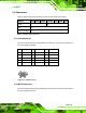
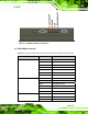
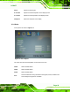
Figure 5-2: DVI-D Connector
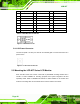
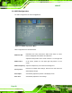
5.4.3 12V Power Connector
Use the rear panel +12V DC (or 9~36V DC on M models) jack to connect the monitor to a
power source.
Figure 5-3: 12V Power Connector
5.5 Mounting the LCD-KIT Series LCD Monitor
Each LCD-KIT series LCD monitor comes with a preinstalled mounting bracket with a
number of holes available for mounting purposes that system integrators will find
especially useful. Refer to Sections
42.4 and 42.5 for further details on the number and
location of mounting holes for each model of the LCD-KIT series LCD monitor.